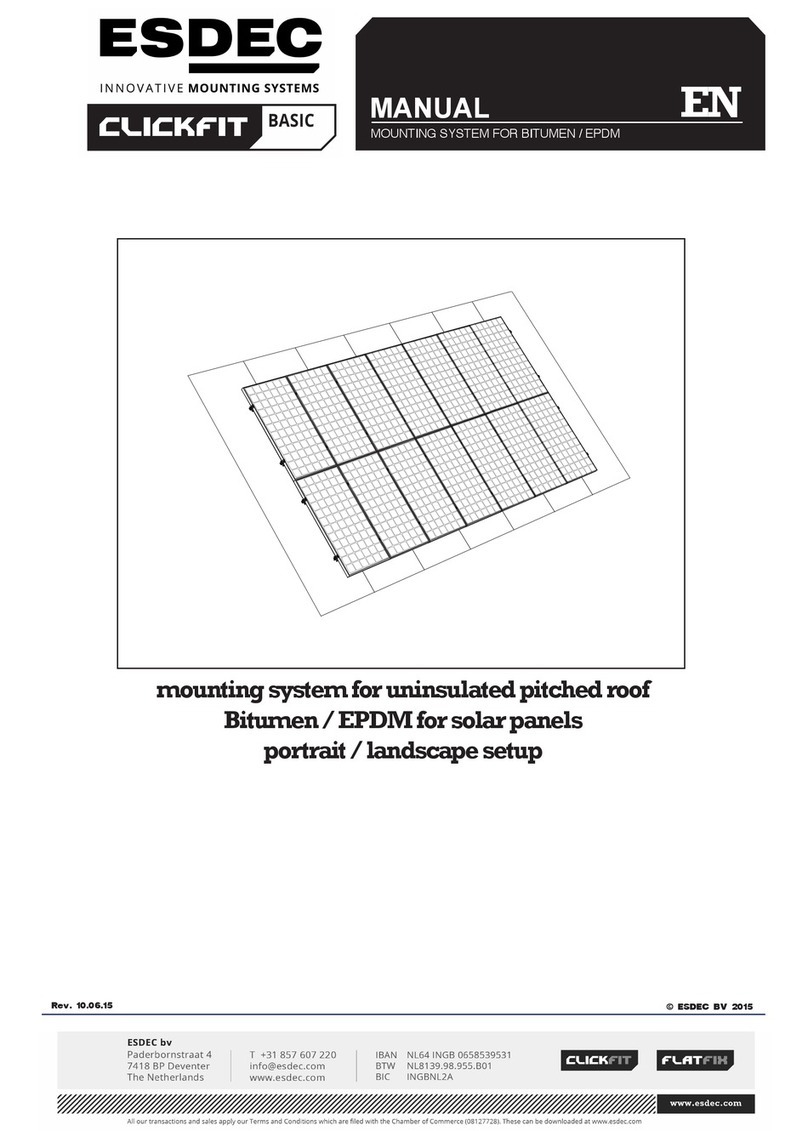
ESDEC FlatFix Fusion User manual

FlatFix Fusion
mounting system for flat roofs
for solar panels in a dual
landscape arrangement
EN
FLATFIX FUSION MOUNTING SYSTEM FOR FLAT ROOFS
MANUAL
©ESDEC BV 2017
Rev. 30.11.17

CONTENT
pag
1. Introduction 1
2. EC declaration of conformity 1
3. General installation conditions 2
4. Product description 4
5. Components overview 4
5.1 Exploded-view 4
5.2 List of parts 5
6. Assembling preparation 6
6.1 Control tools and accessories 6
6.2 Determining position and measuring solar panels 7
6.3 Cleaning the roof 7
7. Installation 8
7.1 Mounting of roof support to base elements 8
7.2 Grounding and mounting of base profile to base elements 9
7.3 Positioning of FlatFix Fusion segments 11
7.4 Mounting of ballast holders 11
7.5 Grounding and mounting of 1st solar panel 13
7.6 Mounting of other solar panels 14
7.7 Mounting of cable clips & cables 15
7.8 Grounding of multiple rows (option) 16
7.9 Grounding of ballast holders (option) 17
7.10 Placement of ballast 18
7.11 Mounting and grounding of stabilizers 19
7.12 Mounting of 2nd row of solar panels 20
7.13 Mounting of wind deflector left/right 21
7.14 Several rows behind one another 22
7.15 Shorten base profile (option) 22
8. Annex 23
THESE INSTALLATION INSTRUCTIONS SHOULD REMAIN WELL KEPT FOR FUTURE USE!
We recommend that you contact your supplier for the duration and conditions of the guarantee. We also refer to our General Sales
and Delivery Terms and Conditions that are available on request.
The manufacturer renounces all responsibility for damage or injury caused by not carefully follow these installation instructions and
the disregard of customary caution in the transport, assembling and use of the FlatFix Fusion installation system.
As a result of constantly striving to improve, it may occur that the product is different from what is described in this manual. For this
reason, the instructions given serve only as a guideline for installing the product mentioned in this manual.
This manual has been compiled with the utmost care, but the manufacturer cannot assume responsibility for eventual errors in this
manual or the consequences thereof.
Furthermore, all rights are reserved and no part of this manual may be reproduced in any way.
Rev. 30.11.17 MANUAL FLATFIX FUSION MOUNTING SYSTEM FOR FLAT ROOFS

01
Rev. 30.11.17 MANUAL FLATFIX FUSION MOUNTING SYSTEM FOR FLAT ROOFS
1. Introduction
This manual describes the installation of the FlatFix Fusion mounting system for at roofs (for solar panels in landscape
arrangement).
Read the instructions carefully so that you are totally familiar with the contents of the manual. Follow the instructions in the
manual carefully. Always perform the operations in the correct order.
Keep the manual in a safe and dry place. Should the manual get lost, then there is the possibility to ask for a new copy from
Esdec B.V.
2. EC declaration of conformity
Manufacturer: Esdec BV
Londenstraat 16
7418 EE Deventer
The Netherlands
Tel: +31 850 70 20 00
Declare under our responsibility that the product; the FlatFix Fusion mounting systems is in compliance with the following
norms:
NEN-EN 14437: 2004
CEN/TR 15601: 2012
NEN-EN 1991-1-3 + C1: 2011
NEN-EN 1991-1-4+NB
NEN 6707: 2011
NPR 6708: 2013
BRL 4708
NEN 7250: 2013
MIS012
MCS012

General
The non-compliance with the requirements mentioned in this document may cause that all guarantee and product liability
claims lapse.
The information, comments and advices in this document are binding and must be checked for completeness and
timeliness. Esdec BV reserves the right to amend this document without further notice.
Stability and condition of the roof
The roof must be in good condition and strong enough to bear the weight of the solar panels, including the additional
materials, ballast, wind and snow loads. Check the stability of the roof and adjust the roof/structure where necessary;
engage a constructor when in doubt. Take care that the load reserve of the roof is not exceeded, locally or as a whole.
Insulation/roofing
The continuous pressure load (point load) of the insulation and the roong must be checked and approved before the
assembly. The suitability of the base plates combined with the roong should be checked and found to be in order; engage
a roong contractor when in doubt.
Safety warnings
• The assembly of the FlatFix Fusion mounting system should be standard implemented by qualied technical personnel
(at least two qualied people).
• Adding or removing parts may have an adverse effect on the functioning and is strictly not advised!
• The roof must be clean, dry, at and free from algae, etc. for the placement of the solar panels.
• Avoid mounting during high winds and a slippery wet roof area.
• The assembly of the FlatFix Fusion mounting system may only take place at temperatures between 5 º and 40 º C,
because of assembly joints of the synthetic material parts.
• Always work on the roof with fall protection and, if necessary, with safety nets and edge protection.
• Wear shoes with reinforced toes and sturdy non-slip soles.
• Always wear the appropriate protective clothing when performing the work.
• Always use a lifting aid/hoist installation when moving equipment (solar panels, etc.)
• Always place the ladder on a rm, stable surface.
• Always place the ladder at an angle of approximately 75 ° and allow it to protrude approximately 1 meter above the
eaves.
• If possible, secure the ladder at the top with a rope or tie.
• Work preferably according to the manual “work safely on roofs”.
Application range FlatFix Fusion
• Wind zone (1 to 3, with the exception of the coastal area)
• Roof height (3 - 12m). If you roof is higher, you should contact your supplier.
• Type of roong: Concrete, bitumen / EPDM / PVC / TPO
• Roof slope: Maximally 3°. Between 3° and 7° (for PVC between 2° and 7°) the base plates should be glued. Please
contact your supplier if the roof slope is more than 7°.
• Arrangement: Landscape installation
• Maximum solar panel dimensions: length 1200-1306mm, 1465-1610mm, 1611-1680mm, 1900-1972mm,
width 980-1008mm, thickness 25-50mm.
Edge zone
The distance from the solar panels to the edge of the roof should be approximately 1/5 of the height of the building, with a
minimum distance of 30cm; this is because of strong turbulent wind ows in this zone. No solar panels may be placed in
whole or in part in this zone. The edge zone that should be adhered to comes from the FlatFix Fusion calculator.
Measurement
All sizes and dimensions are in cm, unless otherwise mentioned.
Ballast
If your roof is more than 12 meters, we advise you to get in touch with your supplier; they can then determine the correct
weight depending on your situation.
Use stones or gravel as ballast. The required ballast can be calculated by using the FlatFix Fusion calculator.
3. General installation conditions
02
Rev. 30.11.17 MANUAL FLATFIX FUSION MOUNTING SYSTEM FOR FLAT ROOFS

Standards, specifications and regulations
When installing the mounting system, it is important to follow the installation instructions and the associated standards in
order to prevent accidents. Keep the following standards, specication and regulations particularly in mind:
• Building Act Construction
• PPE Personal Protective Equipment
• KEMA Inspection of Electro-technical Materials
• DIN 1055 Design loads for buildings
• DIN 18299 General rules for all construction sectors
• DIN 18451 Scaffolding
• NEN EN 1991
• NEN 7250
Removal and disassembly
Dispose of the product according to the local laws and regulations. All materials are recyclable at the end of their service life.
The aluminium base proles are attached to the base elements by means of a click-system. Use combination pliers to
disassemble the base prole.
Guarantee
Guarantee according to the guarantee conditions and general terms and conditions of Esdec BV. These can be found on
the website www.clickt.nl.
Liability
The manufacturer accepts no liability for damage or injury caused by not (strictly) adhering to the safety regulations and
instructions contained in this manual, or by carelessness during installation of the product specied in this document and
the eventual related accessories.
• printing errors reserved
03
Rev. 30.11.17 MANUAL FLATFIX FUSION MOUNTING SYSTEM FOR FLAT ROOFS

The mounting system is constructed from high-quality synthetic base elements, which are connected to one another in the
longitudinal direction with aluminium base proles. In the width direction, the FlatFix Fusion segments are connected with a
stabilizer. The required assembly materials are also included to mount the solar panels in a landscape arrangement on the
roof. The FlatFix Fusion mounting system can be used for all types of roong materials.
Placing ballast
You do not attach the FlatFix Fusion system to the roof; it stands loose on it. The roof supports must be glued to the roof
at a roof slope of more than 3° (2° by PVC) . Please check the processing instructions of the kit and the roong for their
compatibility.
You make the system resistant to the wind by increasing the ballast. The ballast weight is partly related to the height of the
building and conguration. Place the ballast in the ballast holders. Use the FlatFix Fusion calculator for the determination of
the amount of ballast and where to place it.
Mounting of the solar panels
The solar panels are positioned on the topside of the base elements and are afxed by means of universal module clamps,
end clamps and mounting screws. The mounting screws are screwed directly into the mounting holes of the base elements.
Grounding of the FlatFix Fusion mounting system
Grounding of the system is fast and simple. There are several possibilities for grounding the FlatFix Fusion mounting
system:
• Grounding of the solar modules by using grounding rings.
• Grounding of multiple rows by using a standard multistrand cable and special grounding clips.
• Grounding of the base proles by using grounding spring.
• Grounding of the stabilisers by using grounding brackets.
• Grounding of the side wind deector by using mounting screws 6,5 x 19 mm.
4. Product description
5. Components overview
5.1 Exploded-view
04
Rev. 30.11.17 MANUAL FLATFIX FUSION MOUNTING SYSTEM FOR FLAT ROOFS
4
5
2
13
13A
3
2A
2
12 11
10
1
8
7
9
6
14
14
16
16
15
15
17
16
12

5.2 List of parts
05
Rev. 30.11.17 MANUAL FLATFIX FUSION MOUNTING SYSTEM FOR FLAT ROOFS
1. Solar panel
5. Roof support
Article nr: 100-7010
6. Ballast holder
Article nr: 100-706_
For length see annex chpt. 8
2. Base prole 940 mm
Article nr: 100-7194
2A. Base prole
Article nr: 100-71__
For length see annex chpt. 8
7. End clamp
Article nr: 100-41__
For type see annex chpt. 8
8. Mounting screw 6,5 x __
Article nr: 100-65__
For type see annex chpt. 8
9. Module clamp
Article nr: 100-3020
4. Base element low
Article nr: 100-7020
11. Stabilizer
Article nr: 100-707_
For length see annex chpt. 8
13. Wind deector left
Article nr: 100-7055
10. Cable clip
Article nr: 100-7040
3. Base element high
Article nr: 100-7030
13A. Wind deector right
Article nr: 100-7056
14. Grounding ring
Article nr: 100-7501
*optional
12. Mounting screw 6,5 x 19
Article nr: 100-6519
15. Grounding spring
Article nr: 100-7502
*optioneel
16. Grounding clip
Article nr: 100-7505
*optioneel
17. Grounding bracket
Article nr:100-7503
*optioneel

06
Rev. 30.11.17 MANUAL FLATFIX FUSION MOUNTING SYSTEM FOR FLAT ROOFS
1
2
3
4
5
6
6. Assembling preparation
6.1 Control tools and accessories
or
S3/8” or S10mm S3/8” or S10mm
Mastic gun optional
At roof slope > 2º / 3º
The following is a list of the required tools/accessories:
Tape measure Brush Ratchet with hexagon
cap
Battery-operated
impact driver
Marker/chalk
Scaffold or stable
safe ladder
Pincers Iron saw
Ear protection
Safety helmet Safety glasses Safety clothes Safety shoes
Dust mask Safety gloves

6.2 Determining position and measuring solar panels
In determining the location of the solar panels on the at roof, it is very important to pay attention to the incoming sunlight
throughout the day and throughout the year. Place the solar panels on a roof that has no shadow. The shadow of a
chimney, trees and nearby buildings have a detrimental effect on the yield of the solar panels.
Measuring and outlining
To place the solar panel (in a landscape arrangement), you need an area of approximately 160x100 cm per panel
(depending on type of solar panel).
If there are multiple rows of solar panels in succession, there should be a distance between rows of solar panels come
because of the shadow. The distance from the solar panels to the edge of the roof should be approximately 1/5 of the height
of the building with a minimum distance of 30 cm; this is because of the strong turbulent wind ows in this zone * (See
calculator for distance).
Mark the outline of the panel eld on the roof with chalk or a marker.
07
Rev. 30.11.17 MANUAL FLATFIX FUSION MOUNTING SYSTEM FOR FLAT ROOFS
6.3 Cleaning the roof
Clean the roof with a brush.
Make sure that the place where the solar panels are to be placed on the roof is clean, dry and at. The presence of gravel,
sand, stones, algae, dust, etc. can lead to instability of the system and/or can cause damage to the roof.
min. 30 cm*
min. 30 cm* min. 30 cm*
min. 30 cm*
Depending
on choice

7. Installation
7.1 Mounting of roof support to base elements
The high base element is placed on one roof support by default.
1. Attach the roof support to the high base element by means of a click connection. Use the middle click connection at the
bottom of the high base element for this. Optional: In situations where ballast is placed, two roof supports are attached
under the high base element. Use the two click connections from the middle for this (1A).
2. Attach the roof support to the lower base element by means of a click connection.
08
Rev. 30.11.17 MANUAL FLATFIX FUSION MOUNTING SYSTEM FOR FLAT ROOFS
1.
2.
1A. When there is ballast
CLICK!
CLICK!
CLICK!

7.2 Grounding and mounting of base profile to base elements
09
Rev. 30.11.17 MANUAL FLATFIX FUSION MOUNTING SYSTEM FOR FLAT ROOFS
1.
3.
5.
CLICK!
CLICK!
2.
4.
Grounding of the base proles (option)
1. Place the grounding spring into the slots in the high base units before clicking in the base proles.
Using 1 groundingspring equals a connection surface of 3mm2, using two grounding springs (a spring on each sideof the
base units), equals a connection surface of 6mm2. The spikes on the grounding springsbite into the base proles ensuring
a solid and durable connection.
2. Put the high base element (incl. roof support) upright and slide the end of the base prole (length 94 cm) into the
opening of the high base element until it clicks.
3. Place the grounding spring into the slots in the low base units before clicking in the base proles.
4. Slide the low base element (incl. roof support) on the other end of the base prole until it clicks.
5. One side of the FlatFix Fusion segment is ready.

10
Rev. 30.11.17 MANUAL FLATFIX FUSION MOUNTING SYSTEM FOR FLAT ROOFS
6. Slide the end of the 2nd base prole (length 94 cm) into the opening of the high base element until it clicks.
7. Place the grounding spring into the slots in the low base units before clicking in the base proles.
8. Slide the low base element (incl. roof support) on the other end of the base prole until it clicks.
9. The rst FlatFix Fusion segment is ready. Repeat the abovementioned steps until you have enough Fusion segments to
place the rst two rows of solar panels.
6.
7. CLICK!
CLICK!
9.
8.

7.3 Positioning of FlatFix Fusion segments
You determine the position of the FlatFix Fusion segments based on the position of the solar panels on the roof. Divide the
FlatFix Fusion segments proportionally in the line where the solar panels go. The FlatFix Fusion segments may be placed
maximally 2 m apart from centre to centre (see calculator for distance).
Draw with chalk or a marker on the roof where the FlatFix Fusion segments should come.
Make sure the FlatFix Fusion segments are mutually aligned.
11
Rev. 30.11.17 MANUAL FLATFIX FUSION MOUNTING SYSTEM FOR FLAT ROOFS
7.4 Mounting of ballast holders
The ballast positions are determined by means of the calculator. Place the ballast holders on the locations indicated by the
calculator. CAUTION! Make sure the high base elements at the location of the ballast holders always provided with two roof
supports!
Insert the rst ballast container diagonally and place it between the FlatFix Fusion segments in such a way that the
elongated holes of the ballast holder are positioned over the upright notches of the high base element.
Check that the FlatFix Fusion segments are next to one another with regards to the alignment of the solar panels!
Measurement solar panel
Measurement solar panel
Measurement solar panel

Place the second ballast holder between the FlatFix Fusion segments and in such a way that it overlaps the rst ballast
holder and that the elongated holes of the ballast holder are positioned over the upright notches of the high base element.
12
Rev. 30.11.17 MANUAL FLATFIX FUSION MOUNTING SYSTEM FOR FLAT ROOFS
Place the third ballast holder between the FlatFix Fusion segments and in such a way that it overlaps the second ballast
holder and that the elongated holes of the ballast holder are positioned over the upright notches of the high base element.
Repeat these steps until all ballast holders are placed.

13
Rev. 30.11.17 MANUAL FLATFIX FUSION MOUNTING SYSTEM FOR FLAT ROOFS
7.5 Grounding and mounting of 1st solar panel
1. Before placing the solar panels, it is optional to ground the FlatFix Fusion system per row.
Place a grounding ring on both the Base element high and low.
2. Place the 1st solar panel between the upright notches of the low base element.
3. Carefully tilt the solar panel so that it comes to rest between the upright notches of the base elements.
4. Place the end clamps on the edge of the solar panel and position them at the location of the mounting holes in the high
and low base elements. Screw in the end clamp with the mounting screw into the mounting hole. The tightening torque of
the screw connections is 4.5 Nm. CAUTION! Check that the mounting screws are not over-tightened in the base element.
1
12
3
Optie
Optie

7.6 Mounting of other solar panels
Place the second solar panel on the base elements so that it comes to rest between the upright notches.
Then screw in the mounting screw with a module clamp in the mounting holes of the base elements. Check that the solar
panels are aligned properly before tightening the screw!
CAUTION! The tightening torque of the screw connections is 4.5 Nm. Check that the mounting screws are not over-
tightened in the base element.
14
Rev. 30.11.17 MANUAL FLATFIX FUSION MOUNTING SYSTEM FOR FLAT ROOFS
Place the last solar panel of the row on the base elements so that it comes to rest between the upright notches. Then screw
in the mounting screw with a module clamp in the mounting holes of the base elements.
Then screw in the two end clamps with the mounting screw in the mounting hole. Check that the solar panels are aligned
properly before tightening the screw!
CAUTION! The tightening torque of the screw connections is 4.5 Nm. Check that the mounting screws are not over-
tightened in the base element.

15
Rev. 30.11.17 MANUAL FLATFIX FUSION MOUNTING SYSTEM FOR FLAT ROOFS
7.7 Mounting of cable clips & cables
There are cable clips supplied so that the cables of the solar panels can be guided well. There are also cut-outs present in
the high base elements available to feed the cables through. This will prevent that the cables end up lying on the (wet) roof.
For the installation, follow the steps below:
1. Place the cable clips over the narrow side of the base proles.
2. Turn the cable clips so that they are clamped on the broad side of the base proles.
3. Place the cables in the cable clips. The cable clip also provides for accommodation for a tube of Ø25 mm.
4. Feed the end through one of the cable conductors of the high base element.
5. The plugs of the solar panel can be conrmed to the high base element in the cable conductor.
1
2
3
4
Click!
5
Ø25mm

6mm2
0,24in2
7.8 Grounding of multiple rows (option)
When the PV system is built in multiple rows these can easily be grounded by using a standardmultistrand cable of 6 mm2
and special grounding clips. The design of the grounding clips ensures a good and sustainable connection between the
multistrand cable and the solar panel.
1. Place the multistrand cable on one side of the emplacement. The multistrand cable can be easily clicked into the FlatFix
Fusion cable clip. To connect the multistrand cable to the solar panel a loop must be made towards solar panel.
2. Use the grounding clip to attach the multistrand cable to the solar panel. Insert the multistrand cable into grounding clip
and use a pincers to clamp the grounding clip rmly to the solar panel. Place a grounding clip on each rst solar panel in
a row. When one makes use of the grounding rings in the FlatFix Fusion base elements the rest of the solar panels in the
same row are automatically grounded.
1. 2.
16
Rev. 30.11.17 MANUAL FLATFIX FUSION MOUNTING SYSTEM FOR FLAT ROOFS

1 2
6mm2
0,24in2
7.9 Grounding of ballast holders (option)
The ballast holders can easily be grounded using the same method and as the grounding of the rows. The clips are pressed
on to the ballast holders. The spikes on the clips will bite into the ballast holder ensuring a solid and durable connection.
The grounding cable used for the grounding of the rows can be used for grounding the ballast holder as well.
Place a ground clip on every rst and last ballast holder of a row to ground all rows individually.
17
Rev. 30.11.17 MANUAL FLATFIX FUSION MOUNTING SYSTEM FOR FLAT ROOFS

7.10 Placement of ballast
To keep the solar panels in place, you need to put ballast in the ballast holders. By default, you can use concrete paving
blocks of 21x10,5x8 cm as ballast. They weigh approximately 4 kg/piece and t well into the ballast holders with regards to
their size. Alternatively, you can also use pavement tiles of maximally 21x21 cm, curb stones of 20x100 cm, or gravel. When
using gravel, place a concrete paving block left and right in the ballast holder.
Carefully adhere to the ballast weights from the calculator!
Take note: Before placing the ballast, you should check whether the solar panel eld is in the correct position and that it is
properly aligned with respect to the eaves. You can still adjust the panel eld a little bit at this stage. Once the ballast has
been placed, correction is not possible anymore!
If your roof is higher than 12 meters, we advise you to get in touch with your supplier; they can then
determine the correct weight, depending on your situation.
18
Rev. 30.11.17 MANUAL FLATFIX FUSION MOUNTING SYSTEM FOR FLAT ROOFS
Other manuals for FlatFix Fusion
1
Table of contents
Other ESDEC Solar Panel manuals
Popular Solar Panel manuals by other brands

Go Power! Electric
Go Power! Electric GP-RV240 manual

Znshine Solar
Znshine Solar ZXP6-TD60-270/P installation manual

Sharp
Sharp ND-AH325 installation manual
Carbest
Carbest M85280 Installation and operating instruction
Wolf
Wolf CFK-1 Installation, operating and maintenance instructions
REC
REC REC320NP installation instructions
Clas Ohlson
Clas Ohlson 30 W manual

Thrane&Thrane
Thrane&Thrane EXPLORER 700 quick start guide
Kyocera
Kyocera KD130GX-LP installation manual
DÖRR
DÖRR SP-1500 instruction manual

Xiamen Antai New Energy
Xiamen Antai New Energy Antai Rail? installation manual

Viessmann
Viessmann Vitovolt 300 operating instructions
