aiko AIKO-A MAH54Mw Series User manual

AIKO PV Module Installation Manual
Single Glass Module
reserves the right to revise the manual without prior notice.
*
Website: www.aikosolar.com

AIKO PV Module Installation Manual
Single Glass Module
AIKO reserves the right to change this Manual
without prior notice
Single Glass Modules Installation Manual, version 2.0,
August 2023
Table 1: Applicable modules models
Please check the latest version of the Installa-
tion Manual in the official website of AIKO
Website: www.aikosolar.com
This Installation Manual provides information regarding the installation and safe use of PV modules (herein-
after referred to as “modules“)produced by AIKO Digital Energy Technology Co., Ltd. (hereinafter referred
to as“AIKO”). Installation and day to day maintenance of modules shall be in accordance with all safety
precautions specified in this Manual and local laws.
Installing module systems requires specialized skills and knowledge, and modules shall be installed and
maintained by qualified persons. The installers shall be familiar with mechanical and electrical requirements
of the system. Please keep this Manual for future maintenance or treatment.
Important safety
instructions
Module structure
Single Glass
Applicable module models
AIKO-Axxx-MAH54Mw
AIKO-Axxx-MAH54Mb
AIKO-Axxx-MAH72Mw
AIKO-Axxx-MAH72Mb
CONTENTS
01 Overview
02 Laws and acts
03 General information
05 Installation conditions
P01
P01
P02
P09
3.1 Module identification
3.2 Wiring method
3.3 General safety
3.4 Electrical safety
3.5 Handling safety
3.6 Fire safety
7.1 Electrical performance
7.2 Cables and Connections
7.3 Connector
04 Storage and trans-
portation instructions
P07
09 Maintenance of PV
modules
P21
P17
P20
9.1 Cleaning
9.2 Visual checks of the modules
9.3 Checks of connectors and cables
9.4 AIKO Technical Support
07 Electrical installation
4.1 Considerations for module
unloading
4.2 Considerations for module
transportation
4.3 Considerations for module
storage
5.1 Location and working
environment
5.2 Tilt angle selection
6.1 General requirements
6.2 Mechanical installation of
single glass modules
6.2.1 Mounting pressure clamps
6.2.2 Single glass modules
clampmounting diagram
and corresponding loads
6.2.3 Bolts Mounting
6.2.4 Single glass modules bolt
mounting diagram and
corresponding loads
6.2.5 Single-axis tracking system
installation
P1106 Mechanical installation
08 Grounding

Thank you very much for choosing the products of AIKO Digital Energy Technology Co., Ltd. (hereinafter referred to as
“AIKO” ). This installation manual contains important information regarding electrical and mechanical installation which you
shall know before installing modules. In addition, this manual also contains important safety information that you should be
familiar with.
This installation manual does not entail any explicit or implicit quality warranty and does not stipulate on compensation
schemes against losses, module damages or other costs caused by or related to module installation, operation, use or
maintenance of modules. No responsibility will be assumed by AlKO if patent rights or the third party rights are infringed by
use of modules. AlKO reserves the rights for modifying product manual or installation manual without advanced notice.
If customers fail to install modules as per requirements set forth in this manual, the limited warranty provided for customers
will be invalid. In addition, recommendations in this manual are provided to improve safety of module installation, which are
based on tests and be proved through years of experience. Installer shall provide this manual to end customers (or
consumers) for reference and inform the advises on safety, operation and maintenance requirements and
recommendations.
1 Aluminum alloy frame
2 PV glass
3 EVA
4 ABC cell
5 Backsheet
6 Silicone
7 Junction box
8 Nameplate
9 Cable line
10 Connector
11 Mounting hole
12 Grounding hole
13 Leak hole
14 Barcode
01/02
Overview / Laws and acts / General information
The mechanical and electrical installation of PV modules shall be in accordance with applicable laws and regulations,
including electrical law, construction law and electrical connection requirements. These regulations vary from sites to sites,
such as building rooftop installation, , etc. Requirements may also vary depending on the installed system voltage, DC or AC.
Please contact local authorities for further details.
3.1 Module identification
Two visual labels on the module contain the information below:
Product type, rated power, rated current, rated voltage, open circuit voltage, short circuit current under
standard test conditions (STC), maximum system voltage and certification mark, etc.
A unique serial number which is laminated inside the module permanently which can be found in the front
of the module. The same serial number can also be found at the side of frame of module as well as at the
back of module besides nameplate .
Nameplate
Serial number
Nameplate Barcode labeling
Overview
01
Laws and acts
02
General information
03
Structural diagram of
single-glass modules
and component
description

03/04
General information
Horizontally adjacent modules are
directly connected at the shortest
distance or, if the wire is too long,
by placing the wire into the
secondary beam.
Horizontally adjacent modules are
directly connected at the shortest
distance or, if the wire is too long,
by placing the wire into the
secondary beam;
Connections between adjacent
rows of modules shall be designed
and installed by considering the
opposite polarity on the same side
as shown below. Adjacent
modules are side connected by
routing the wire through a duct
instead of using an uncovered
wire.
Mounting on the
long side, single
row
Mounting on the
long side,
double rows
1.
2.
Position of junc-
tion box Module mounting
type Connection diagram
In vertical installation, connections
between vertically adjacent
modules are de- signed and
installed with opposite polarities
between adjacent modules as
shown and the extension line can
be placed into the secondary
beam.
Mounting on the
short side, single
row
Mounting on the
short side,
multiple rows
Vertically adjacent modules as
shown below are connected at
the shortest di- stance;
Connections between adjacent
columns of modules shall be
designed and installed by
considering the opposite polarity
on the same side as shown below.
Adjacent modules may be side
connected by placing the wire into
the secondary beam.
1.
2.
The junction box of AIKO modules is located in the middle position. Please refer to the table below for how to connect AIKO
modules in series.
3.2 Wiring method
Packing list contain the information of module type, product serial number, package weight, package
dimension as well as cells color classification. To ensure consistency of the overall color of system when
customer use the modules, the box of modules is packaged base on same color of cells and marking the
with S1, S2, S3, on the packing list. Following as an sample:
Packing List
Table 2: Connection diagram as per mounting type

Always use appropriate protections such as insulated tools, safety helmets, insulating
gloves, safety belts and safety insulating shoes when handling the module whether it is
or not connected to the system. Please use appropriate electrical safety tools when you
need to install, ground, connect, clean or handle the module.
PV modules generate DC electrical energy when exposed to sunlight or other light
source. Improper contact with live parts of the module (e.g. connectors) can result in
burns, sparks, and lethal shock
Observed local laws and regulations for module installation and obtain a building
license or other qualifications where necessary.
Modules shall be installed by qualified persons who have specialized skills and
knowledge and are familiar with the mechanical and electrical requirements of the
system. Potentially harmful risks during installation, including electrical shock, shall be
identified in advance.
Rooftop systems can only be installed on the roofs which have passed the evaluation of
construction experts with formal, full structural analysis results, where necessary.
Observed the safety regulations for all mounting components. For example, wires and
cables, connectors, inverters and batteries.
Artificially concentrated sunlight shall not be directed onto the module
Before to handle and install AIKO PV module, read carefully and understand this
Installation Manual. If you need any explanation, contact AIKO (aikosolar.com)
AlKO modules are designed certified according to IEC-61215 and IEC-61730. Modules are designed with safety class ll and
fire class rating C.
3.3 General safety
3.4 Electrical safety
Please strictly follow the electrical safety precautions below to avoid any form of electrical safety accident.
Modules can generate DC voltage>30V, current>10A under standard temperature
condition (STC), take care to avoid direct contact. Always wear safety helmet, insulated
gloves, insulated rubber shoes, and other protective measures during installation.
Do not drill holes in the frame, which may cause module insulation failure.
Do not make electrical connection by means other than connectors.
Broken modules have the risk of electric shock and fire that must be replaced
immediately.
Module should be installed when it is electrically safe to do so.
Avoid touching modules as the surface and frame of the modules may hot and there is
a risk of burns or electric shock. The output voltage connected in series of the modules
must not exceed the maximum withstand voltage value.
Do not connect or disconnect the module when there is a current leakage of module or
when there is an external current present. Please disconnect the faulty modules with
safety protection.
05/06
General information
Standing, stepping, sitting, walking or jumping on the module package or module is prohibited.
Do not place heavy objects on the module.
Do not connect the positive and negative cables of the same PV module together
Do not open the packing box before the modules arrive at the location, keep the packing box in a ventilated, dry
environment.
During the transportation, please refers to 4.0 Storage and Transportation Instructions. Any inappropriate handing and
storage can result in breakage of glass or loss of electrical property, and consequently loss the use value of modules.
Take careful when install the modules, In any case, it is forbidden to lift the module by lifting the junction box or cable. At
least two or more than two operators must hold the edge of the module with both hands.
Do not try to dismantle the module or remove any nameplates or components of modules.
Do not paint or apply other adhesives to modules
Do not damage or scratch backsheet or glass of modules
Do not drill holes on the frame of module, which may reduce frame loading capacity and lead to frame corrosion and
invalidation of the limited warranty provided for customers.
Do not scratch anodized coating of aluminum alloy frame except for grounding connection. Scratch may lead to frame
corrosion and reduce frame loading capacity and long-term reliability.
Do not repair or modify the module on your own.
3.5 Handling safety

07/08
General information / Storage and transportation instructions
3.6 Fire safety
Please refer to local laws and regulations before installing modules and abide by requirements on building fire protection.
The roof should be coated by a layer of fireproof materials with suitable fire protection rating for roofing installation and
make sure that the back sheet and the mounting surface are fully ventilated.
Different roof structures and installation modes will affect fireproof performance of buildings. Improper installation may
lead to the risk of fire.
To guarantee roof fire rating, the distance between module frame and roof surface must be greater than 10 cm
Please use proper module accessories such as fuses, circuit breakers and ground connectors according to local laws and
regulations.
Please do not apply modules in where exposed inflammable gases are nearby.
4.1 Considerations for module unloading
Upon arrival of the modules, please check the packaging box is in good condition, and check whether the module type and
quantity on the outer packaging are consistent with the delivery order, if anything is wrong, please contact AIKO logistics
and sales staff immediately.
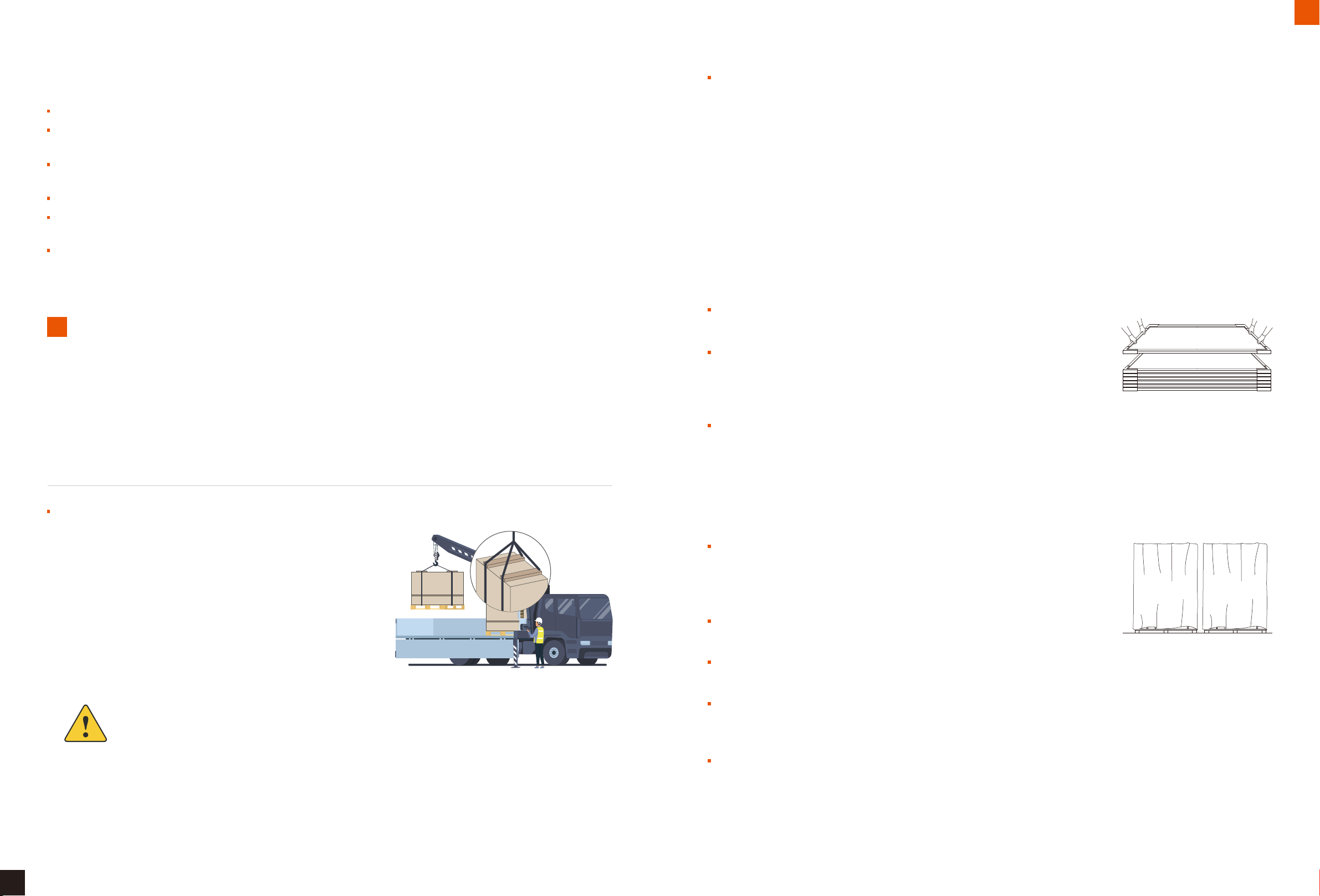
Crane unloading:
When unloading the modules by crane, please choose and use
specialized tooling according to the weight and size of the pallet.
Please adjust the position of the sling to keep the modules steady.
To ensure the safety of the module, wooden sticks, boards or other
fixtures of the same width as the outer packing cases should be
used on the upper part of the box to prevent the sling from
squeezing the pallet and damaging the modules. Please operate
the spreader at a constant speed, when the lifting is close to the
ground, place the box gently in a relatively flat ground.
Do not unload modules under the weather conditions of wind more than 6 class (in Beaufort scale)
Storage and transportation instructions
04
When using forklift to transport modules, please ensure that the fork length
meets the requirements to avoid module tilting due to uneven force.
When opening the packing box, please place the modules to be unpacked at a
distance of 20-30cm from the wall or another torr of modules, and then remove
the torr. After removing the cable tie of the fixed modules, slowly lean the
modules against the wall or another torr of modules to prevent them from falling.
Forklift unloading:
The loading dock should be as the same height as the underside of the carrier.
Keep the straight line speed of forklift within 5km/h and the turning speed within 3km/h. Please avoid sudden stop and
rapid start.
If the packing box blocks the sight of the forklift driver, it is recommended to drive backwards during the fork-lifting, and
arrange for special supervision and command to prevent bumping into people or items causing personal injury or damage
to the modules.
4.2 Considerations for module transportation
Please handle the installation modules gently during transportation, Do not lift the modules by pulling the junction box or
cables under any circumstances. Two or more people must hold the edges of the modules with both hands.
Please store the packing box of modules in a clean, dry place with relative
humidity below 85%. The storage temperature should be between -20 ℃ and
50 ℃ . When storing modules for a long time, do not place the two boxes of
modules on top of each other.
In any circumstances, keep the junction box and cables of the modules clean and
dry.
4.3 Considerations for module storage
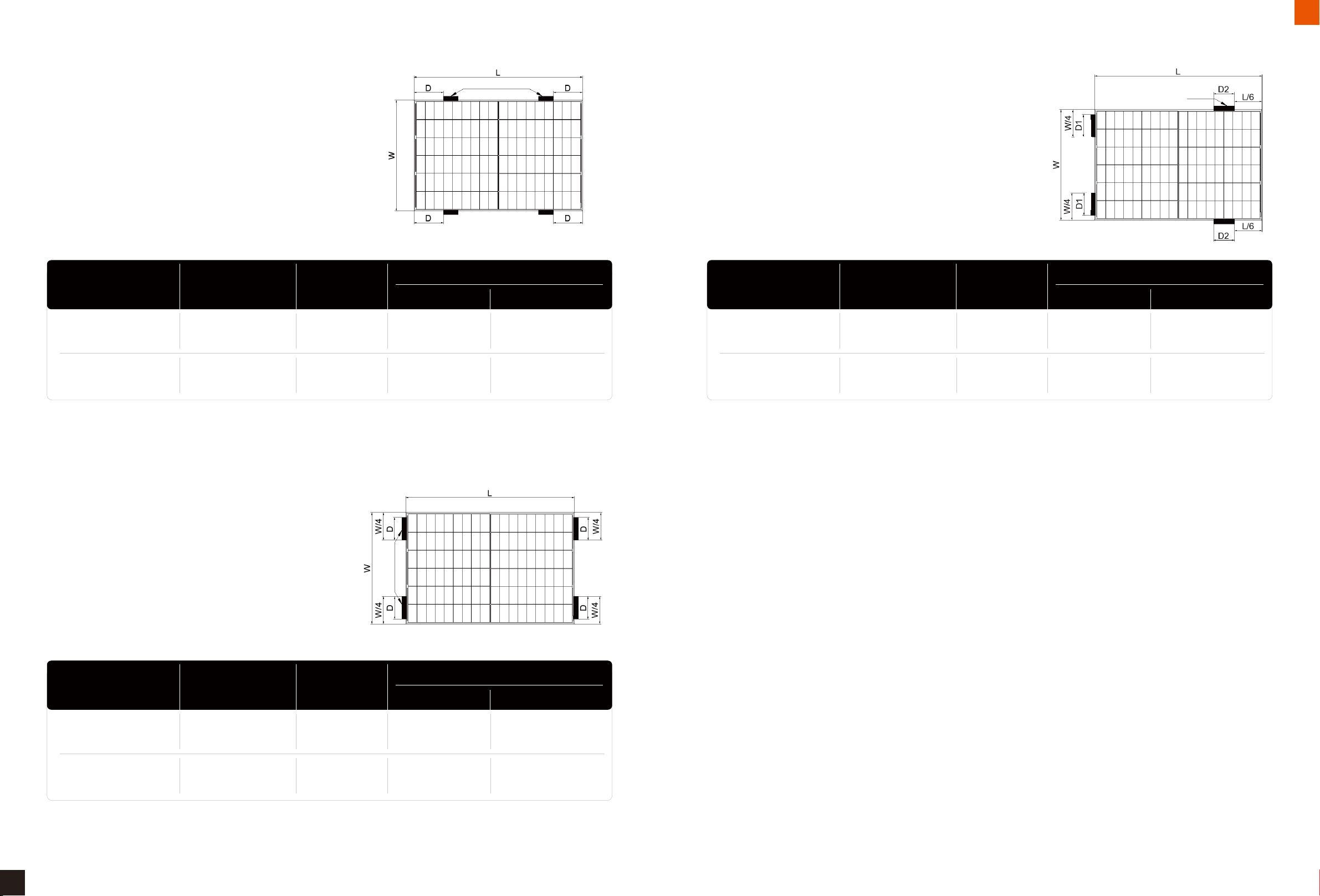
Store modules in a ventilated, rainproof, dry place, If placed outdoor, please fully cover the modules and pallets with a
rain protection and take moisture-proof measures on pallets and cartons to prevent collapse and moisture ingress.
For the storage of unpacked modules, please stack the modules flat on the empty torr. The first module should be placed
with the glass side up, and the following ones placed with the glass side down. (A maximum of 25 pieces of modules for
54 types and 20 pieces of modules for 72 types can be stacked together).
For long-term storage, do not remove the original package and keep the wrapping film and carton box in a good
condition. It' s recommended to place modules in a standard warehouse for long-term storage and conduct regular
inspections. Once there is an abnormal tilt, please take enforcement measures in time.

09/10
Installation conditions
Tilt angle of PV modules refer to the included angle between module surface and horizontal ground. Different projects shall
choose different installation inclination angles according to local conditions.
All modules in the same array shall be of the same orientation and angle. Different orientations and angles will result in
different total solar irradiation absorbed by modules, leading to output mismatch and decrease the system operating
efficiency.
In order to achieve the maximum annual generating capacity, the optimal orientation and inclination of PV modules in the
installed area should be selected. When the surface of the module is perpendicular to sunlight, the output power reach the
maximum output value. AIKO recommend the installation angle shall not less than 10 degree. The optimal tilt angle of PV
arrays shall be designed by taking into account the multi-year mean monthly irradiance, direct irradiance, scattering
irradiance, wind speed and other climate conditions at the location. PV modules should be tilted at an angle to receive the
maximal annual irradiance. Angles shall be selected by considering natural conditions such as local wind load, snow load
and avoidance of water and dust collection on module surfaces. For details on the optimal tilt angle for installation, refer to
consult a reliable local solar system installation company.
Sunlight
Tilt angle
5.1 Location and working environment
5.2 Tilt angle selection
Installation conditions
05
Modules are recommended to be installed in the working environment with the temperature of -20℃~50℃ environment.
The extreme working ambient temperature is -40 ℃~85 ℃ and a humidity less than 85%RH.
Modules are designed to operate up to 2000 m above sea level.
Do not install modules in locations where there is a risk of flooding, and do not install or place modules near open flame
or flammable materials
Modules can be installed at a distance of 50m away from the seashore. In the case when the modules are installed
within 50m to 500m distance from the seashore, the frame and related components need to be treated with
anti-corrosion.
For rooftop installations, leave a safe working area between the edge of the roof and the external edge of the PV module
array.
For rooftop installations, check the roof loads and make a construction organization plan to meet the applicable
standards.
Modules shall be positioned to receive adequate sunlight and avoid shading the module surfaces in part or in whole (by
trees, buildings, etc).
In areas (e.g. coastal areas, factories, volcanic areas, farmlands) exposed to salt fog, sulfide or ammonia gas, corrosion
can occur at the connection between the module and the racking or at the ground connection. Anticorrosive materials
(e.g., stainless steel or aluminum materials) must be used in contact with PV modules and the mounting position must be
protected against rust.
After the modules are installed, measures such as grounding must be taken to ensure that the modules are protected
against lightning strikes
Modules shall be installed in a well-ventilated
position to ensure adequate air circulation on
the back and sides of the module and allow
immediate dissipation of heat produced
during module operation, poor heat
dissipation of the modules will decrease the
output power and affect the overall power
output of modules.
When modules suffer high wind or snow
pressure, supports and fixings shall be
designed according to local design standards
to keep external loads within the maximum
mechanical strength that modules can
withstand.

11/12
Mechanical installation
Under no circumstances should the clamp touch the glass or deform the frame. Be sure to avoid shadowing effect from the
pressure clamp.
Be sure that pressure clamps will not fail due to deformation or corrosion while the entire module is under load. Pressure
clamps > 50 mm in length and >3 mm in thickness are recommended. The overlapped distance between the pressure clamp
and the module frame, D, shall be at least 7 mm but no more than 10 mm.
When choosing clamp-mounting, please be sure to use at least four clamps on each module. Depending on the local wind
and snow loads, if excessive pressure load is expected, at least six clamps should be required to ensure the module can bear
the load (more details, please contact AIKO technical personnel)
The applied value of torque should refer to mechanical design standard and the bolt type customer is using, for example:
M8: 16-20 N•m
Single glass modules can be installed using pressure clamps. Following are the installation diagram and corresponding loads.
Here, L stand for long side of module, W stand for short side of module, dark area stand for the installation area of the
clamp, D, D1 and D2 as defined in table 3, 4 and 5. Distance and length are provided in mm; pressure is provided in Pa.
The module can be mounted by a dedicated clamp, as shown below.
6.2.1 Mounting pressure clamps
6.2.2 Single glass modules clamp mounting diagram and corresponding loads
AlKO single glass modules can be connected to the mounting system using pressure clamps and bolts. Modules must be
mounted as recommended and illustrated below. Other mounting configurations may be used provided that consultation is
made with, and prior written consent is received from, Aiko Energy. Failure to do so will invalidate our warranty.
6.2 Mechanical installation of single glass modules
6.1 General requirements
Mechanical installation
06
Make sure that the modules are properly installed and the mounting structure are adequately fastened. Mounting system
shall be made from anticorrosive, ultraviolet resistant materials.
Installation bracket system shall be tested and inspected by the third party testing institution with static mechanical
analysis capacity in accordance with local national standards or international standards.
In regions with heavy snowfall in winter, adjust the height of the mounting system so that the lower edge of the module
is not covered by snow In addition, ensure the lower part of module is not in the shadow of plants, trees.
For rooftop installations, the minimum gap between the module frame and the roof shall be 10cm which is good for air
circulation to achieve better performance of module.
The minimum mounting distance between two adjacent modules shall be no less than 10 mm.
Make sure that backsheet of modules will not be in contact with bracket or building structures that can pierce into the
inside of the modules, especially when the module surface is imposed by pressure
Modules can be installed horizontally or vertically. When installing the components, be cautious not to block the drain
hole of the frame
The module loads described herein are test values. According to IEC 61215-2016 installation requirements, when
computing the corresponding maximum design load, a safety factor of 1.5 need to be considered in compliance with the
local laws or regulations. In additions, project design loads must be based on project location, climate, mounting structure
and applicable standards. Design loads are determined by mounting suppliers. Please observe both the local laws and
regulations and the instructions of structural engineers.
25(recommended)
3
5≥50
9~11
Ф8~9
5
30
Ф8~9
5
5
13
≥50
3
3
9~11
Side clamp
Bolt
Gasket
Nut
Gasket
Module
Frame
Racking
Middle clamp
Module
Frame
Gasket
Nut
Gasket
Module
Bolt
Frame
Racking

13/14
Mechanical installation
Installation area D
30mm frame 35/40mm frame
Module model Module size [mm] Load [Pa]
AIKO-A***-MAH54Mw
AIKO-A***-MAH54Mb
AIKO-A***-MAH72Mw
AIKO-A***-MAH72Mb
295≤D≤395
380≤D≤480
1722*1134
2278*1134
350≤D≤450
400≤D≤500
+5400/-2400
+5400/-2400
Table 3: Single glass modules clamp mounting diagram and corresponding loads, long frame (A)
(B)CLAMP MOUNTING - SHORT FRAME
clamp mounting on short frame
area
Installation area D
30mm frame 35/40mm frame
Module model Module size [mm] Load [Pa]
AIKO-A***-MAH54Mw
AIKO-A***-MAH54Mb
AIKO-A***-MAH72Mw
AIKO-A***-MAH72Mb
D=W/4-100
/
1722*1134
2278*1134
D=W/4-50
/
+1600/-1600
/
Table 4: Single glass modules clamp mounting diagram and corresponding loads, short frame (B)
clamp mounting on short&long frame
area
(C)CLAMP MOUNTING - SHORT & LONG FRAME
Installation area D
30mm frame 35/40mm frame
Module model Module size [mm] Load [Pa]
AIKO-A***-MAH54Mw
AIKO-A***-MAH54Mb
AIKO-A***-MAH72Mw
AIKO-A***-MAH72Mb
D1=W/4-100
D2=100
/
D1=W/4-50
D2=120
/
1722*1134
2278*1134
+2400/-2400
/
Table 5: Single glass modules clamp mounting diagram and corresponding loads, short & long frame (C)
clamp mounting on long frame
area
(A)CLAMP MOUNTING - LONG FRAME
Note: The above data is based on the static load requirements of IEC61215 standard

Single glass modules bolt mounting diagram and corresponding loads as below diagram.
6.2.4 Single glass modules bolt mounting diagram and corresponding loads
15/16
Mechanical installation
(D)BOLT MOUNTING - TRANSVERSAL
Table 6: Single glass modules bolt mounting diagram and corresponding loads, transversal (D)
Note: The above data is based on the static load requirements of IEC61215 standard
It is important to ensure the bolts do not fail due to deformation or corrosion during the overall load of the module. AIKO
recommend the thickness of washer should ≥1.7mm and use M8 nut and bolt, the tightening torque should be between
16-20 Nm depending on the bolt grade.
No. Accessories
Bolt
Spring washer
Washer
Bracket
Washer
Nuts
1
2
3
4
5
6
Model
M8*1.25
13.5*2.1
16*1.7
/
16*1.7
M8*1.25
Material
S35C
Mn65
Fe
Q235
Fe
S35C
16
8.5
1.7
M8X1.25
6.25±0.25
3 5 6
16
8.5
1.7
Using bolts to secure the module on the bracket through the mounting holes. Modules come standard with 4 or 8 mounting
holes, matching M8 bolts, as figure below:
6.2.3 Bolts Mounting
5.0
Bolt
M8X1.25
13.5
2.1
1 2
25
31
13
Washer
Bracket
Washer
Nut
Aluminum frame
Spring washer
Module model
Load [Pa]
Module size
[mm]
1722*1134
2278*1134
AIKO-A***-MAH54Mw
AIKO-A***-MAH54Mb
AIKO-A***-MAH72Mw
AIKO-A***-MAH72Mb
4 inner
mounting holes
+5400/-2400
/
Frame thickness
[mm]
30/35/40
30/35/40
4 outer
mounting holes
+2400/-2400
+5400/-2400
The beam perpendicular to the long frame
(E)BOLT MOUNTING - LONGITUDINAL
Table 7: Single glass modules bolt mounting diagram and corresponding loads, longitudinal (E)
Module model
Load [Pa]
Module size
[mm]
1722*1134
2278*1134
AIKO-A***-MAH54Mw
AIKO-A***-MAH54Mb
AIKO-A***-MAH72Mw
AIKO-A***-MAH72Mb
4 inner
mounting holes
+5400/-2400
/
Frame thickness
[mm]
30/35/40
30/35/40
4 outer
mounting holes
+2400/-2400
+5400/-2400
The beam perpendicular to the short frame

17/18
Mechanical installation/Electrical installation
The electrical performance parameters of AlKO modules are detailed in the product specification. Standard test conditions
(STC) for PV modules: irradiance 1,000 W/m²; a cell temperature 25 ℃; AM1.5. The maximum system voltage of AIKO
modules is 1,500 V.
When modules are in series connection, the string voltage is sum of every individual module in one string. When modules are
in parallel connection, the current is sum of the individual modules as shown below. Modules connected in the same string
shall have the same product code and nominal power.
If there has reverse current exceeding the maximum fuse current flowing through the module, use overcurrent protection
device with the same specifications to protect the module. If more than two strings are connected in parallel, there must be
an overcurrent protection device on each strings of module.
The string voltage must not exceed the maximum voltage that the system can withstand or the maximum input power of
the inverter or other electrical devices installed in the system. To ensure this, the open circuit voltage of the array shall be
calculated at the minimum expected ambient temperature at that location. The following formula may be used:
Where:
N
Voc
β
Tmin
7.1 Electrical performance
Electrical installation
07
AIKO 72 type modules come standard with four mounting holes matching M8 bolts (As shown in the figure below, the dotted
box is marked that the four M8 bolt mounting holes are all outer four holes); 72 type modules have additional four mounting
holes matching M6 bolts (the circle is marked in the figure below) used for matching tracking system product. Using bolt to
install the module on the bracket through the mounting hole. Installation details as below:
6.2.5 Single-axis tracking system installation
4 outer M8
mounting hole
4 inter M8
mounting hole
1400±1
1084±1
400±1
Parallel after series connection
Diode
Connector
Overcurrent protective device
Series connection
Maximum system voltage ≥N×Voc×[1+β*(Tmin-25)]
number of modules connected in series
open circuit voltage of each module (refer to product nameplate or specification) [V]
thermal coefficient of open circuit voltage for the module (refer to the specification) [°C-1]
lowest ambient temperature [°C]

Following is the recommended grounding method:
Unused module mounting holes on the frame may
also be used for grounding purposes.
We recommend torquing grounding bolts to 3~7 Nm
and using 4 mm2 copper wires as grounding wires.
There are φ4.2 mm grounding holes on surface C of the module frame. Use a separate grounding wire and
accessories to connect the aluminum alloy frame of PV modules and connect the grounding wire to the ground. We
recommend using M4×12 mm grounding bolts accompanied by M4 nuts, star washers and flat washers.
Connection mode: the star washer, flat washer, and ground wire are placed in sequence, threaded through the
ground hole using screws, and tightened to secure the adjacent modules.
Modules are designed with an anodized anticorrosive aluminum alloy frame as a rigid support. Module frames must be
grounded to ensure safe use and protect the module against lightning and electrostatic damage. Grounding must be made
with the grounding device in full contact with the interior of the aluminum alloy and penetrating the oxide film on the frame
surface.
Grounding devices include grounding screws, flat washers, puncture gaskets and grounding wires. All these items shall be
constructed of stainless steel except grounding wires. Grounding wires shall be copper wires. Grounding conductors shall be
connected to the ground through an appropriate grounding electrode. Third-party grounding devices meeting local electrical
installation standards at the location may be used for grounding AIKO modules. Grounding device shall be installed
according to the operation manual provided by the manufacturer.
Grounding
08
19/20
Electrical installation/Grounding
PV module’ s junction boxes with the IP68 protective level and composed of connected cables and IP68 connectors. The
module has a positive and a negative PV wires connected into the junction box and a plug-and-play connector connected at
the other end. Using the positive connector of the module to connect the negative connector of the adjacent module
connects the two modules in series.
Use specialized solar wires and appropriate connectors according to local electrical and installation standards, codes and
regulations at the location, and ensure that the electrical and mechanical properties of the cables are good. AlKO modules
use specialized PV cables which have a cross sectional area of 4 mm² and are ultraviolet resistant. AIKO recommends that
all cables are run in appropriate conduits and sited away from areas prone to water collection.
AIKO recommend use standard PV copper wires with a cross-section area of 4 mm², temperature-resistant at a minimum of
90 ℃, and with UV resistant. The minimum bending radius of the cable is 43mm.
7.2 Cables and Connections
Take care to keep the connectors dry and clean. Make sure that the connector nuts are tightened before making any
connection. Do not connect while the connectors are wet or otherwise abnormal. As connectors provide IP68 protection only
when the positive and negative poles are fully mated, please connect modules as soon as possible after installation or take
proper steps to prevent water vapor and dust from coming into the connector.
Avoid exposing the connector to direct sunlight and water. Avoid exposing the connector directly to ground surface or roof.
Make sure that all electrical connections are secure. Incorrect connection can result in electrical arcing and shocks.
Do not mate different models of connectors together.
7.3 Connector
grounding
hole

The power output of modules is related to incident light intensity and can be reduced by dust collection or other shadings.
Dirt on modules must be cleaned up immediately.
The cleaning frequency depends on the degree of dirt collection. Modules installed at an adequate tilt angle will allow
rainwater to clean the module surfaces, thereby reducing the cleaning frequency.
9.1 Cleaning
Modules shall be inspected and maintained on a regular basis; during the warranty period it is an obligatory responsibility of
the user. Any damage or other visible abnormalities of the module shall be reported to AIKO customer service upon
discovery.
Maintenance of PV modules
09
21/22
Grounding/Maintenance of PV modules
Method A: High pressure water cleaning
We recommend using the following method to ground correctly, as shown in the figure.
Components Sketch map
Connection bolt and notch
Washer faced hex nut
Aluminum
frame
Cable hole
Hex nut
Sliding
block Bolt
Nut
Trunking
Base
Water Absolute ethtl
alcohol
Dust-free
gloves
Dust-free
paper
Water quality requirement
PH:6-8
Water hardness - calcium carbonate concentration: <600mg/L
Recommended use of soft water cleaning
Recommended maximum water pressure is 4MPa (40bar)
Method B: Compressed air cleaning
Air pressure cleaning is recommended when cleaning soft
stains (like dust) on modules.
Method C: Wet test cleaning
If there is too much stain on the surface of the module, it's recommended to carefully use an insulating brush, sponge or
other soft cleaning tool.
Ensure that any brushes or agitating tools are made of insulating material to minimize the risk of electric shock and that
they do not scratch the glass or aluminum frame.
For oil stains, it' s recommended to use an environmentally friendly cleaner.
Method D: Robot cleaning
If there is too much stain on the surface of the module, it's recommended to carefully use an insulating brush, sponge or
other soft cleaning tool.
Ensure that any brushes or agitating tools are made of insulating material to minimize the risk of electric shock and that
they do not scratch the glass or aluminum frame.
For oil stains, it' s recommended to use an environmentally friendly cleaner.
We recommend cleaning the glass surface of the module with a clear water-wetted sponge. Do not clean modules with a
detergent containing acid or alkali. Do not clean modules with rough surface tools.
We recommend cleaning modules in the early morning or late afternoon or other periods of time when the light is weak and
the module temperature is comparatively lower.

23/24
Maintenance of PV modules
Visually checks for visual defects on modules, such as:
9.2 Visual checks of the modules
Whether the module glass is broken;
Whether the back cover of the module is cracked or otherwise abnormal;
Whether the junction box is damaged or the cable is broken;
Whether the module is shaded by foreign matter or shadows;
Check whether the bolts fixing the module to the racking are loose or corroded and adjust or replace them if necessary;
Check whether the modules are well-grounded
It is recommended to perform preventive examinations every six months, such as:
9.3 Checks of connectors and cables
Whether the connectors are properly sealed and the cables are properly fastened;
Whether the sealant of the junction box is cracked.
In order to request Technical Support:
9.4 AIKO Technical Support
Collect evidences of the issue as (a) photos and (b) measurements
Be prepared to show the purchase invoice and module serial number
Contact your Installer
This manual suits for next models
4
Table of contents
Popular Solar Panel manuals by other brands

Sygonix
Sygonix SY-VRU214-2 operating instructions

boviet SOLAR
boviet SOLAR Vega BVM7612M H-HC-BFDG Series Installation and maintenance manual

VTOMAN
VTOMAN VS110 user manual

Kyocera
Kyocera KD235GX-LPB datasheet

Thunderbolt
Thunderbolt 63585 Owner's manual and safety instructions

Sferasol Energy
Sferasol Energy SFERASOL SF-S Use and maintenance