esera automation ESERA-Station 200 User manual
Art. No. 19200
All rights reserved. Reproduction as well as electronic duplication of this user guide, complete or in part, requires the written consent of
ESERA GmbH. Errors and technical modification subject to change. ESERA GmbH, ESERA-Automation 2020
www.esera.de 19200 V2.0 R1.0 Manual Page 1 of 10
User Guide
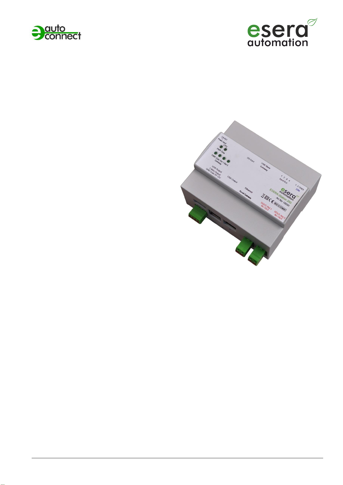
ESERA-Station 200
Central hard- and software control (system-open)
for smart home, building automation, IoT and
commercial automation
Hybrid construction consisting of Embedded
Computer and 1-Wire Gateway
Powerful, modern quad core computer with 1.4GHz
CPU speed
Fast reading of all 1-Wire devices within 1-2
seconds
Data exchange among 1-Wire Gateway and
computer via Modbus or text protocol
Large 1-wire libraries for sensors and actuators
2 x binary output 16A
2 x binary input 10-30VDC
2 x System clocks with power-failure buffering
Convenient configuration program for 1-Wire
Gateway and interface parameters
24V power supply for Embedded Computer and
1-Wire gateway
Designed for all sizes of 1-Wire Networks
Top-hat rail case for switchboard assembly
1 Introduction
Before you start assembling the ESERA-Station 200 and before you take the device into operation, please
read this assembly and operating instruction carefully to the end, especially the section referring to the safety
notes.
2 Product description
The ESERA-Station 200 is a modern and system-open hybrid system consisting of two modules, a powerful
1-Wire gateway and an Embedded Computer.
Both modules are internally connected by a serial data interface and the power supply.
Each module has an own power supply and a system clock (real time clock) with power-failure buffering by a low-
maintenance, high-performance capacitor (Goldcap).
2.1 Embedded Computer
The ESERA-Station 200 includes a standardized and powerful computer that comes with a
Quad Core CPU with 1400MHz. This CPU provides enormous power reserves by low power consumption. Given
to its 1024 MB RAM memory, even large automation projects can be implemented.
All modern interfaces such as LAN, WLAN with 2.4GHz and 5GHz, as well as Bluetooth with standard 4.2 are
available for connection with the "outside world".
The Embedded Computer also has 3 external and one internal USB 2.0 interfaces.

All rights reserved. Reproduction as well as electronic duplication of this user guide, complete or in part, requires the written consent of
ESERA GmbH. Errors and technical modification subject to change. ESERA GmbH, ESERA-Automation 2020
www.esera.de 19200 V2.0 R1.0 Manual Page 2 of 10
2.2 1-Wire Gateway
In addition to the Embedded Computer, the ESERA-Station 200 has an extremely powerful and reliable 1-Wire
interface, the 1-Wire Gateway developed by ESERA.
The 1-Wire Gateway is internally connected to the Embedded Computer by serial interface. Via an USB slave
interface, the 1-Wire Gateway can also be accessed directly, without an Embedded Computer. Once you use the
USB interface, the internal communication to the Embedded Computer is interrupted. The Embedded Computer
is only able to receive data.
Standard Modbus TCP protocol
You can work with your industrial controller, e.g. SPS to communicate with the 1-Wire Gateway 20 via
standard Modbus TCP protocol. The addressing is structured in a way that is comparable to many other
Modbus systems. Addresses for system and sensor or actuator data are available.
An address overview with all available data points is available at the article download section of our website.
Independent administration
The ESERA-Station 200 is intended for self-sufficient management of 1-Wire networks. You no longer have
to worry about 1-Wire commands or formulas for evaluating sensor data. The ESERA-Station 200
independently scans the 1-Wire network for new sensors and actuators and makes them available, in plain
text by using Modbus protocol, depending on the modules found and the corresponding data converted.
Formatted data output
The ESERA-Station 200 provides plausibility checked sensor and actuator data in a ready to use format. E.g.
temperature sensor provides values in Celsius degrees with 2 decimal places. You only need to divide this
number by 100. Within the 1-Wire Gateway a product specific transformation table is available for all 1-Wire
sensor and actuator products offered by ESERA.
Designed for all 1-Wire Networks
The 1-Wire interface of the ESERA-Station 200 is specially designed to securely support all sizes of 1-Wire
networks, even for huge cable length. 1-Wire sensor devices can be operated in parasitic or normal mode at
the same time.
The latest available most powerful 1-Wire interface for a maximum level of data security has been used. This
includes complex network structures as well.
1-Wire Gateway configuration
Free configuration software (Config-Tool 3) is provided. When using Config-Tool 3, the latest documentation
is available at any time hence it automatically updates via internet. This software is available for download on
our webpage. Communication to Modbus TCP is parallel with no switching.
System time / real time clock
No real time clock with battery buffering available in your system? No problem at all. ESERA-Station 200 is
providing time and date as real time clock including an integrated backup battery. Data plausibility check is
possible at any time.
Power supply
The ESERA-Station 200 is supplied with the industrial 24V voltage.
Connection
Standard connectors are provided for USB and Ethernet connections. All other connectors are designed in
modern screwless push-in technology for rigid and fine-stranded cables with cross sections up to 1.5 or
2.5qmm.
Input voltage for the ESERA-Station 200 is 16 –30 VDC. Therefore it can be used for 24 VDC (industrial
applications). Appropriate hat-rail mounted power supplies or power plugs can be found in our webshop.
3 Auto-E-Connect® Support
The ESERA Auto-E-Connect® 1-Wire Plug and Play system will be used for the
1-Wire Bus supported. This enables fully automatic configurations of 1-Wire sensors
and actuators on the 1-Wire bus. It is optimized for industrial applications and
enables significant added value beyond the sensor and chip data.

Art. No. 19200
All rights reserved. Reproduction as well as electronic duplication of this user guide, complete or in part, requires the written consent of
ESERA GmbH. Errors and technical modification subject to change. ESERA GmbH, ESERA-Automation 2020
www.esera.de 19200 V2.0 R1.0 Manual Page 3 of 10
The Auto-E-Connect function automatically recognizes ESERA chips, sensors and actuators, starts suitable
libraries and outputs fully formatted data.
The Auto-E-Connect functionality will be available from mid-2020 via 1-Wire Controllers, 1-Wire Gateways and
1-Wire ECO from ESERA available.
Further information on ESERA Auto-E-Connect can be found on the ESERA website, ESERA Config-Tool 3, or in
the download area for this article in the ESERA Webshop.
4 Technical data
Embedded Computer
CPU: Quad-Core processor ARM-Cortex-A53 64Bit, 1400 MHz
Memory: RAM 1024 MB LPDDR2 memory
microSD card 8GB for operating system and software application
Operating system: Linux Debian (Raspian), software already installed
Software, option: - IP-Symcon, basic, professional or unlimited
- Codesys 3.x
External interface: LAN RJ45 10/100/1000 Mbit (Gigabit LAN by USB 2.0 with up to 300 Mbit)
- Auto negotiation (full-duplex and half-duplex)
- Support for DHCP and IP-address
- DNS support
- Auto MDI/MDIX
WLAN 802.11 b/g/n/ac (2,4 + 5,0 GHz)
Bluetooth 4.2
System clock (RTC): DS1307 with ability to bypass power failure with Goldcap for min. 24 hours
1-Wire Gateway
Data interface: Modbus RTU and ESERA ASCII text protocol
Internal interface: serial, 19200 baud 8 data bit, 1 start bit, no stop bit
Firmware update and
configuration by ESERA Config-Tool 3
1-Wire interface: 1-Wire bus (Masse/GND, 5V, 12V and data)
Protection circuits: ESD- and reverse polarity protection
Connection: Push In connector for cables up to 1.5qmm cable cross section
Output voltage: 5V max. 1A, 12VDC max. 1,2A
Overload and short circuit proof
Digital- /binary input: 2 x input 10-30VDC, max. 10mA per channel
isolated with common negative pole
Push In connector for cables up to 1.5qmm cable cross section
Digital- /binary output: 2 x output (relays) 16A switching current (NO), isolated
Push In connector for cables up to 2.5qmm cable cross section
System clock (RTC): DS1307 with ability to bypass power failure with Goldcap for min. 24 hours
Entire system
Power supply: 16 –30 VDC
Input: 3,4 –38W*
* depending on the CPU load and load on the 1-wire interface
5 Ambient conditions
Temperature, operation -10 °C up to +55 °C (extended temperature range available upon request)
Air humidity: 10 –92 % (non-condensing)
Protection system: IP20
Protection class: III
Dimensions: 35 x 90 x 70mm (WxHxD)

All rights reserved. Reproduction as well as electronic duplication of this user guide, complete or in part, requires the written consent of
ESERA GmbH. Errors and technical modification subject to change. ESERA GmbH, ESERA-Automation 2020
www.esera.de 19200 V2.0 R1.0 Manual Page 4 of 10
6 Conformity
EN 50090-2-2
EN 61000-4-2, ESD
EN 61000-4-3, HF
EN 61000-4-4, Burst
EN 61000-4-5, Surge
EN 61000-6-1, Fault-free operation
EN 61000-6-3, Stray radiation
RoHS
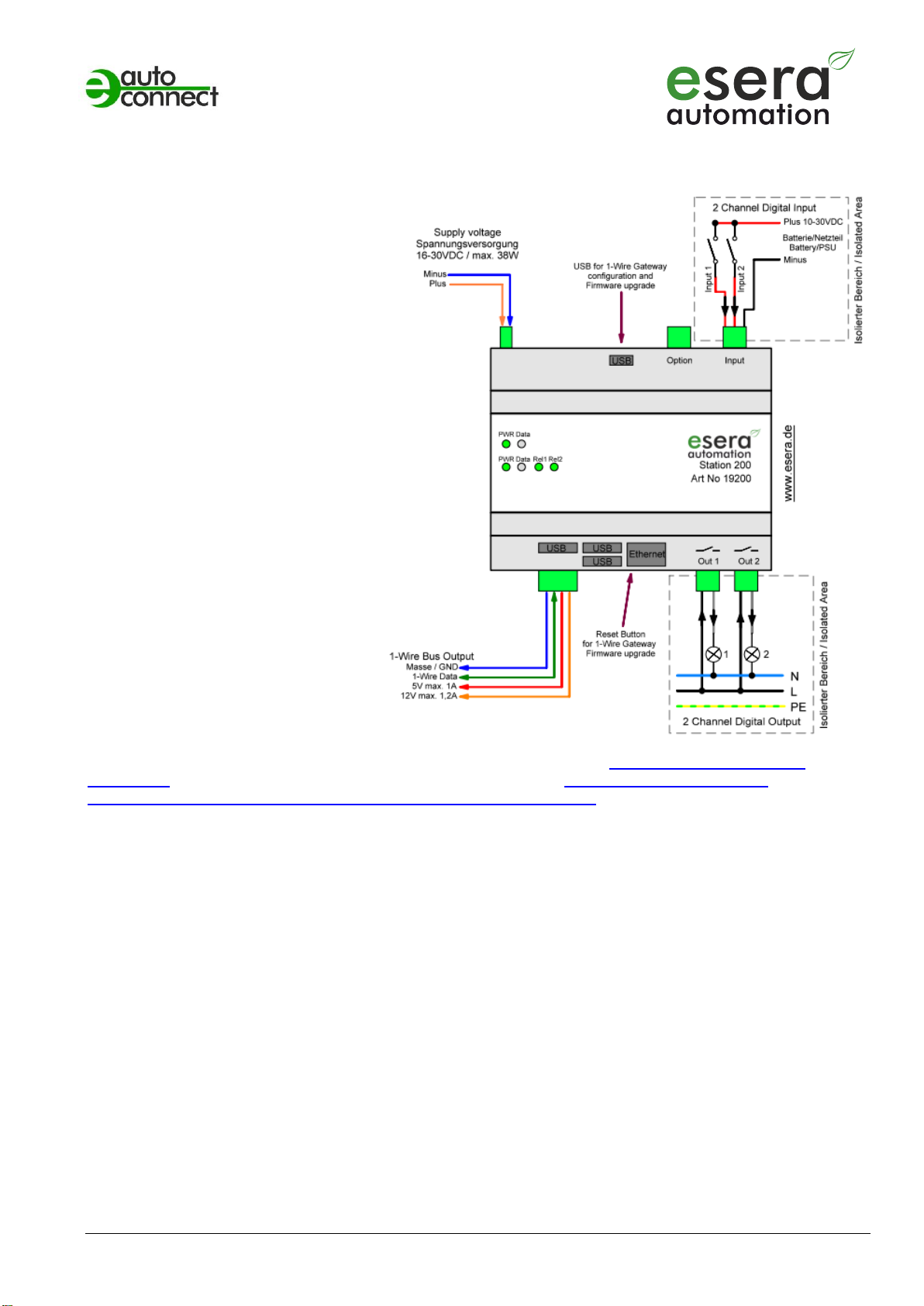
7 Block diagram
8 LED display
The ESERA-Station 200 has various display LEDs. Please refer to the following table for their functions:
LED Status
Description
Function
Embedded Computer
LED green front
PWR
Display supply voltage Embedded Computer
LED green front
DATA
LED, can be programmed for individual use (GPIO 27)
LED green Ethernet
DATA
Flashes while transferring data
LED green Ethernet
LINK
Is lit if Ethernet connection is active
1-Wire Gateway
LED green
PWR
Display supply voltage 1-Wire Gateway
LED green
DATA
LED flashes 3 times after power on
Flashes at 1-Wire activity
Flashes while transferring data by the data interface
Flashes rapidly if "KAL Receive" has been activated no
“KAL messages" received.
LED green
REL1
Output 1, is lit when relay 1 is active
LED green
REL2
Output 2, is lit when relay 1 is active
Art. No. 19200
All rights reserved. Reproduction as well as electronic duplication of this user guide, complete or in part, requires the written consent of
ESERA GmbH. Errors and technical modification subject to change. ESERA GmbH, ESERA-Automation 2020
www.esera.de 19200 V2.0 R1.0 Manual Page 5 of 10
9 Connection
Module top side (left to right)
Supply voltage 16-30VDC
USB Slave for 1-Wire Gateway
Configuration and firmware
update/upgrade
Optional input (not equipped)
2 x digital input 10-30VDC isolated
Module bottom side (left to right)
lower level
1-Wire bus output, Masse/GND, Data,
5V (max. 1A) and 12V (max. 1,2A)
Reset button for 1-Wire Gateway (inside)
Digital output 1 (max. 16A)
Digital output 2 (max. 16A)
upper level
3 x USB output (5V max. 0,5A)
Ethernet input RJ45
10/100/1000 MBit
Note: Basics and tips for 1-Wire bus systems can be found in our webshop (https://www.esera.de/1-wire-
grundlagen/) or in our e-book which is also available in our webshop (https://www.esera.de/service-
support/dokumentation/352/grundlagen-1-wire-bus-ebook?number=11901).
Other manuals for ESERA-Station 200
2
This manual suits for next models
1
Table of contents
Other esera automation Recording Equipment manuals


