esera automation ESERA-Station 200 User manual

Art. Nr. 19200 Linux
All rights reserved. Reproduction as well as electronic duplication of this user guide, complete or in part, requires the written consent of
ESERA GmbH. Errors and technical modification subject to change. ESERA GmbH, ESERA-Automation 2020
www.esera.de 19200 V1.0 R1.0 Commissioning II Page 1 of 9
ESERA-Station 200
Commissioning II
Linux Manual
Open system hardware and software central
control for smart home,
building automation, IoT and commercial
automation
Hybrid structure consisting of embedded
computer
and 1-Wire gateway
Powerful, modern quad core computer with
1.2GHz CPU speed
Fast readout of all 1-Wire devices in
1-2 seconds cycle
Data exchange between 1-Wire Gateway
and Computer via Modbus or text protocol
Extensive 1-Wire libraries for sensors and
actuators
2 x binary output 16A
2 x binary input 10-30VDC
2 x system clocks with power failure buffer
Comfortable configuration program for 1-Wire
Gateway
and interface parameters
24V power supply for embedded computer
and 1-Wire Gateway
Designed for all 1-Wire network sizes
Top-hat rail housing for control cabinet
installation
1 Introduction
Before you start to install the ESERA-Station 200 and put the device into operation, please read through this
operating manual until the end, especially the section on safety instructions
2 Produkt description
The ESERA-Station is a modern and open-system hybrid system consisting of two modules, a powerful
1-Wire Gateway and an embedded computer.
Both modules are connected internally via serial data interface and the power supply.
Each module has its own power supply unit and a system clock (real time clock) with power failure buffering by a
low-maintenance high-performance capacitor (gold cap).
3 IP-Adressen
On delivery, the ESERA-Station is set to DHCP for LAN and WLAN Interface.
All rights reserved. Reproduction as well as electronic duplication of this user guide, complete or in part, requires the written consent of
ESERA GmbH. Errors and technical modification subject to change. ESERA GmbH, ESERA-Automation 2020
www.esera.de 19200 V1.0 R1.0 Commissioning II Page 2 of 9
4 Commissioning
Please start with the commissioning of ESERA-Station 200 with the 1-Wire Gateway. To do so, connect to the
Config Tool 3 via USB cable, which you can download from our website.
Here you can find the Config Tool 3: https://www.esera.de/produkte/software/downloads-firmware-1-wire-
controller-1-wire-gateway/
Important:
Please start updating the time and date when
commissioning the 1-Wire Gateway.
For more details on commissioning, please refer to
the "How To" videos on our website, here:
https://www.esera.de/service-support/how-to-
support-videos/
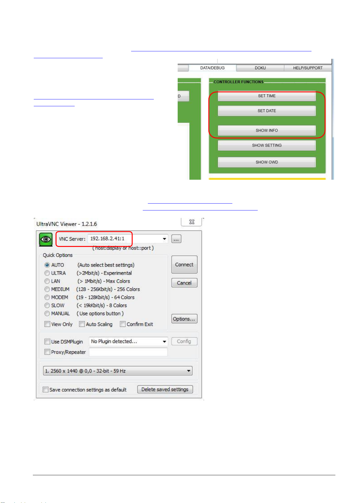
5 VNC Access
You can access the ESERA-Station directly via VNC. The thinghtvnc is pre-installed on the ESERA-Station.
For access via PC, we recommend the free UltraVNC.
Here you can find the Ultra VNC Software: http://www.uvnc.com/home.html
You can find installation instruction here: http://www.uvnc.com/install/installation.html
Access data:
To connect tot he ESERA-Station, enter the
IP-Adress and „:1“
(IP-Adress:1)
Password: eseravnc
The resolution is fixed at 1280x800 by default.
After you have logged in, please assign a new
own password..
New password for VNC access:
Start the LX Terminal and enter the
command:
vncpasswd
6 Access data
The following are the access data for accessing the Linux operating system
User: pi
Password: esera
SSH Acces
User: pi
Password: eserassh

Art. Nr. 19200 Linux
All rights reserved. Reproduction as well as electronic duplication of this user guide, complete or in part, requires the written consent of
ESERA GmbH. Errors and technical modification subject to change. ESERA GmbH, ESERA-Automation 2020
www.esera.de 19200 V1.0 R1.0 Commissioning II Page 3 of 9
7 Configuration Linux general
Within the ESERA-Station, the Debian-based Raspian operating system is used at delivery. A very good
general description for the configuration of the Linux Raspian already exists in the Web, e.g. here:
http://www.raspifun.de/viewtopic.php?t=4
8 Further information on system programming
The following information is only intended for technically experienced persons who are aware of the effects
of their actions. We do not guarantee the correctness of the explanations and the system stability. Any
changes are made at your own risk.
8.1 Installation VNC Server
Start the Installation with:
sudo aptitude install tightvncserver
After Installation, please start the Server:
tightvncserver
Assign a password for access. (optional for the view access)
vncpasswd
If you now want to access the ESERA-Station 200 remotely via VNC, a session must first be started there.
This is done by entering:
vncserver :1 -geometry 1200x800 -depth 24
8.2 VNC Server via Autostart
Start Installation:
sudo aptitude install tightvncserver
After installation, start the VNC server with the following command::
tightvncserver
Assign a password for the access. (optional for the view access)
vncpasswd
If you now want to access ESERA-Station 200 remotely via UltraVNC, you must first start a session there.
vncserver :1 -geometry 1200x800 -depth 24
Set up Autostart, create Autostart file :
nano /home/pi/.config/autostart/tightvnc.desktop
Enter in Autostart file
[Desktop Entry]
Type=Application
Name=TightVNC
Exec=vncserver :1
StartupNotify=false
Save and exit with CTRL+O, CTRL+X.
Command to end the VNC session:
vncserver -kill : 1

All rights reserved. Reproduction as well as electronic duplication of this user guide, complete or in part, requires the written consent of
ESERA GmbH. Errors and technical modification subject to change. ESERA GmbH, ESERA-Automation 2020
www.esera.de 19200 V1.0 R1.0 Commissioning II Page 4 of 9
8.3 Autostart of VNC Server via systemd-Service
To start the TightVNCServer automatically at boot time, the systemd service is required. This variant of the VNC
start has the advantage that you can control it a bit more finely, if you dare to do so from the command line.
First we create a new file in the systemd system directory:
sudo nano /etc/systemd/system/vncserver@.service
The content of the file looks like this::
[Unit]
Description=VNC mit TightVNCServer
After=syslog.target network.target
[Service]
Type=forking
User=pi
PAMName=login
PIDFile=/home/pi/.vnc/%H:%i.pid
ExecStartPre=-/usr/bin/vncserver -kill :%i > /dev/null 2>&1
ExecStart=/usr/bin/vncserver -depth 24 -geometry 1280x800 :%i
ExecStop=/usr/bin/vncserver -kill :%i
[Install]
WantedBy=multi-user.target
In the line beginning with "ExecStart..." there are the VNC parameters "-depth" and "-geometry", which can be
adjusted as desired.
Then save and close the file: Ctrl + O, Return, Ctrl + X.
Then you have to tell systemd that there is a new service/daemon.
sudo systemctl daemon reload
The following commands explain how to control this VNC service on the command line
Start VNC-Service
Stop running VNC-Service
sudo systemctl stop vncserver@1.service
Show Status VNC-Service
sudo systemctl status vncserver@1.service
Enable automatic startup at boot-up
sudo systemctl enable vncserver@1.service
Disable automatic startup on boot:
Display whether the VNC service is started automatically at boot time:

Art. Nr. 19200 Linux
All rights reserved. Reproduction as well as electronic duplication of this user guide, complete or in part, requires the written consent of
ESERA GmbH. Errors and technical modification subject to change. ESERA GmbH, ESERA-Automation 2020
www.esera.de 19200 V1.0 R1.0 Commissioning II Page 5 of 9
8.4 System clock Installation
The following system configurations are necessary to integrate the ESERA-Station System Clock (type
DS1307) into the Raspian.
Please note that the system clock is already installed at delivery.
Add Hardware Clock DS1307
Start the LX Terminal and enter he following commands:.
sudo apt-get update && sudo apt-get upgrade --yes
sudo apt-get install i2c-tools
Afterwards the I2C bus must be activated, if not already done:
sudo raspi-config
Under "Advanced Options" > "I2C" activate everything (just confirm with Yes). A restart may be necessary.
Now we edit the modules file:
sudo nano /etc/modules
and add the non-existent entries at the end:
i2c-bcm2708
i2c-dev
rtc-ds1307
To save and quit, press CTRL+O, CTRL+X
To activate the modules, they must be loaded:
sudo modprobe i2c_bcm2708
sudo modprobe i2c_dev
sudo modprobe rtc-ds1307
We can now see if the RTC module was recognized by I2C (the parameter -y 1 indicates that it is Rev.2 of
the embedded computer (Raspberry Pi).
i2cdetect -y 1
You should see the following output:
pi@raspberrypi:~ $ i2cdetect -y 1
0 1 2 3 4 5 6 7 8 9 a b c d e f
00: -- -- -- -- -- -- -- -- -- -- -- -- --
10: -- -- -- -- -- -- -- -- -- -- -- -- -- -- -- --
20: -- -- -- -- -- -- -- -- -- -- -- -- -- -- -- --
30: -- -- -- -- -- -- -- -- -- -- -- -- -- -- -- --
40: -- -- -- -- -- -- -- -- -- -- -- -- -- -- -- --
50: 50 -- -- -- -- -- -- -- -- -- -- -- -- -- -- --
60: -- -- -- -- -- -- -- -- 68 -- -- -- -- -- -- --
70: -- -- -- -- -- -- -- --
So the module is recognized and can be queried with i2cget -y 1 0x68. Because a hex code is hard to read,
we enter the module as a new I2C device:
sudo bash
echo ds1307 0x68 > /sys/class/i2c-adapter/i2c-1/new_device
exit
Then we can simply read the time with
sudo hwclock -r
The local time of the system is displayed with "date". Possibly the system clock is not yet set correctly. The
default setting is January 1, 2000. Since the local system time is correct (automatically taken from an NTP
server), you can synchronize as follows
sudo hwclock --set --date="$(date "+%m/%d/%y %H:%M:%S")"
Other manuals for ESERA-Station 200
2
This manual suits for next models
2
Table of contents
Other esera automation Recording Equipment manuals


