EsiWelma Sensigas UCE18 User manual
EsiWelma® s.r.l. E191.604_En Rev. 4 dated 30/11/2018 Pag. 1/4
EsiWelma® s.r.l.
E191.604_En
it
Istruzioni di installazione Centralina rivelazione fughe gas Sensigas®
UCE18
en
Installation instructions Gas leak detection system
fr
Instruction de installation Système de détection de fuite de gaz
en
English
These instructions must be kept together with the device.
General Information
The installation, the periodical inspections, or the devices
replacement must be done by qualified technicians.
The installation of a gas leak detection system for methane or
liquid petroleum gas (LPG), do not exempt from the compliance
to the safety rules and to all the laws in force concerning the
installation and the use of gas-operating-devices, for the
ventilation of the rooms and for the discharge of flue gases.
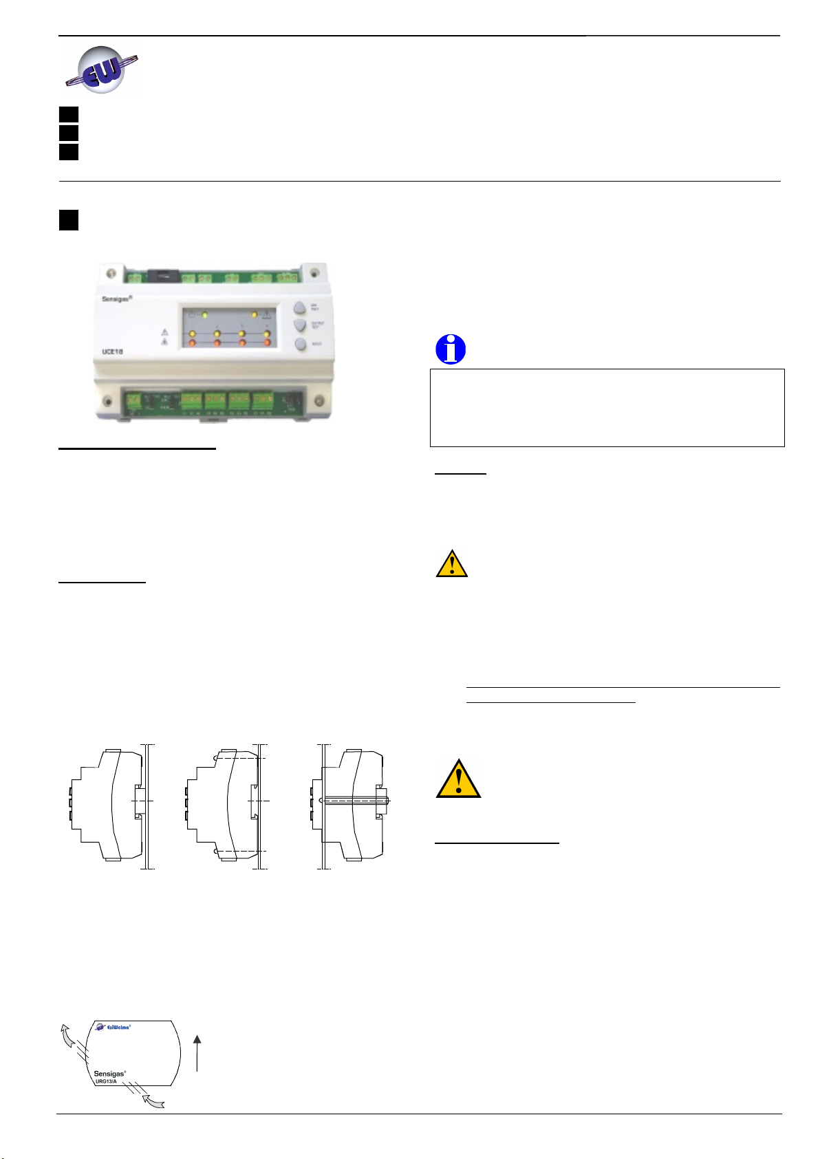
Installation
Mounting position
Check that environmental specifications of the installation place are
compatible with the values listed on Technical Data.
Control Unit UCE18
A on DIN bar (EN50022-35 x 7.5) min length 170mm
B on wall, with 2 screws
C on panel front end using a DIN bar length 195mm,
n°2 50mm spacers, screws and washers
A B C
Sensors UR.13/A
On wall in an area subject to natural air circulation.
Never close to water jets, suction grids, windows, openings,
etc.
At a suitable distance from gas devices in order to avoid
unexpected system actions due to functional losses.
In an accessible position for controls and inspections.
Respect the correct mount orientation
in order to ensure the normal
convection air flow inside the sensor.
URG13/A: High, 20…30cm from the ceiling, to detect light gases
like methane, etc.
URG13.P/A: Low, 20…30cm from the floor, to detect heavy gases
like LPG, propane, butane etc.
URO13/A: At about 1,5m from the floor, to detect carbon
monoxide (CO)
NOTE for sensor installation
In case of a new plant the sensors should be installed as latest as
possible so that typical working-place activities (particularly welding,
painting, etc.) cannot damage the sensors (particularly their sensing
element). In any case the installation must be completed before gas
devices and gas appliances are activated.
Wiring
Common electric cables can be used. However, when installing in
places subject to high electromagnetic interference, use of shielded
cables is recommended.
The UCE18 must be permanently powered at 24VAC.
There is no protection against accidental connection with
230V on the 24V side.
Use double insulation safety transformers; they should be sized for
continuous operation at rated power (refer to Technical Data).
Comply with all current regulations for wiring
Connections must be done in accordance with the diagrams
reported in the following operating instructions
Conform to indicated cable length and cross section
Connect only valves at 12VDC with power not greater than 13W
each (total max 26W) to EV output
Internal relays with positive logic operation that is always
energized contact in case of alarm or fault absence.
Never touch for any reason the sensing element or
electronic circuit. Any tampering might compromise
the correct system operation.
Commissioning
UCE18 does not require any programming or parameterization.
Check that sensors are suitable for the gas type to be detected:
URG13/A = Methane sensor
URG13.P/A = LPG sensor
URO13/A = Carbon Monoxide (CO) sensor
Check that power absorbed by any devices connected to relay
terminals is lower than or equal to contacts maximum ratings
(please refer to Technical Data).
Make certain that termination resistors R=18Kohm 1/4W, factory
supplied, are disconnected from used sensor inputs, while they
must be connected to any unused sensor inputs (terminals C-
S).
If no valve should be connected to EV output, insert a valve
termination Rv 1.8Kohm 1/2W (factory supplied) in the EV ter-
minal. This will avoid any wrong valve fault signal.
s
QAG13/A
METHANE GAS METANO
Pag. 2/4 E191.604_En Rev. 4 dated 30/11/2018 EsiWelma® s.r.l.
Jumper Setup
Set jumper JP2 VALVE TYPE to NC for normally closed valve type
(deliver condition) or to NO for normally open valve type.
Set jumper JP3 VALVE MODE only if normally open valve is used.
CONT position allows to set EV output constantly powered in
case of gas alarm, while PULSE position allows to set it powered
by impulses at 10s intervals.
Jumper for valve
mode selection
Jumper for valve
type selection
VALVE / TYPE
NC NO
VALVE / MODE
CONT. PULSE
NOTE: EACH CHANGE OF JUMPER SETUP MUST BE MADE UNDER POWER OFF.
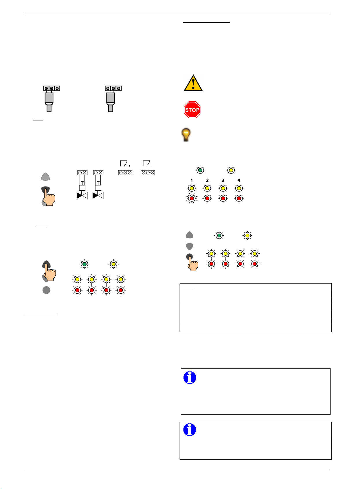
Button functions
OUTPUT TEST button: if pressed for at least 5s, starting from
normal operating condition, temporarily activates all outputs
(valve + relay + hooter) in order to check regular operation of
intervention and signal devices.
LED
TEST
RESET
OUTPUT
TEST
5s
E V C NC NO
M
Relay outputs
de-energized
EV outputs
voltage absence (valve NC)
voltage presence (valve NO)
C NC NO
Alarm Fail
E V
M
Note: relay operation in positive logic
Energized relay = alarm / fault absence
De- energized relay = alarm / fault presence
LED TEST button: temporarily turns all LEDs ON in order to
check their integrity.
LED
TEST
RESET
OUTPUT
TEST
When button is
released the
LEDs go back to
their status
before the button
was pressed
Operation
When the UCE18 is powered at 24VAC preheating phase starts up
(about 1 min) while LEDs will indicate:
Green LED flashing (frequency 1Hz)
Control Unit Yellow LED steady on
Sensor Yellow LEDs steady on
Red LEDs steady on
During this phase there is no voltage at EV terminals, so it is not
possible to energize the solenoid valve(s) if NC type, while it is
possible to energize it/them if NO type. Further, the relays are not
energized.
After preheating phase, the test phase follows (3 min) while it is
possible to check sensors operation. To this purpose, all internal
timings for alarm management are zeroed.
In this phase LEDs will indicate:
Green LED flashing (frequency 2Hz)
Control Unit yellow LED steady on
Sensors Yellow LEDs steady on
Red LEDs steady on
During this phase there is voltage at NC solenoid valve(s), so it is
possible to open it/them using its manual actuator placed on the same
valve. The relays are energized.
Connect the battery to relevant terminals paying attention to polarity.
Operation test
During normal operation it is possible to simulate an alarm, in order to
check system functionality. Act as follows:
Activate test phase (if no more active after preheating) holding
down RESET button for at least 5s.
With cover fitted on approach a gas source to a sensor grid,
and let come out a small amount of gas.
CAUTION: don’t spray the gas directly on the sensor,
otherwise it will be permanently damaged. Act to
increase gradually the gas concentration close to the
sensing element.
Sensors can be permanently damaged when exposed
to high or continuous concentrations of interfering
substances (like fresh paint, ammonia based cleaning
materials, alcoholic or silicone solvents etc).
To check carbon monoxide sensor a combustion smoke can be
used.
After these operation the control unit must indicate a gas alarm status
with these effects:
- Sensor Red LED flashing
- Solenoid valve(s) driven to
closed position
- Changeover of alarm relay
contact (closed contact C -NC)
-
Piezoelectric hooter activated
(if present)
To restore normal operation, once alarm status is over, press RESET.
1 2 3 4
LED
TEST
RESET
OUTPUT
TEST
- Sensor Red LED re-
verts to steady on
- Alarm relay contact
reverts to initial position
(closed contact C - NO)
- Piezoelectric hooter
deactivated (if present)
Note:
An alarm or fault condition during test phase (3 min) causes
flashing of the relevant red or yellow LEDs at 2Hz frequency
instead of 1Hz as indicated in functional table. This latter will be
valid for events starting from normal operating condition.
Return to normal operating condition by pressing RESET button
is possible only if there aren’t any active alarms.
Open the solenoid valve(s) manually.
The control unit continuously checks connections integrity both
for sensors and valves.
The sensor will perform best if used in an area where the
only gas or vapor present, besides fresh air, is the gas or
vapor that you wish to detect.
If used in an area contaminated with relative high concentration
of different interfering substances (like fresh paint, ammonia
based cleaning materials, alcoholic or silicone solvents etc.),
false alarms may occur.
IMPORTANT
We recommend to repeat operating test at least once a year or
after a long stop period and in any case every time that a sensor
is replaced.
EsiWelma® s.r.l. E191.604_En Rev. 4 dated 30/11/2018 Pag. 3/4
Technical Data
Control Unit UCE18
Power supply voltage 24VAC +/- 10%
Frequency 50/60Hz
Power consumption 32VA max (with battery under charge)
Sensor inputs 4 x UR.13/A
Control outputs - 2 Electronic 12VDC (26W max total)
- 2 SPDT Relays 250V 5(3)A
Controlled valve type Normally Closed or
Normally Open
Operation logic positive (normally energized relays,
de-energize in case of alarm / fault)
“VALVE TYPE” Jumper
Valve type NO = Normally Open (type
NC = Normally Closed
“VALVE MODE” Jumper
Valve output mode CONT = continuous
(for NO type only) PULSE = pulses (1 pulse every 10s)
Optical signals (please refer to functional tables)
Green LED Power presence / test
Control U. Yellow LED Valve(s) / control unit fault
Sensors Yellow LEDs Sensor fault
Red LEDs Gas alarm
Sensors connection length
cable 1.5mm2 max 80m
Valve(s) connection length cable 1.5mm2 max 80m
(one cable per valve) cable 1.5mm2 max 40m (2 x 13W)
Battery protection fuse T3.15A 250V 5x20
Dimensions 174 x 106 x 56.5 mm
Protection IP20 – EN60529
Room temperature 0…50°C
Room humidity Max 90% R.H. non condensing
Sensors UR.13/A
Sensing element Tin dioxide semiconductor
Intervention threshold
URG13/A 20% LEL methane (10000ppm)
URG13.P/A 20% LEL LPG (3720ppm)
URO13/A 200 ppm CO
Protection IP44 (if correctly installed)
Average life time
5 years from installation date
Room temperature 0…50°C
Room humidity Max 90% R.H. non condensing
Built-in relay
Operation Positive logic (normally energized).
de-energizes in case of alarm / fault
Changeover contact Voltage free 250V 5(3)A
Built-in battery charger
Charge voltage 13.8VDC
Charge current 0.5A max
Battery 12V 6÷10 Ah (not supplied)
Automatic intervention and current limit
Conformity
Regulations Low Voltage 2014/35/UE
Electromagnetic Compatibility 2014/30/UE
Standards EN50194
EN50270
CAUTION
Lifetime of sensors URG13/A, URG13.P/A e URO13/A is 5
years from installation date. It is necessary to substitute
them systematically before the end of the 5th year of use.
Average lifetime of sensors has been calculated considering a typical
usage in an environment free of pollution substances (gases,
solvents, etc.). A frequent presence or high concentration of these
substances may accelerate normal oxidation process of the sensing
element and consequently shorten its decay time (lifetime).
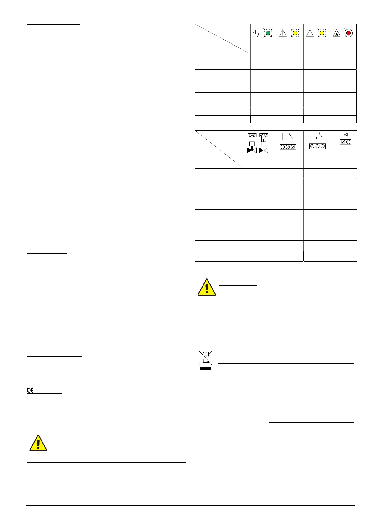
Functional tables
LEDs status
Functions
Green
LED
Control U.
yellow LED
Sensor
yellow LED
Sensor
red LEDs
Sensors preheating (1min) Flash 1Hz ON ON ON
TEST phase (3 min) Flash 2Hz ON ON ON
Normal operation ON ON ON ON
Gas alarm ON ON ON Flash 1Hz*
Valve fault ON Flash 1Hz ON ON
Sensor fault (up to 3) ON ON Flash 1Hz* OFF*
Sensor fault (all) ON OFF Flash 1Hz OFF
Ext. hooter alarm ON Flash 2Hz ON ON
General fault ON OFF OFF OFF
* for relative sensor(s) in alarm/fault
Output status
Functions
2 EV outputs
(NC valve)
Alarm relay
output
Fail relay
output
Hooter
output
Sensors preheat.(1 min) Voltage
absence De-energized De-energized Inactive
TEST phase (3 min) Voltage
presence Energized Energized Inactive
Normal operation Voltage
presence Energized Energized Inactive
Gas alarm Voltage
absence De-energized Energized Active
Valve fault Voltage
absence Energized De-energized Active
Sensor fault (up to 3) Voltage
presence Energized De-energized Active
Sensor fault (all) Voltage
absence De-energized De-energized Active
Ext hooter fault Voltage
presence Energized De-energized Active
General fault Voltage
absence De-energized De-energized Active
Simultaneousness of 2 or more events causes a combined manage-
ment of LEDs and outputs in accordance with a defined priority.
IMPORTANT
IN CASE OF ALARM FOR GAS LEAK OR CARBON
MONOXYDE PRESENCE ACT AS FOLLOWS:
Cut off all free flames and all gas-supplied devices
Do not switch-on or switch-off electrical lights or any other
electrically-supplied appliance, in order to avoid the
sparkling (cause of explosion for explosive gas)
Close the main valve of gas network or of LPG gas bottle
Open windows and doors to ventilate the rooms
Look for the cause of alarm, and eliminate it. If you are not
able to find and to eliminate the cause of the alarm, leave
the building, and, from the outside, call for emergency aids.
Environmental compatibility and disposal
This product was developed and manufactured using materials and
processes which take full account of environmental issues and which
comply with our environmental standards.
Please note the following for disposal at the end of the product life, or
in the event of its replacement:
For disposal, this product is defined as waste from electrical
and electronic equipment (“electronic waste”); do not dispose of
it as household waste. This applies particularly to the PCB
assembly.
Observe all current local laws and regulations.
Always aim for maximum re-use of the basic materials at
minimum environmental stress. Observe any notes on materials
and disposal that may be attached to individual components.
Use local depots and waste management companies, or refer
to your supplier or manufacturer to return used products or to
obtain further information on environmental compatibility and
waste disposal.
The UCE18 shipping case can be recycled. Retain it for future
use or in case of product return to the manufacturer
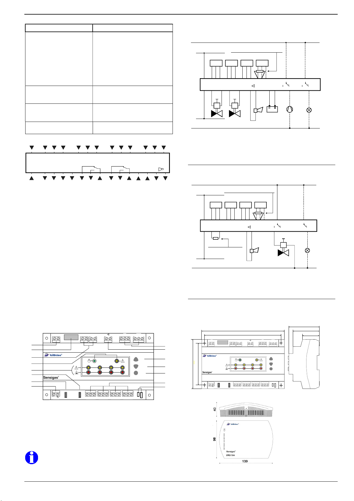
C NC NO C NC NO
+ -
E V
M
E V
M
Pag. 4/4 E191.604_En Rev. 4 dated 30/11/2018 EsiWelma® s.r.l.
Throubleshooting
Effect Possible cause
NC valves type do not open Valve not connected
No power
NO valve type instead of NC type
Incompatible valve type
(power absorption > 26W total)
Alarm not reset or current
Current sensor preheating phase
All sensors defective
General Fault presence
(NO) valve type
does not close
Valve not connected
Sensor not in alarm condition
Cable interrupted
RESET button does not
restore default conditions
A sensor still in alarm condition
Control unit fault
(Control unit Yellow LED OFF)
OUTPUT Test button does
not work
Current fault / alarm
Connections
EV
G
G0
C1 S1 A1
+-
C
NC NO C
NC NO
+-
Batt
C2 S2 A2 C3 S3 A3 C4 S4 A4
EV
ALARM FAIL
G 24 V AC power supply, voltage
G0 24 V AC power supply, system neutral
C1 Sensor input 1 (common)
S1 Sensor input 1 (signal)
A1
Sensor input 1 (power)
C2 Sensor input 2 (common)
S2 Sensor input 2 (signal)
A2
Sensor input 2 (power)
C3 Sensor input 3 (common)
S3 Sensor input 3 (signal)
A3
Sensor input 3 (power)
C4 Sensor input 4 (common)
S4 Sensor input 4 (signal)
A4
Sensor input 4 (power)
E
Valve output 12VDC
V
Valve output 12VDC
C alarm
Alarm relay output (common)
NC alarm
Alarm relay output (normally closed contac
t)
NO alarm
Alarm relay output (normally open contact)
C fail Fault relay output (common)
NC fail Fault relay output (normally closed contact)
NO fail Fault relay output (normally open contact)
+ Batt Battery output +
- Batt Battery output -
+
Hooter output +
-
Hooter output -
Layout
s
LYC18
LED
TEST
RESET
OUTPUT
TEST
1 2 3 4
G G0
24V
C1 S1 A1
E V C NC NO
C2 S2 A2 C3 S3 A3 C4 S4 A4
VALVE / TYPE VALVE / MODE
NC
NO
CONT.
PULSE
+ -
Batt. F1
3A
FAIL
C NC NO
ALARM
E V + -
1
2
7
8
9
10
14
15
11
12
13
3
4
5
6
1
Battery connection terminal 9
Alarm and Fail relay outputs
2
Battery protection fuse T3.15A 10
12VDC 300mA max hooter output
3
12V valve terminals 11
LED Test button
4
Control Unit status LEDs 12
OUTPUT Test button
5
Sensors status LEDs 13
RESET button
6
Valve Mode Jumper
14
Remote sensors terminals
7
Valve Type Jumper
15
Not used
8
24VAC power supply terminal
Due to our policy of continuous product improvement,
specifications are subject to change without notice.
Wiring diagrams
Control unit UCE18 with 4 sensors and n.2 12VDC solenoid valves. 12V buffer
battery and external hooter. Optional devices (lamps, extractors).
Y1
24V AC
G
G0
G
G0 E V
B1
C S A
C1 S1 A1
+-
NO N C
C
M1V1
230V AC
L
N
BATT.
N1
C S A C S A C S A
B2 B3 B4
Y2 L1
N O N C
C
alarm fail
C2 S2 A2C3 S3 A3C4 S4 A4
+-
H1
M
E V
M
R
18Kohm 1/4W termination resistor
to be used in place of sensor
N1 Control unit UCE18
B1 ÷ B4 Sensors UR.13/A
Y1 ÷ Y2 Solenoid valves 12VDC
H1 External hooter 12VDC 300mA max
V1
Battery 12V 6÷10Ah (not supplied)
M1 - L1
Auxiliary devices (lamps, extractors, etc
.).
Control unit UCE18 with con 4 sensors and 230VAC solenoid valve. External
hooter 12V. Control of optional auxiliary devices (signal lamps etc).
Y1
24V AC
G
G0
G
G0 E V
B1
C S A
C1 S1 A1
+-
NO N C
C
230V AC
L
N
BATT.
N1
C S A C S A C S A
B2 B3 B4
L1
N O N C
C
alarm fail
C2 S2 A2C3 S3 A3C4 S4 A4
+-
H1
M
E V
Rv
R
18Kohm 1/4W termination resistor
to be used in place of sensor
1.8Kohm 1/2W termination
resistor to be used in place
of solenoid valve
N1 Control unit UCE18 Rv Factory supplied
B1 ÷ B4 Sensors UR.13/A
Y1 Solenoid valve 230VAC
H1 External hooter 12VDC 300mA max
L1
A
uxiliary devices (signal lamps, etc.).
Dimensions
UCE18
155
106
89
174
56.5
47.9
31
s
LYC18
LED
TEST
RESET
OUTPUT
TEST
1 2 3 4
G G0
24V C1 S1 A1
E V C NC NO
C2 S2 A2 C3 S3 A3 C4 S4 A4
VALVE / TYPE VALVE / MODE
NC
NO
CONT.
PULSE
+ -
Batt. F1
3A
FAIL C NC NO
ALARM
E V + -
UR.13/A
Dimensions in mm
UCE18
UCE18
Popular Control Unit manuals by other brands

Glowworm
Glowworm Smart Wiring Center 2 Installation and servicing

Smith & Nephew
Smith & Nephew 450P Operation & service manual

Heath Zenith
Heath Zenith DUAL BRITE SL-5318 user manual

alphainnoTec
alphainnoTec HMD 1 operating manual

Blackbe;rry
Blackbe;rry ITB100-1 installation guide

InWin
InWin Cobra IW-RS424-07 user manual

red lion
red lion Graphite GMDIO installation guide

Alarmcom
Alarmcom ADC-480Q user guide

Oriental motor
Oriental motor MSS W Series operating manual

seeed studio
seeed studio Grove-125KHz RFID Reader manual

Ublox
Ublox SARA-R4 Series System integration manual

Tripp Lite
Tripp Lite Power Accessory Module PAM-3 instruction sheet


