Eskridge 77 Series Operating instructions

Series 77 Planetary Digger
Service & Repair Manual
EFFECTIVE FOR:
S/N: 17000 - UP
DATE: 08/01/92 - UP
PART NUMBER EXAMPLE: 77BA - 3 2 F 59
SERIES OUTPUT
SHAFT BAIL BOSS MOTOR
NO.
Drive
MOTOR
SUPPLIER
All manuals and user guides at all-guides.com
all-guides.com

SERIES 77 SERVICE MANUAL
SINGLE SPEED
PLANETARY DIGGERDRIVE
This manual will assist in disassembly and assembly of the above series planetary Auger Drive. Item numbers,
indicated in parentheses throughout this manual, refer to the exploded parts breakdown drawing. Individual customer
specifications (bail assembly, output shaft, hydraulic motor, etc. may vary from exploded drawing and standard part
numbers shown. If applicable, refer to individual customer drawing for details.
For any spare or replacement parts, contact your distributor or equipment manufacturer. Always try to have available the
auger unit part number, serial number and date code on the serial tag. This information may be necessary for verification
of any component part numbers. Component part numbers and/or manufacturing lot numbers may be stamped on
individual parts. This information may also be helpful in identifying replacement components.
LUBRICATION AND MAINT NANC
Change the oil after the first 50 hrs. of operation. Oil should be changed at 500 hr. intervals thereafter. Gearboxes in auger
drives require GL-5 grade EP 80/90 gear oil for lubrication. The manufacturer recommends that the unit be partially
disassembled to inspect gears, splines, and bearings at 1000 hour intervals.
OIL CAPACITY: .5 pints
Proper oil level will measure to middle of primary cluster gears when auger drive is in vertical position.
For checking the oil in fully assembled units, see instructions on page 11.
4 Remove the two cap screws (31) and lock washers (40)
from hydraulic motor (50). Remove motor from unit.
Check o-ring (43) for damage.
5 Remove top case (1), input gear (14), and o-ring (44).
6 Lift the primary planet carrier assembly out of the unit
(includes items 7,9,11,17,23, & 33).
7 If sun gear (12) has not been removed from auger drive,
do so now. (Sometimes the sun gear remains in the
primary carrier (7).
8 Remove secondary ring gear (4) and o-ring (44).
9 Remove retaining ring (37) from end of output shaft (49).
10 Lift the secondary planetary assembly out of the unit
(includes items 6,8,10,18,24, & 33). Use a puller if
needed.
11 The unit is now disassembled into groups of parts. The
area(s requiring repair should be identified by thorough
inspection of the parts after they have been cleaned and
dried. Then refer to the appropriate group repair section
below.
CAUTIO : Output shaft is not retained at this point.
1. Primary Planet Carrier subassembly
2. Secondary Planet Carrier subassembly
3. Top case subassembly
4. Base subassembly
UNIT DISASS MBLY
(Refer to exploded view drawing on page 7)
1 Scribe a diagonal line, from the bail assembly (20) to the
bearing carrier (2), across the outside of the auger drive to
assure proper orientation of parts as they are re-as-
sembled.
2 To drain oil, position unit on its side and remove oil plug
(41) located in the top case (1). To help ventilate oil while
draining, loosen hydraulic motor bolts (31). Maximum
drainage occurs when oil is warm.
OTE: Particular care should be taken when placing the
unit in a position for servicing. Unit should be blocked up
so that weight of the unit is resting on the bearing carrier
(2). This fixture must be secure so that the auger drive will
not tip over during disassembly and assembly proce-
dures.
3 Remove the twelve hex head cap screws (29) and hex
flange nuts (34) from bail assembly (20). Lift bail assembly
from unit.
OTE: There are no bolts retaining the major components
together. Proceed with caution when moving the unit.
WAR I G: While working on this
equipment, wear adequate protective
clothing, hearing, eye, and respiratory
protection. Use safe lifting procedures.
2
All manuals and user guides at all-guides.com
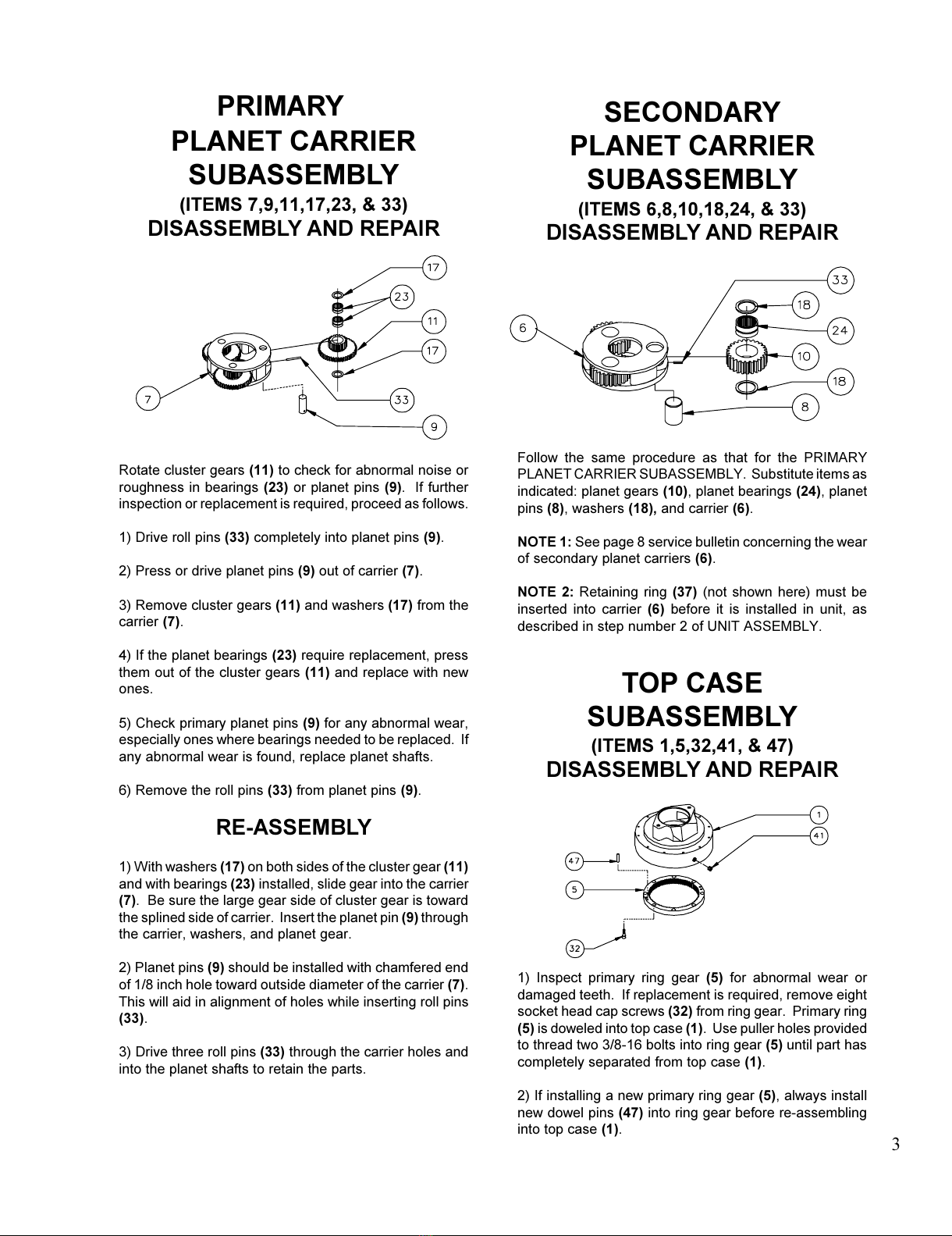
S CONDARY
PLAN T CARRI R
SUBASS MBLY
(ITEMS ,8,10,18,24, & 33)
DISASSEMBLY AND REPAIR
Follow the same procedure as that for the PRIMARY
PLANET CARRIER SUBASSEMBLY. Substitute items as
indicated: planet gears (10), planet bearings (24), planet
pins (8), washers (18), and carrier (6).
OTE 1: See page 8 service bulletin concerning the wear
of secondary planet carriers (6).
OTE 2: Retaining ring (37) (not shown here must be
inserted into carrier (6) before it is installed in unit, as
described in step number 2 of UNIT ASSEMBLY.
TOP CAS
SUBASS MBLY
(ITEMS 1,5,32,41, & 47)
DISASSEMBLY AND REPAIR
1 Inspect primary ring gear (5) for abnormal wear or
damaged teeth. If replacement is required, remove eight
socket head cap screws (32) from ring gear. Primary ring
(5) is doweled into top case (1). Use puller holes provided
to thread two 3/8-16 bolts into ring gear (5) until part has
completely separated from top case (1).
2 If installing a new primary ring gear (5), always install
new dowel pins (47) into ring gear before re-assembling
into top case (1).
PLAN T CARRI R
SUBASS MBLY
(ITEMS 7,9,11,17,23, & 33)
DISASSEMBLY AND REPAIR
Rotate cluster gears (11) to check for abnormal noise or
roughness in bearings (23) or planet pins (9). If further
inspection or replacement is required, proceed as follows.
1 Drive roll pins (33) completely into planet pins (9).
2 Press or drive planet pins (9) out of carrier (7).
3 Remove cluster gears (11) and washers (17) from the
carrier (7).
4 If the planet bearings (23) require replacement, press
them out of the cluster gears (11) and replace with new
ones.
5 Check primary planet pins (9) for any abnormal wear,
especially ones where bearings needed to be replaced. If
any abnormal wear is found, replace planet shafts.
6 Remove the roll pins (33) from planet pins (9).
RE-ASSEMBLY
1 With washers (17) on both sides of the cluster gear (11)
and with bearings (23) installed, slide gear into the carrier
(7). Be sure the large gear side of cluster gear is toward
the splined side of carrier. Insert the planet pin (9) through
the carrier, washers, and planet gear.
2 Planet pins (9) should be installed with chamfered end
of 1/8 inch hole toward outside diameter of the carrier (7).
This will aid in alignment of holes while inserting roll pins
(33).
3 Drive three roll pins (33) through the carrier holes and
into the planet shafts to retain the parts.
PRIMARY
3
All manuals and user guides at all-guides.com

(ITEMS 2,3,21,25,30,4 , & 49)
DISASSEMBLY AND REPAIR
CAUTIO : Output shaft is no longer retained. Care
should be taken not to injure feet because output shaft can
fall out. Care should also be taken not to damage output
shaft when shaft is pressed through base.
1 Output shaft removal. Bearing carrier (2) should be set
pinion side down, as shown, on a plate or table with output
shaft (49) protruding through a hole in table. Press output
shaft out bottom of base by applying a load to top end
(internal end) of shaft until it passes through inner shaft
bearing cone (21).
OTE: If reusing old bearing cone, do not damage roller
cage by pulling on it.
2 If outer bearing cone (25) needs to be replaced a gear
puller may be used.
3 Remove the shaft seal (46) for inspection or replace-
ment. Lubricate inner lip of new shaft seal (46) and slide
the seal onto the shaft (49) until it fits snugly over shaft seal
diameter with the open side toward the inside of the auger
drive.
4 Inspect inner and outer bearing cups (30 & 3) and
replace if necessary.
BASE ASSEMBLY
OTE: Press bearing cone onto output shaft by pressing
on inner race only. DO NOT press on roller cage or it may
damage bearing.
1 If outer bearing cone (25) was removed for replace-
ment, press a new bearing cone (large end down as
shown) onto the shaft until it seats against the shoulder.
2 Place the bearing carrier (2) (output side up, opposite
shown) on the press table.
3 Apply a layer of lithium or general purpose bearing
grease to surface of outer bearing cup (3). Insert the shaft
(49) into the bearing carrier (2) (bearing cone down) and
use a soft hammer to install the shaft seal (46) into the
bearing carrer.
CAUTIO : Output shaft is not retained at this point.
4 Invert this assembly so it is standing on the shaft (on the
press table).
OTE: Press bearing cone onto output shaft by pressing
on inner race only. DO NOT press on roller cage or it may
damage bearing.
5 Apply a layer of lithium or general purpose bearing
grease to surface of inner bearing cup (30). Press the
inner bearing cone (21) (large end up as shown) onto the
shaft (49) until it is seated against inner bearing cup (30).
All subassembly service or repairs should be complete at
this time. Continue on through UNIT ASSEMBLY to
complete unit buildup.
4UNIT
All manuals and user guides at all-guides.com
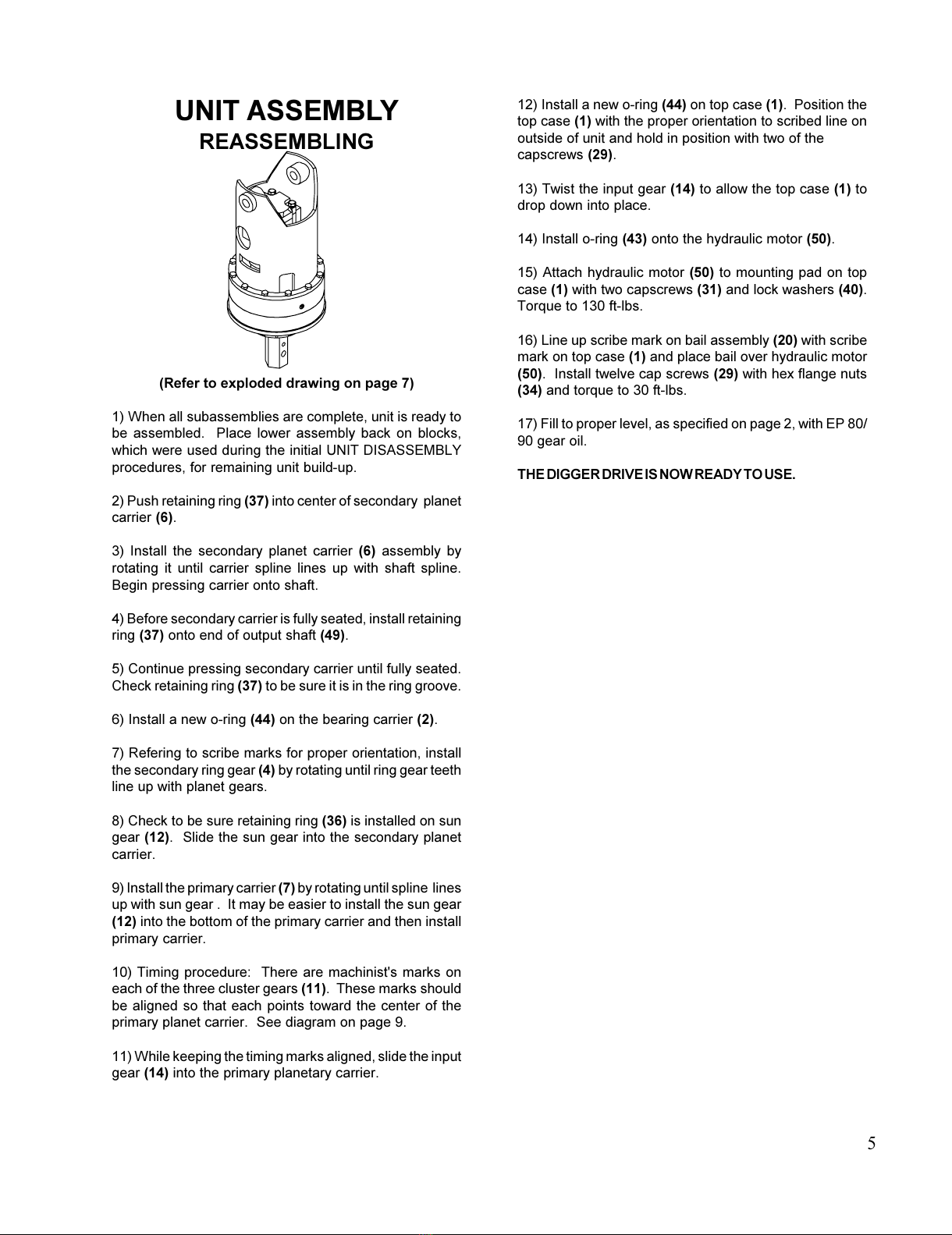
UNIT ASS MBLY
REASSEMBLING
(Refer to exploded drawing on page 7)
1 When all subassemblies are complete, unit is ready to
be assembled. Place lower assembly back on blocks,
which were used during the initial UNIT DISASSEMBLY
procedures, for remaining unit build-up.
2 Push retaining ring (37) into center of secondary planet
carrier (6).
3 Install the secondary planet carrier (6) assembly by
rotating it until carrier spline lines up with shaft spline.
Begin pressing carrier onto shaft.
4 Before secondary carrier is fully seated, install retaining
ring (37) onto end of output shaft (49).
5 Continue pressing secondary carrier until fully seated.
Check retaining ring (37) to be sure it is in the ring groove.
6 Install a new o-ring (44) on the bearing carrier (2).
7 Refering to scribe marks for proper orientation, install
the secondary ring gear (4) by rotating until ring gear teeth
line up with planet gears.
8 Check to be sure retaining ring (36) is installed on sun
gear (12). Slide the sun gear into the secondary planet
carrier.
9 Install the primary carrier (7) by rotating until spline lines
up with sun gear . It may be easier to install the sun gear
(12) into the bottom of the primary carrier and then install
primary carrier.
10 Timing procedure: There are machinist's marks on
each of the three cluster gears (11). These marks should
be aligned so that each points toward the center of the
primary planet carrier. See diagram on page 9.
11 While keeping the timing marks aligned, slide the input
gear (14) into the primary planetary carrier.
12 Install a new o-ring (44) on top case (1). Position the
top case (1) with the proper orientation to scribed line on
outside of unit and hold in position with two of the
capscrews (29).
13 Twist the input gear (14) to allow the top case (1) to
drop down into place.
14 Install o-ring (43) onto the hydraulic motor (50).
15 Attach hydraulic motor (50) to mounting pad on top
case (1) with two capscrews (31) and lock washers (40).
Torque to 130 ft-lbs.
16 Line up scribe mark on bail assembly (20) with scribe
mark on top case (1) and place bail over hydraulic motor
(50). Install twelve cap screws (29) with hex flange nuts
(34) and torque to 30 ft-lbs.
17 Fill to proper level, as specified on page 2, with EP 80/
90 gear oil.
THE DIGGER DRIVE IS OW READY TO USE.
5
All manuals and user guides at all-guides.com
PRODUCT WARRANTY
ESKRIDGE, INC. (Eskridge) warrants to its original pur haser (Customer) that new omponent parts (Parts) sold by Eskridge to the
Customer will be free of defe ts in material and workmanship and will onform to standard spe ifi ations set forth in urrent Eskridge sales
literature or to any ustom spe ifi ations of the Customer a knowledged in writing by Eskridge, SUBJECT TO THE FOLLOWING
QUALIFICATIONS AND LIMITATIONS:
1) Prior to pla ing warranted Parts in servi e, the Customer shall provide proper storage su h that foreign obje ts (e.g.,
rain or debris) annot enter any Parts via entry ports whi h are normally losed during operation.
2) If Parts requiring motorized power for operation are re eived from Eskridge without a motor, do umentation must be
available indi ating proper lubri ation upon pla ement of the Parts in servi e.
3) The Customer must notify Eskridge in writing of any laim for brea h of this warranty promptly after dis overy of a defe t
and in any event prior to the termination of the warranty period, whi h shall ommen e when a unit is pla ed in servi e
and shall expire upon the earlier of (i) the expiration of twelve (12) months from the date of Commen ement of Servi e
(as defined in Paragraph 4) (ii) the ompletion of one thousand (1,000) hours of servi e of the Parts (iii) the expiration
of six (6) months after the expiration of any express warranty relating to the first item of ma hinery or equipment in whi h
the Parts are installed or on whi h it is mounted, or (iv) the installation or mounting of the Parts in or on an item of
ma hinery or equipment other than the first su h item in whi h the Parts are installed or on whi h the Parts are mounted.
4) Parts shall be deemed to have been pla e in servi e (the Commen ement of Servi e) at the time the ma hinery or
equipment manufa tured or assembled by the Customer and in whi h the Parts are installed or on whi h the Parts are
mounted is delivered to the Customers dealer or the original end-user, whi h ever re eives su h ma hinery or equipment
first.
5) This warranty shall not apply with respe t to Parts whi h, upon inspe tion by Eskridge, show signs of disassembly,
rework, modifi ations or improper installation, mounting, use or maintenan e.
6) Eskridge makes no warranty in respe t to hydrauli motors mounted on any Parts. Failure of any su h motor will be
referred to the motor manufa turer.
7) Claims under this warranty will be satisfied only by repair of any defe t(s) or, if repair is determined by Eskridge in its
sole, absolute and un ontrolled dis retion to be impossible or impra ti al, by repla ement of the Parts or any defe tive
omponent thereof. No ash payment or redit will be made for defe tive materials or workmanship. IN NO EVENT
SHALL ESKRIDGE BE LIABLE FOR INCIDENTAL OR CONSEQUENTIAL DAMAGES OF ANY KIND OR
NATURE,WHICH DAMAGES ARE HEREBY EXPRESSLY DISCLAIMED.
8) From time to time, Eskridge may make hanges in the omponent parts manufa tured by it without in orporating
su h hanges in the omponent parts previously shipped. Su h hanges shall not onstitute an admission by
Eskridge of any defe ts or problems with previously manufa tured omponent parts.
9) All freight harges on Parts returned for warranty servi e are the responsibility of the Customer.
THE FOREGOING WARRANTY IS THE SOLE WARRANTY MADE BY ESKRIDGE WITH RESPECT TO ANY PARTS, AND IS
IN LIEU OF ANY AND ALL OTHER WARRANTIES, EXPRESSED OR IMPLIED. THERE ARE NO WARRANTIES WHICH EXTEND
BEYOND THE DESCRIPTION ON THE FACE HEREOF. WITHOUT LIMITING THE GENERALITY OF THE FOREGOING, ESKRIDGE
EXPRESSLY DISCLAIMS ANY IMPLIED WARRANTY OF MERCHANTABILITY OR FITNESS FOR ANY PARTICULAR PURPOSE,
REGARDLESS OF ANY KNOWLEDGE ESKRIDGE MAY HAVE OF ANY PARTICULAR USE OR APPLICATION INTENDED BY THE
PURCHASER. THE SUITABILITY OR FITNESS OF THE PARTS FOR THE CUSTOMERS INTENDED USE, APPLICATION OR
PURPOSE AND THE PROPER METHOD OF INSTALLATION OR MOUNTING MUST BE DETERMINED BY THE CUSTOMER.
WARRANTY RETURN POLICY
1) All Parts shall be returned freight prepaid.
2) Any Parts qualifying for warranty will be repaired with new Parts free of harge (ex ept for freight harges as
provided above).
3) If parts are found to be operable, you have two options:
a. The Parts an be returned to you with a servi e harge for inspe tion, leaning, and routine
repla ement of all rubber omponents and any other parts that show wear; or
b. We an dispose of the Parts at the fa tory if you do not wish it to be returned.
NOTE: Any order of Parts by ustomer shall only be a epted by Eskridge subje t to the terms stated herein. Any pur hase order forms
used by Customer (to a ept this offer to sell) whi h ontain terms ontrary to, different from, or in addition to the terms herein shall be without
effe t, and su h terms shall onstitute material alteration of the offer ontained herein under K.S.A 84-2-207 (2)(b), and shall not be ome
part of the ontra t regarding the sale of the Parts.
6
All manuals and user guides at all-guides.com
all-guides.com

All manuals and user guides at all-guides.com
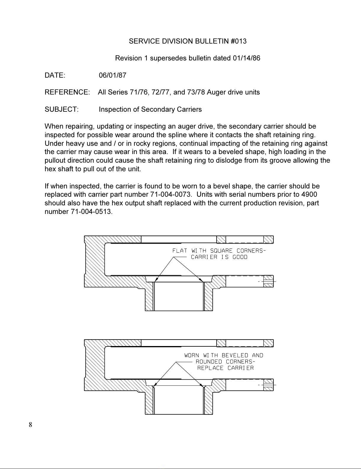
SERVICE DIVISION BULLETIN #013
Revision 1 supersedes bulletin d ted 01/14/86
DATE: 06/01/87
REFERENCE: All Series 71/76, 72/77, nd 73/78 Auger drive units
SUBJECT: Inspection of Second ry C rriers
When rep iring, upd ting or inspecting n uger drive, the second ry c rrier should be
inspected for possible we r round the spline where it cont cts the sh ft ret ining ring.
Under he vy use nd / or in rocky regions, continu l imp cting of the ret ining ring g inst
the c rrier m y c use we r in this re . If it we rs to beveled sh pe, high lo ding in the
pullout direction could c use the sh ft ret ining ring to dislodge from its groove llowing the
hex sh ft to pull out of the unit.
If when inspected, the c rrier is found to be worn to bevel sh pe, the c rrier should be
repl ced with c rrier p rt number 71-004-0073. Units with seri l numbers prior to 4900
should lso h ve the hex output sh ft repl ced with the current production revision, p rt
number 71-004-0513.
8
All manuals and user guides at all-guides.com

Timing diagram:
9
All manuals and user guides at all-guides.com
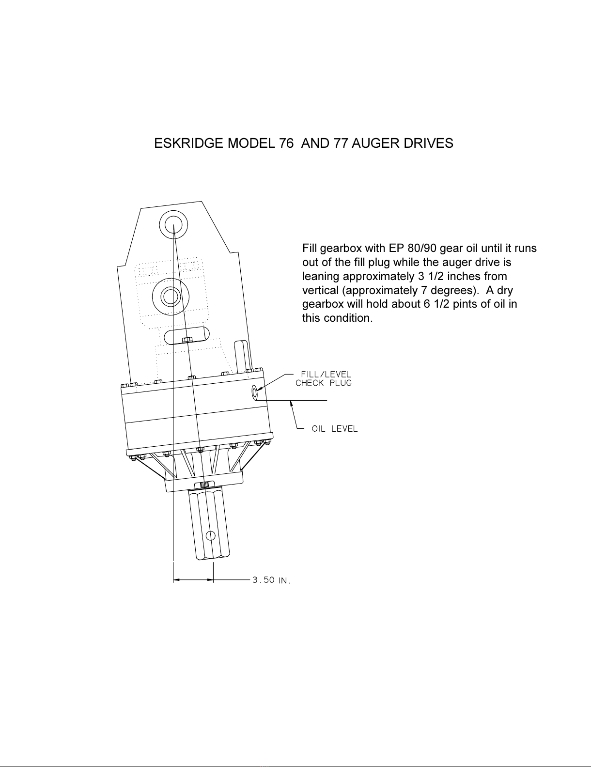
ESKRIDGE MODEL 76 AND 77 AUGER DRIVES
Fill ge rbox with EP 80/90 ge r oil until it runs
out of the fill plug while the uger drive is
le ning pproxim tely 3 1/2 inches from
vertic l ( pproxim tely 7 degrees). A dry
ge rbox will hold bout 6 1/2 pints of oil in
this condition.
All manuals and user guides at all-guides.com
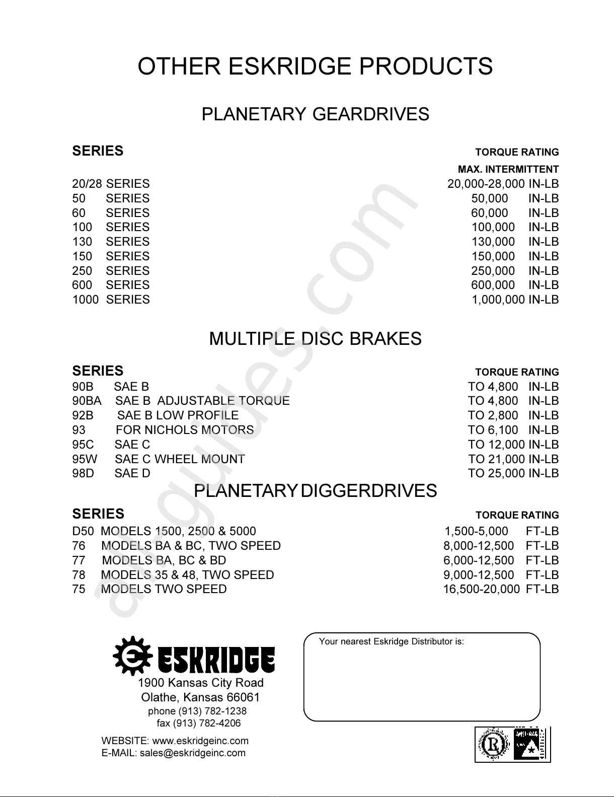
Your nearest Eskridge Distributor is:
1900 K ns s City Ro d
Ol the, K ns s 66061
phone (913) 782-1238
fax (913) 782-4206
WEBSITE: www.es ridgeinc.com
E-MAIL: sales@es ridgeinc.com
OTHER ESKRIDGE PRODUCTS
PLANETARY GEARDRIVES
SERIES TORQUE RATING
MAX. INTERMITTENT
20/28 SERIES 20,000-28,000 IN-LB
50 SERIES 50,000 IN-LB
60 SERIES 60,000 IN-LB
100 SERIES 100,000 IN-LB
130 SERIES 130,000 IN-LB
150 SERIES 150,000 IN-LB
250 SERIES 250,000 IN-LB
600 SERIES 600,000 IN-LB
1000 SERIES 1,000,000 IN-LB
MULTIPLE DISC BRAKES
SERIES TORQUE RATING
90B SAE B TO 4,800 IN-LB
90BA SAE B ADJUSTABLE TORQUE TO 4,800 IN-LB
92B SAE B LOW PROFILE TO 2,800 IN-LB
93 FOR NICHOLS MOTORS TO 6,100 IN-LB
95C SAE C TO 12,000 IN-LB
95W SAE C WHEEL MOUNT TO 21,000 IN-LB
98D SAE D TO 25,000 IN-LB
PLANETARY DIGGERDRIVES
SERIES TORQUE RATING
D50 MODELS 1500, 2500 & 5000 1,500-5,000 FT-LB
76 MODELS BA & BC, TWO SPEED 8,000-12,500 FT-LB
77 MODELS BA, BC & BD 6,000-12,500 FT-LB
78 MODELS 35 & 48, TWO SPEED 9,000-12,500 FT-LB
75 MODELS TWO SPEED 16,500-20,000 FT-LB
All manuals and user guides at all-guides.com
all-guides.com
Other manuals for 77 Series
1
Table of contents
Other Eskridge Construction Equipment manuals


Popular Construction Equipment manuals by other brands


Tesmec
Tesmec AFS404 Installation operation & maintenance

TEREXLIFT
TEREXLIFT Agrilift 625 Operator's handbook

Tate
Tate SmartAire S Guide

JLG
JLG GRADAL 522 Owner's/operator's manual

Doka
Doka Framax stripping corner I Series Original operating instructions

Textron
Textron Greenlee HPB55 Series instruction manual