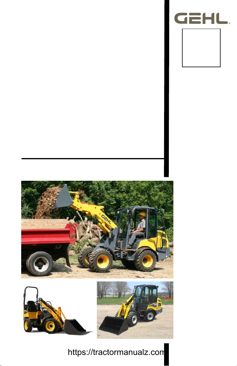
Gehl AL 140 User manual

Operator’s Manual
Form No.
918496
GP0313
English
Revision G
Original
Instructions
–––
Supersedes
918447
AL 140
(SN 11257 and Up)
AL 240(EU)
(SN 21244 and Up)
AL 340
(SN 31365 and Up)
AL 440(EU)
(SN 41250 and Up)
AL 540
(SN 51242 and Up)
Articulated Loaders
https://tractormanualz.com/

GEHL COMPANY
WARRANTY
GEHL COMPANY, hereinafter referred to as Gehl, warrants new Gehl
equipment to the Original Retail Purchaser to be free from defects in
material and workmanship for a period of twelve (12) months from the
Warranty Start Date.
GEHL WARRANTY SERVICE INCLUDES:
Genuine Gehl parts and labor costs required to repair or replace
equipment at the selling dealer’s business location.
GEHL MAKES NO REPRESENTATIONS OR WARRANTIES OF ANY
KIND, EXPRESS OR IMPLIED (INCLUDING THE IMPLIED
WARRANTIES OF MERCHANTABILITY AND FITNESS FOR
PARTICULAR PURPOSE), EXCEPT AS EXPRESSLY STATED IN
THIS WARRANTY STATEMENT.
ANY OF THESE LIMITATIONS EXCLUDED BY LOCAL LAW SHALL
BE DEEMED DELETED FROM THIS WARRANTY; ALL OTHER
TERMS WILL CONTINUE TO APPLY.
SOME STATES DO NOT PERMIT THE EXCLUSION OR LIMITATION
OF THESE WARRANTIES AND YOU MAY HAVE GREATER RIGHTS
UNDER YOUR STATE LAW.
GEHL WARRANTY DOES NOT INCLUDE:
1. Transportation to selling dealer’s business location or, at the option
of the Original Retail Purchaser, the cost of a service call.
2. Used equipment.
3. Components covered by their own non-Gehl warranties, such as
tires, batteries, trade accessories and engines.
4. Normal maintenance service and expendable, high-wear items.
5. Repairs or adjustments caused by: improper use; failure to follow
recommended maintenance procedures; use of unauthorized
attachments; accident or other casualty.
6. Liability for incidental or consequential damages of any type,
including, but not limited to lost profits or expenses of acquiring
replacement equipment.
No agent, employee or representative of Gehl has any authority to bind
Gehl to any warranty except as specifically set forth herein.
204927/AP0407
All-Tach®, Power-A-Tach® and Gehl®are registered trademarks of Manitou Americas, Inc. The products
described in this manual manufactured by Manitou Americas, Inc.
https://tractormanualz.com/

918496/GP0313 1
General Information . . . . . . . . . . . . . . . . . . . . . . . . . . . . . . . . . . 1
Safety Symbol. . . . . . . . . . . . . . . . . . . . . . . . . . . . . . . . . . . . . . . . 1
Contents and Use of this Manual . . . . . . . . . . . . . . . . . . . . . . . . . 1
Ownership Change . . . . . . . . . . . . . . . . . . . . . . . . . . . . . . . . . . . . 2
Manufacturer Information . . . . . . . . . . . . . . . . . . . . . . . . . . . . . . . 2
Machine Designation . . . . . . . . . . . . . . . . . . . . . . . . . . . . . . . . . . 2
Serial Number Plate Location . . . . . . . . . . . . . . . . . . . . . . . . . . . . 3
Loader Information . . . . . . . . . . . . . . . . . . . . . . . . . . . . . . . . . . . . 3
Proper Machine Use . . . . . . . . . . . . . . . . . . . . . . . . . . . . . . . . . . . 4
Using Attachments . . . . . . . . . . . . . . . . . . . . . . . . . . . . . . . . . . . . 4
Component Identification . . . . . . . . . . . . . . . . . . . . . . . . . . . . . . . 5
Service/Dealership Network . . . . . . . . . . . . . . . . . . . . . . . . . . . . . 6
Vibration Information. . . . . . . . . . . . . . . . . . . . . . . . . . . . . . . . . . . 6
Vibration Measurement and Actions . . . . . . . . . . . . . . . . . . . . . 7
Vibration Levels. . . . . . . . . . . . . . . . . . . . . . . . . . . . . . . . . . . . . 7
Safety . . . . . . . . . . . . . . . . . . . . . . . . . . . . . . . . . . . . . . . . . . . . . . 9
2-Post ROPS/FOPS Warning . . . . . . . . . . . . . . . . . . . . . . . . . 10
Mandatory Safety Shutdown Procedure . . . . . . . . . . . . . . . . . . . 10
Before Starting . . . . . . . . . . . . . . . . . . . . . . . . . . . . . . . . . . . . . . 11
During Operation. . . . . . . . . . . . . . . . . . . . . . . . . . . . . . . . . . . . . 12
Provision for Stability/Avoiding Rollover Accidents . . . . . . . . . 15
Electrical Energy . . . . . . . . . . . . . . . . . . . . . . . . . . . . . . . . . . . 16
Service Safety Practices . . . . . . . . . . . . . . . . . . . . . . . . . . . . . . . 16
Battery Hazards. . . . . . . . . . . . . . . . . . . . . . . . . . . . . . . . . . . . 18
Fire Hazards . . . . . . . . . . . . . . . . . . . . . . . . . . . . . . . . . . . . . . . . 19
Crystalline Silica Exposure . . . . . . . . . . . . . . . . . . . . . . . . . . . . . 20
Transporting the Machine . . . . . . . . . . . . . . . . . . . . . . . . . . . . . . 20
Lifting the Machine with a Crane. . . . . . . . . . . . . . . . . . . . . . . . . 20
Hazard and Hazard Avoidance Symbols . . . . . . . . . . . . . . . . . . 21
Safety Decals . . . . . . . . . . . . . . . . . . . . . . . . . . . . . . . . . . . . . . . 22
New Decal Application . . . . . . . . . . . . . . . . . . . . . . . . . . . . . . 22
ANSI-Style and Common Safety Decal Locations . . . . . . . . . 22
ISO-Style Safety Decal Locations . . . . . . . . . . . . . . . . . . . . . . 27
AL 140, AL 240 (EU), AL 340, AL 440 (EU), AL 540
Articulated Loaders Operator’s Manual
TABLE OF CONTENTS
https://tractormanualz.com/

2918496/GP0313
Specifications . . . . . . . . . . . . . . . . . . . . . . . . . . . . . . . . . . . . . . .31
Fluid Capacities/Lubricants. . . . . . . . . . . . . . . . . . . . . . . . . . . .31
Maximum Slopes of Engine Operation . . . . . . . . . . . . . . . . . . .32
SAE (Domestic) Weights and Capacities
AL 500 and AL 300 Series . . . . . . . . . . . . . . . . . . . . . . . . . .33
ISO 6016 (EU) Weights and Capacities
AL 500, AL 400 and AL 300 Series . . . . . . . . . . . . . . . . . . . .34
SAE (Domestic) Weights and Capacities
AL 100 Series . . . . . . . . . . . . . . . . . . . . . . . . . . . . . . . . . . . .35
ISO (EU) Weights and Capacities
AL 100 and AL 200 Series . . . . . . . . . . . . . . . . . . . . . . . . . .36
Engine. . . . . . . . . . . . . . . . . . . . . . . . . . . . . . . . . . . . . . . . . . . .37
Coolant Compound Table. . . . . . . . . . . . . . . . . . . . . . . . . . . . .37
Hydraulics . . . . . . . . . . . . . . . . . . . . . . . . . . . . . . . . . . . . . . . . .38
Electrical System . . . . . . . . . . . . . . . . . . . . . . . . . . . . . . . . . . .38
Sound Levels . . . . . . . . . . . . . . . . . . . . . . . . . . . . . . . . . . . . . .38
Wheels . . . . . . . . . . . . . . . . . . . . . . . . . . . . . . . . . . . . . . . . . . .38
Wheel/Tire Sets . . . . . . . . . . . . . . . . . . . . . . . . . . . . . . . . . . . .39
ROPS and FOPS . . . . . . . . . . . . . . . . . . . . . . . . . . . . . . . . . . .40
Vibration Levels . . . . . . . . . . . . . . . . . . . . . . . . . . . . . . . . . . . .40
AL 500, AL 400 Series Dimensions . . . . . . . . . . . . . . . . . . . . .41
AL 300, AL 200 Series Dimensions . . . . . . . . . . . . . . . . . . . . .43
AL 100 Series Dimensions . . . . . . . . . . . . . . . . . . . . . . . . . . . .45
Standard Features . . . . . . . . . . . . . . . . . . . . . . . . . . . . . . . . . .47
Optional Features . . . . . . . . . . . . . . . . . . . . . . . . . . . . . . . . . . .48
Common Materials and Densities. . . . . . . . . . . . . . . . . . . . . . .49
Operation . . . . . . . . . . . . . . . . . . . . . . . . . . . . . . . . . . . . . . . . . .51
Operating Controls . . . . . . . . . . . . . . . . . . . . . . . . . . . . . . . . . . . .52
Controls and Switches . . . . . . . . . . . . . . . . . . . . . . . . . . . . . . .52
Instrument Panel and Indicators. . . . . . . . . . . . . . . . . . . . . . . .54
Cab Controls (Cab only) . . . . . . . . . . . . . . . . . . . . . . . . . . . . . .56
Cab Environment Controls . . . . . . . . . . . . . . . . . . . . . . . . . . . .56
Air Conditioning Control (option). . . . . . . . . . . . . . . . . . . . . . . .56
Cab Windshield Wiper
Controls . . . . . . . . . . . . . . . . . . . . . . . . . . . . . . . . . . . . . . . . .57
Cab Dome Light . . . . . . . . . . . . . . . . . . . . . . . . . . . . . . . . . . . .57
Cab Defrost. . . . . . . . . . . . . . . . . . . . . . . . . . . . . . . . . . . . . . . .57
Warning Indicators . . . . . . . . . . . . . . . . . . . . . . . . . . . . . . . . . .58
Operator’s Seat Adjustment . . . . . . . . . . . . . . . . . . . . . . . . . . .59
Seat Belt . . . . . . . . . . . . . . . . . . . . . . . . . . . . . . . . . . . . . . . . . .60
Ignition Key Switch . . . . . . . . . . . . . . . . . . . . . . . . . . . . . . . . . .60
https://tractormanualz.com/

918496/GP0313 3
Steering Column Adjustment. . . . . . . . . . . . . . . . . . . . . . . . . . 60
Control Lever. . . . . . . . . . . . . . . . . . . . . . . . . . . . . . . . . . . . . . 61
Hand Throttle. . . . . . . . . . . . . . . . . . . . . . . . . . . . . . . . . . . . . . 61
12V Accessory Power Outlet. . . . . . . . . . . . . . . . . . . . . . . . . . 62
Operation . . . . . . . . . . . . . . . . . . . . . . . . . . . . . . . . . . . . . . . . . . 63
Pre-Operation Checklist . . . . . . . . . . . . . . . . . . . . . . . . . . . . . 63
Extend the ROPS . . . . . . . . . . . . . . . . . . . . . . . . . . . . . . . . . . 64
Restore the ROPS to the raised position . . . . . . . . . . . . . . . . 64
4-Post ROPS Side Gates (Option) . . . . . . . . . . . . . . . . . . . . . 65
Entering and Exiting . . . . . . . . . . . . . . . . . . . . . . . . . . . . . . . . 66
Engine Start. . . . . . . . . . . . . . . . . . . . . . . . . . . . . . . . . . . . . . . 67
Engine Shut Down. . . . . . . . . . . . . . . . . . . . . . . . . . . . . . . . . . 69
Warm-up . . . . . . . . . . . . . . . . . . . . . . . . . . . . . . . . . . . . . . . . . 69
New Machines. . . . . . . . . . . . . . . . . . . . . . . . . . . . . . . . . . . . . 70
Driving on Public Roads . . . . . . . . . . . . . . . . . . . . . . . . . . . . . 70
Lift Arm Down-Stop . . . . . . . . . . . . . . . . . . . . . . . . . . . . . . . . . 74
Travel . . . . . . . . . . . . . . . . . . . . . . . . . . . . . . . . . . . . . . . . . . . 74
Slow/Fast Travel Speed Mode Selection . . . . . . . . . . . . . . . . 76
Differential Lock Operation . . . . . . . . . . . . . . . . . . . . . . . . . . . 76
Load Handling . . . . . . . . . . . . . . . . . . . . . . . . . . . . . . . . . . . . . 77
Parking the Loader . . . . . . . . . . . . . . . . . . . . . . . . . . . . . . . . . 77
Multi-purpose Joystick. . . . . . . . . . . . . . . . . . . . . . . . . . . . . . . 78
AL 100, AL 200(EU), AL 300, AL 400(EU) Self-Leveling
Feature. . . . . . . . . . . . . . . . . . . . . . . . . . . . . . . . . . . . . . . . . 79
AL 500 Series Limited Self-Leveling . . . . . . . . . . . . . . . . . . . . 79
Float Positions. . . . . . . . . . . . . . . . . . . . . . . . . . . . . . . . . . . . . 80
Attachments . . . . . . . . . . . . . . . . . . . . . . . . . . . . . . . . . . . . . . . . 81
General Instructions . . . . . . . . . . . . . . . . . . . . . . . . . . . . . . . . 81
Connect/Disconnect Attachments . . . . . . . . . . . . . . . . . . . . . . 81
All-Tach® System Hitch Connection . . . . . . . . . . . . . . . . . . . . 81
All-Tach® System Hitch Disconnection. . . . . . . . . . . . . . . . . . 82
Hydraulic Power-A-Tach® System Hitch Connection . . . . . . . 83
Hydraulic Power-A-Tach® System Hitch Disconnection. . . . . 85
Auxiliary Hydraulics. . . . . . . . . . . . . . . . . . . . . . . . . . . . . . . . . 86
Auxiliary Circuit Pressure Relief . . . . . . . . . . . . . . . . . . . . . . . 86
Auxiliary Hydraulics Connections . . . . . . . . . . . . . . . . . . . . . . 88
Auxiliary Hydraulics Control Buttons . . . . . . . . . . . . . . . . . . . . 89
Operating Attachments . . . . . . . . . . . . . . . . . . . . . . . . . . . . . . 92
Bucket . . . . . . . . . . . . . . . . . . . . . . . . . . . . . . . . . . . . . . . . . . . 92
Loading Loose Material. . . . . . . . . . . . . . . . . . . . . . . . . . . . . . 92
Scraping Soft Material. . . . . . . . . . . . . . . . . . . . . . . . . . . . . . . 92
https://tractormanualz.com/

4918496/GP0313
Scraping Hard Material. . . . . . . . . . . . . . . . . . . . . . . . . . . . . . .93
Towing the Loader . . . . . . . . . . . . . . . . . . . . . . . . . . . . . . . . . . . .94
Precautions. . . . . . . . . . . . . . . . . . . . . . . . . . . . . . . . . . . . . . . .94
Towing AL 100 Series Machines . . . . . . . . . . . . . . . . . . . . . . .94
Preparation . . . . . . . . . . . . . . . . . . . . . . . . . . . . . . . . . . . . . . . .94
Towing AL 300 Series Machines . . . . . . . . . . . . . . . . . . . . . . .95
Preparation . . . . . . . . . . . . . . . . . . . . . . . . . . . . . . . . . . . . . . . .95
Towing AL 500 and AL 400 Series Machines. . . . . . . . . . . . . .95
Preparation . . . . . . . . . . . . . . . . . . . . . . . . . . . . . . . . . . . . . . . .95
Towing Procedure. . . . . . . . . . . . . . . . . . . . . . . . . . . . . . . . . . .96
After Towing . . . . . . . . . . . . . . . . . . . . . . . . . . . . . . . . . . . . . . .96
Loading and Transporting . . . . . . . . . . . . . . . . . . . . . . . . . . . . . .97
Crane Lifting . . . . . . . . . . . . . . . . . . . . . . . . . . . . . . . . . . . . . . .99
Maintenance . . . . . . . . . . . . . . . . . . . . . . . . . . . . . . . . . . . . . . .103
Maintenance Schedule. . . . . . . . . . . . . . . . . . . . . . . . . . . . . . . .104
Check, Clean and Inspect. . . . . . . . . . . . . . . . . . . . . . . . . . . .104
Leakage Check. . . . . . . . . . . . . . . . . . . . . . . . . . . . . . . . . . . .105
Lubrication and Filter Changes. . . . . . . . . . . . . . . . . . . . . . . .106
Functional Check . . . . . . . . . . . . . . . . . . . . . . . . . . . . . . . . . .106
Dealer Service . . . . . . . . . . . . . . . . . . . . . . . . . . . . . . . . . . . . . .107
Tilting the Platform . . . . . . . . . . . . . . . . . . . . . . . . . . . . . . . . . . .107
Tilting Up the Platform . . . . . . . . . . . . . . . . . . . . . . . . . . . . . .107
Tilting the Platform Down . . . . . . . . . . . . . . . . . . . . . . . . . . . .108
Engine Maintenance. . . . . . . . . . . . . . . . . . . . . . . . . . . . . . . . . .109
Engine Oil . . . . . . . . . . . . . . . . . . . . . . . . . . . . . . . . . . . . . . . .109
Checking Engine Oil Level . . . . . . . . . . . . . . . . . . . . . . . . . . .109
Changing Engine Oil and Filter. . . . . . . . . . . . . . . . . . . . . . . .110
Air Cleaner . . . . . . . . . . . . . . . . . . . . . . . . . . . . . . . . . . . . . . .112
Accessing the Outer and Inner Filter Elements . . . . . . . . . . .113
Changing the Filter Elements . . . . . . . . . . . . . . . . . . . . . . . . .113
Engine Cooling System . . . . . . . . . . . . . . . . . . . . . . . . . . . . .114
Checking Coolant Level . . . . . . . . . . . . . . . . . . . . . . . . . . . . .114
Cleaning Cooling System . . . . . . . . . . . . . . . . . . . . . . . . . . . .114
Draining/Refilling Cooling System . . . . . . . . . . . . . . . . . . . . .115
Fuel System . . . . . . . . . . . . . . . . . . . . . . . . . . . . . . . . . . . . . .116
Adding Fuel. . . . . . . . . . . . . . . . . . . . . . . . . . . . . . . . . . . . . . .116
Changing Fuel Filter . . . . . . . . . . . . . . . . . . . . . . . . . . . . . . . .116
Water Separator Maintenance . . . . . . . . . . . . . . . . . . . . . . . .117
Checking and Adjusting V-belt Tension . . . . . . . . . . . . . . . . .119
Air Conditioning V-Belt . . . . . . . . . . . . . . . . . . . . . . . . . . . . . .119
Air Conditioning Maintenance. . . . . . . . . . . . . . . . . . . . . . . . .120
https://tractormanualz.com/

918496/GP0313 5
Filter Replacement . . . . . . . . . . . . . . . . . . . . . . . . . . . . . . . . 120
Windshield Washer Reservoir (Cab Only). . . . . . . . . . . . . . . 121
Hydraulic System Maintenance . . . . . . . . . . . . . . . . . . . . . . . . 122
Hydraulic Oil . . . . . . . . . . . . . . . . . . . . . . . . . . . . . . . . . . . . . 122
Checking Hydraulic Oil Level . . . . . . . . . . . . . . . . . . . . . . . . 122
Changing Hydraulic Oil and Filter . . . . . . . . . . . . . . . . . . . . . 123
Hydraulic Hose Maintenance . . . . . . . . . . . . . . . . . . . . . . . . . . 124
Planetary Axles . . . . . . . . . . . . . . . . . . . . . . . . . . . . . . . . . . . . . 125
Changing Planetary Axle Oil . . . . . . . . . . . . . . . . . . . . . . . . . 125
Changing Axle Wheel-Hub Oil (AL 500, AL 400 and
AL 300 Series). . . . . . . . . . . . . . . . . . . . . . . . . . . . . . . . . . . 125
Changing Axle Center Oil (AL 500, AL 400 and
AL 300 Series). . . . . . . . . . . . . . . . . . . . . . . . . . . . . . . . . . . 126
Changing Axle Oil (AL 200 and AL 100 Series) . . . . . . . . . . 127
Brake Fluid Reservoir (AL 300, AL 400 and AL 500 Series). . . 128
Checking Brake Fluid Reservoir Level . . . . . . . . . . . . . . . . . 128
Wheels and Tires . . . . . . . . . . . . . . . . . . . . . . . . . . . . . . . . . . . 128
Wheel Fasteners . . . . . . . . . . . . . . . . . . . . . . . . . . . . . . . . . . 128
Tires . . . . . . . . . . . . . . . . . . . . . . . . . . . . . . . . . . . . . . . . . . . 129
Tire Rotation . . . . . . . . . . . . . . . . . . . . . . . . . . . . . . . . . . . . . 129
Checking Tire Pressure. . . . . . . . . . . . . . . . . . . . . . . . . . . . . 129
Liquid Tire Ballast (AL 500 Series) . . . . . . . . . . . . . . . . . . . . 129
Lubrication . . . . . . . . . . . . . . . . . . . . . . . . . . . . . . . . . . . . . . . . 130
Electrical System . . . . . . . . . . . . . . . . . . . . . . . . . . . . . . . . . . . 134
Fuses. . . . . . . . . . . . . . . . . . . . . . . . . . . . . . . . . . . . . . . . . . . 134
Steering Column Fuses – AL 500/400/300 Series;
AL 100 (EU), AL 200 Optional. . . . . . . . . . . . . . . . . . . . . . . 135
Steering Column Fuses – AL 100 Series and AL 200
Standard . . . . . . . . . . . . . . . . . . . . . . . . . . . . . . . . . . . . . . . 136
Cab and In-Line Fuses . . . . . . . . . . . . . . . . . . . . . . . . . . . . . 137
Control Modules . . . . . . . . . . . . . . . . . . . . . . . . . . . . . . . . . . 139
Machine Control Module . . . . . . . . . . . . . . . . . . . . . . . . . . . . 139
Drive Control Module (AL 500/400 Series) . . . . . . . . . . . . . . 139
Drive Control Module Error Codes . . . . . . . . . . . . . . . . . . . . 140
Battery . . . . . . . . . . . . . . . . . . . . . . . . . . . . . . . . . . . . . . . . . . 141
Using a Booster Battery (Jump-Starting). . . . . . . . . . . . . . . . 142
Remote Battery Terminal . . . . . . . . . . . . . . . . . . . . . . . . . . . 143
Storing the Loader . . . . . . . . . . . . . . . . . . . . . . . . . . . . . . . . . . 144
Before Storage . . . . . . . . . . . . . . . . . . . . . . . . . . . . . . . . . . . 144
After Storage . . . . . . . . . . . . . . . . . . . . . . . . . . . . . . . . . . . . . 144
Final Shutdown / Decommissioning . . . . . . . . . . . . . . . . . . . . . 145
https://tractormanualz.com/

6918496/GP0313
Before Disposal . . . . . . . . . . . . . . . . . . . . . . . . . . . . . . . . . . .145
Machine Disposal . . . . . . . . . . . . . . . . . . . . . . . . . . . . . . . . . .146
Maintenance Log . . . . . . . . . . . . . . . . . . . . . . . . . . . . . . . . . . . .147
Troubleshooting . . . . . . . . . . . . . . . . . . . . . . . . . . . . . . . . . . . .153
Index . . . . . . . . . . . . . . . . . . . . . . . . . . . . . . . . . . . . . . . . . . . . .165
Torque Specifications. . . . . . . . . . . . . . . . . . . . . . . . . . . . . . . . .169
EC Declaration of Conformity . . . . . . . . . . . . . . . . . . . . . . . . . . .171
https://tractormanualz.com/

918496/GP0313 1
CHAPTER 1
GENERAL INFORMATION
Safety Symbol
Manitou Americas, in cooperation with the Society of Auto-
motive Engineers, as adopted this safety alert symbol. This
symbol identifies potential safety hazards, which, if not
properly avoided, could result in injury. When you see this symbol in
this manual or on the machine, your are reminded to BE ALERT!
Your personal safety is involved!
Contents and Use of this Manual
This operator’s manual provides detailed operating procedures for safe, effective
and proper machine use. Safe operation is detailed in the Safety chapter of this
manual, beginning on page 9. Specification, maintenance and troubleshooting
information is also included in this manual.
Improper operation, inspection and maintenance of the machine can result in
injury or death. Read and understand the contents of this manual completely and
become familiar with the machine before operation. Contact your authorized
dealer with any questions about information in this manual, if extra manuals are
required, or about availability of manuals in other languages.
Throughout this manual, information is provided set in or italic type and
introduced by the words Notice or Important. Carefully read and follow these
messages to improve operating and maintenance efficiency, to avoid breakdowns
and damage, and extend the life of the machine.
Note: Because of ongoing product improvements, illustrations and listings in this
manual may not exactly match the machine. Manitou Americas reserves the right
to modify and improve products at any time without notice.
A storage box (A, Fig. 1) behind the seat
is provided for manual storage. Store the
operator’s manual in this box at all times.
Note: AL500 Series machines with air
conditioning use a cylindrical manual
storage container located next to the
operator’s seat.
This manual is considered a permanent
part of the machine and should be with
the machine at all times. Replace this
manual promptly if it becomes damaged,
lost, or stolen.
Figure 1 – Manual Storage
Location (except AL500 Series
with air conditioning)
A
https://tractormanualz.com/

2918496/GP0313
Ownership Change
If the machine is resold, include this operator’s manual as part of the sale.
If the machine was purchased “used,” or if the owner’s address has changed,
please provide your dealer or Manitou Americas Service Department with the
owner’s name and current address, along with the machine model and serial
numbers. This will allow the registered owner information to be updated, so that
the owner can be notified directly in case of an important product issue, such as a
safety update program.
Manufacturer Information
Products described in this manual manufactured by Manitou Americas, Inc.
Machine Designation
Earth-Moving Machinery/Loaders/Compact/Seated Operator
https://tractormanualz.com/

918496/GP0313 3
Serial Number Plate Location
The serial number placard is located on the front frame on the right side of the
machine (B, Fig. 2).
Additionally, the following components also have identification placards:
•Engine
• Hydraulic pump
• Hydraulic drive motor(s)
•Axles
Loader Information
Use the spaces provided below to record purchase location and date, model and
serial number information.
Purchased from
Date of Purchase
Loader Model Number
Loader Serial Number
Engine Serial Number
Hydraulic Pump Identification Number
Drive Motor Identification Number(s)
Axle Identification Number
Figure 2 – Serial
Number Plate
Earth-Moving Machinery/Loaders/Compact/Seated Operator
Product
Identification
Number Series
Net power kW
kg
kg
kg
km/h
hp
lbs.
lbs.
lbs.
mph
Operating mass
Max axle load-front
Max axle load-rear
Max speed
Year of Construction
Manufactured by Manitou Americas, Inc.
One Gehl Way
West Bend, WI 53095-0179 USA
B
https://tractormanualz.com/

4918496/GP0313
Proper Machine Use
Improper use of the machine can result in
property damage, injury or death.
The machine is designed only for digging, picking up, lifting, transporting and
unloading materials. Use with approved attachments is also allowed. Use in any
other way is considered as contrary to the intended use. Compliance with, and
strict adherence to, the conditions of operation, service and repair, as specified by
the manufacturer, also constitute essential elements of the intended use.
The machine was designed and built according to the best available technology
and approved safety regulations in the countries where it is sold. However, it is
impossible to completely safeguard against abusive and/or improper use. The
operator must always consider potential safety risks and hazards during
operation. Accident prevention regulations, all other generally recognized
regulations on safety and occupational medicine, and all road traffic regulations,
must be observed at all times.
The machine must be maintained in proper operating condition. Any damaged or
malfunctioning parts must be repaired or replaced immediately.
Any arbitrary modifications carried out to the machine may relieve the
manufacturer of liability for any resulting damage or injury.
Using Attachments
Read all documentation provided with attachments to learn how to safely operate
and maintain them.
Do not use the machine for any applications or purposes other than those
described in this manual or manuals supplied with attachments. Contact the
Manitou Americas Service Department before using attachments or equipment
not approved by Manitou Americas, or if there are any questions about approved
attachments. Use of non-approved attachments or unauthorized modifications is
prohibited.
WARNING
https://tractormanualz.com/

918496/GP0313 5
Component Identification
Figure 3 – Component Identification (AL 500 Series Model Shown)
13
2
4
5
69
8
10
7
1. Engine cover
2. Multi-purpose joystick
3. Steering column
4. Road lights (4 locations)
5. Lift arm
6. Speed control pedal (brake/inch pedal
on left side)
7. Manual storage box
8. Parking brake (left side)
9. Fuel filler neck
10. All-Tach®system bracket levers (2
locations)
https://tractormanualz.com/

6918496/GP0313
Service/Dealership Network
Your dealership network stands ready to provide any assistance that may be
required, including providing genuine service parts. All service parts should be
obtained from your dealer. Provide complete information about the part and
include the machine model and serial numbers. Record these numbers in the
spaces provided in “Loader Information” on page 3. Refer to the parts manual for
a complete listing of service parts.
Manitou Americas strives to continuously improve its products and reserves the
right to make changes and improvements in the design and construction of any
part without incurring the obligation to install such changes on any previously
delivered machine.
Vibration Information
Compact construction equipment is generally used in harsh environments. This
type of usage can expose an operator to uncomfortable levels of vibration. It is
useful to understand exposure to vibration levels when operating compact
equipment and what can be done to reduce vibration exposure. As a result,
equipment operation can be more efficient, productive and safe.
An operator’s exposure to vibration occurs in two ways:
• Whole-Body Vibration (WBV)
• Hand-Arm Vibration (HAV)
WBV issues are primarily addressed in this manual, because evaluations have
shown that operation of mobile compact construction equipment on work sites
typically results in HAV levels less than the allowed exposure limit of 2.5 m/s2.
Member States of the European Union must comply with the Physical Agents
(vibration) Directive, 2002/44/EC.
Effective control of vibration exposure for an operator involves more than just
vibration levels on the machine. The work site, how the machine is used, and
proper training all play important roles in reducing vibration exposure.
Vibration exposure results from:
• Work site conditions.
• How the machine is operated.
• The machine characteristics.
Common causes of high WBV levels:
• Using a machine that is improper for the task.
• Work site with potholes, ruts and debris.
• Improper operating techniques, such as driving too fast.
• Incorrect adjustment of the seat and controls.
• Other physical activities while using the machine.
https://tractormanualz.com/

918496/GP0313 7
Vibration Measurement and Actions
The vibration directive places the responsibility for compliance on employers.
Actions that should be followed by employers include:
• Assess the levels of vibration exposure.
• Determine from this assessment if operators will be exposed to vibration
levels above the limits stated in the directive.
• Take appropriate actions to reduce operator’s exposure to vibration.
• Provide operators with information and training to reduce their exposure
to vibration.
• Keep good records and update operations and training on a regular basis.
If the assessment concludes that vibration level exposure is too high, one or more
of the following actions may be necessary:
1. Train operators
• Perform operations (accelerating, steering, braking, etc.) in a smooth
manner.
• Adjust the controls, mirrors and seat suspension for comfortable
operation.
• Travel across the smoothest parts of the work site and avoid ruts and
potholes.
2. Choose proper equipment for the job
• Use machines with the proper power and capacity.
• Select machines with good suspension seats.
• Look for controls that are easy to use.
• Ensure good visibility from the operator’s position.
3. Maintain the work site
• Smooth ruts and fill potholes in traffic areas whenever possible.
• Clean up debris frequently.
• Vary traffic patterns to avoid exposure to rough terrain.
4. Maintain the equipment
• Ensure correct tire pressures.
• Check that seat suspension and all controls work smoothly and properly.
Vibration Levels
The table lists typical whole-body vibration levels for the machine. See
“Vibration Levels” on page 40.
https://tractormanualz.com/

8918496/GP0313
Notes
https://tractormanualz.com/

918496/GP0313 9
CHAPTER 2
SAFETY
This manual and decals on the machine warn of safety hazards and should be
read and observed closely.
Before operating the machine, first read and study the safety information in this
manual. Additionally, anyone who operates or works on the machine must be
familiar with these safety precautions.
This safety alert symbol means ATTENTION! ALWAYS BE
ALERT! YOUR SAFETY IS INVOLVED! This symbol is used
throughout this operator’s manual and on the decals on the
machine.
“DANGER” indicates an imminently hazardous
situation, which, if not avoided, will result in
death or serious injury.
“WARNING” indicates a potentially hazardous
situation, which, if not avoided, could result in
death or serious injury.
“CAUTION” indicates a potentially hazardous
situation, which, if not avoided, may result in
minor injury or property damage. It is also used to alert users of
unsafe practices.
It is essential that operators are thoroughly trained in the safe operation of the
machine and handling loads. Operators must not be physically or mentally
impaired. Do not allow minors or unqualified personnel to operate the machine,
or to be near the machine unless they are properly supervised. It is recommended
that the operator be capable of obtaining a valid motor vehicle operator’s license.
Use of this machine is subject to certain hazards that cannot be eliminated by
mechanical means, but only by exercising intelligence, care and common sense.
Such hazards include: hillside operation, overloading, load instability, poor
maintenance, and using the machine for a purpose for which it was not intended
or designed.
Manitou Americas always takes operator’s safety into consideration during the
design process. Guards and shields are provided, which protect the operator and
bystanders from moving parts and other hazards. Operators must be alert,
however, because some areas cannot be guarded or shielded without preventing
or interfering with proper operation.
Different applications may require optional safety equipment. Be sure you know
the work site hazards and equip the machine and the operator as necessary. The
information in this manual does not replace any applicable safety rules and laws.
Before operating the machine, learn the rules and laws for your area. Make sure
the machine is equipped as required according to these rules/laws.
DANGER
WARNING
CAUTION
https://tractormanualz.com/

10 918496/GP0313
Remember that some risks to our health may not be immediately apparent.
Exhaust gases and noise pollution may not be visible, but these hazards can cause
permanent injuries.
Some photographs in this manual may show doors, guards and shields open or
removed for the purposes of illustration only. Be sure that all doors, guards and
shields are in the proper operating positions before starting the engine to operate
the machine.
2-Post ROPS/FOPS Warning
The machine MUST be equipped with a Falling-
Object Protective Structure (FOPS) when the
machine is intended for use in applications where there is a risk of
falling objects.
Machines equipped with two-post ROPS MUST NOT be used where
there is a risk of falling objects. A risk of falling objects existing
whenever a load is lifted above the operator’s head. A two-post
ROPS does NOT protect against falling objects. A four-post FOPS
MUST be installed on machines used where there is a risk of falling
objects.
Mandatory Safety Shutdown Procedure
BEFORE cleaning, adjusting, lubricating, fueling, or servicing the machine, or
leaving it unattended:
1. Bring the machine to a complete stop on a level surface. Avoid parking on an
incline or hillside, but if this is not possible, park across the slope and block
the tires.
2. Be sure all working equipment and/or attachments are stopped and the auxil-
iary valve is in neutral.
3. Lower the lift arm and attachment completely.
4. Place forward/reverse drive switch (on top of the joystick) into the neutral
position.
5. Apply the parking brake.
6. Move the throttle to low idle position and shut off the engine.
7. Wait for all movement to stop. Turn the ignition key to the “I” or RUN posi-
tion and move the multi-purpose joystick in all directions to verify that the
hydraulic system is de-pressurized.
8. If so equipped, press the auxiliary hydraulics pressure relief control. After
pressing, make sure this control returns to the neutral position.
9. Turn off the ignition.
10. Unfasten the seat belt and remove the ignition key and take it with you. Exit
the machine using the hand holds.
ONLY when these precautions have been taken can you be sure it is safe to
proceed. Failure to follow this procedure could result in death or serious injury.
WARNING
https://tractormanualz.com/

918496/GP0313 11
Before Starting
• Do not remove or modify the Roll-Over Protective Structure (“ROPS”)
unless instructed to do so in approved installation instructions.
Modifications, such as welding, drilling or cutting, can weaken the
structure and reduce the protection it provides. A damaged ROPS cannot
be repaired – it must be replaced.
• Never operate the machine without a ROPS or FOPS installed.
• To ensure safe operation, replace damaged or worn-out parts with genuine
service parts.
• The machine is designed and intended to be used only with approved
attachments. To avoid possible personal injury, equipment damage and
performance problems, use only attachments that are approved for use on
and within the operating capacity of the machine (see weights and
capacity information, starting on page 33). Contact the Manitou Americas
service department for information on attachment approval and
compatibility with specific machine models. Manitou Americas cannot be
responsible if the machine is used with a non-approved attachment.
• Remove all trash and debris from the machine every day, especially in the
engine compartment, to minimize the risk of fire.
• Always face the machine and use the hand holds and steps when entering
and exiting the machine. Do not jump off the machine. See “Entering and
Exiting” on page 66.
• Never use starting aids. Engine pre-heating is used for cold weather
starting. Engine pre-heating can cause either or other starting fluid to
detonate, causing injury or damage.
• Walk around the machine and inspect it before using it. Look for damage,
loose or missing parts, leaks, etc.
• Warn all nearby personnel before starting the machine.
• Check for proper tire pressure in all four tires before operating the
machine and add air if necessary. Improperly pressurized tires adversely
affect machine stability. Regularly check wheel fasteners for tightness.
See “Wheel Fastener Torque” on page 38.
• Contact the proper local authorities for utility line locations BEFORE
starting to dig. In North America, contact the North American One-Call
Referral System at 8-1-1 in the U.S., or 1-888-258-0808 in the U.S. and
Canada.
• Below-ground hazards also include water mains, tunnels and buried
foundations. Know what is underneath the work site before starting to dig.
• Before working near power lines (either above-ground or buried cable-
type), always contact the power utility and establish a safety plan with
them.
• If temperatures are changing, be cautious of dark and wet patches when
working or traveling over frozen ground. Stay away from ditches,
overhangs and other weak support surfaces.
https://tractormanualz.com/

12 918496/GP0313
• The operator’s area, steps and hand holds must be free of oil, dirt, ice and
unsecured objects.
• If a lighting system is installed, check its operation before working in
darkness.
• Always keep lights, mirrors and windows clean. Poor visibility can cause
accidents.
• NEVER start the engine if there is any indication that maintenance or
service work is in progress, or if a warning tag is attached to the controls.
• Replace damaged safety decals and a lost or damaged operator’s manual.
• Terrain and soil conditions at the work site, approaching traffic, weather-
related hazards and any above-or below-ground obstacles and hazards
should be observed and monitored by all work crew members.
• Adjust the seat to allow full actuation of all controls. Never adjust the seat
during machine operation.
• Read the operator’s manual provided with each attachment used with the
machine before starting the engine.
• Before working on or with the machine, remove jewelry, tie back long
hair, and do not war loose-fitting garments, such as, scarves, ties,
unzipped jackets, etc., which could become caught in the moving parts of
the machine and cause injury.
During Operation
• ALWAYS fasten the seat belt securely and properly. Never operate the
machine without the seat belt fastened around the operator.
• Check indicators and displays for normal conditions after starting the
engine. Listen for unusual sounds and remain alert for other potentially
hazardous conditions.
• Control the machine cautiously and gradually until fully familiar with all
the controls and handling.
• Do not overload the machine. See weights and capacities information
starting on page 33 for the load limits.
• If the machine is equipped with a 2-post ROPS, do not overfill the
attachment and lift loads higher than the operator’s head. Objects can fall
out of the attachment and roll down the lift arm toward the operator
causing severe injury. Install a a Falling-Object Protective Structure
(FOPS) if the machine is used to lift loads above the operator’s head.
• Do not raise or drop a loaded bucket or attachment suddenly. Abrupt
movements under load can cause serious instability.
• Check that attachments are securely fastened to the attachment hitch
before working.
• Never activate the float function with the bucket or attachment loaded or
raised, because this will cause the lift arm to lower or bucket to dump
rapidly.
• Never operate the machine without a ROPS or FOPS installed.
https://tractormanualz.com/
This manual suits for next models
4
Table of contents
Other Gehl Construction Equipment manuals
Popular Construction Equipment manuals by other brands

Manitowoc
Manitowoc MLC300 Operator's manual

Tadano
Tadano GR-1000XL-2 manual

Altrad
Altrad BELLE MINIMIX 150E+ Operator's manual

Champion Power Equipment
Champion Power Equipment 54051 Owner's Manual and Operating Instructions

CertainTeed
CertainTeed NO-COAT PRO operating instructions

GOLFWORKS
GOLFWORKS GM1036 instruction manual