Eskridge 75 Series User manual

SERVICE MANUAL
75 SERIES DIGGER MODELS
WITH AUTOMATIC KICKDOWN
THIS SERVICE MANUAL IS EFFECTIVE:
S/N: 102358 TO CURRENT
DATE: 7-2012 TO CURRENT
VERSION:SM75K2_0413
NOTE: Individual customer specifications (spindle
mounting, sprocket pilot, brake assembly, etc.) may
vary from exploded drawing and standard part num-
bers shown. If applicable, refer to customer drawing
for details.
61
Motor
Number
75
Model
6
Shaft
2
Bail Boss
F
Motor
Supplier
Example Part Number
51
Ratio
K2
Option 1
-
Option 2
Model 75K2 service manual, SM75K2_0413 Page 2
Eskridge, Inc. Olathe, KS. 913-782-1238 www.eskridgeinc.com
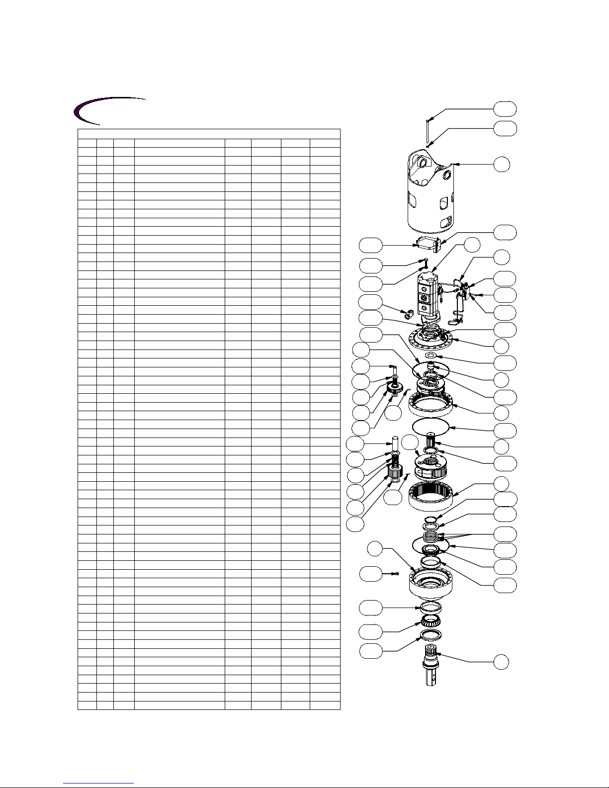
Exploded View Drawing
KICKDOWN MODEL 75 SERIES (HYDRASYNC) AUGER DRIVE
29.58:137.80:140.25:151.43:1DESCRIPTIONQTYITEMGROUP
75-004-301275-004-301275-004-301275-004-3012BEARING CARRIER11
25-004-101225-004-101225-004-101225-004-1012RING GEAR- PRI12
25-004-102225-004-102225-004-102225-004-1022RING GEAR- SEC13
25-004-122225-004-122225-004-122225-004-1222
COVER
14
25-004-117225-004-117225-004-116225-004-1162INPUT GEAR15
25-005-201125-005-201125-005-200125-005-2001CARRIER ASSY-PRI1
-
6
25-004-104225-004-104225-004-103225-004-1032CARRIER - PRI16A
25-004-111225-004-111225-004-110225-004-1102PLANET GEAR - PRI36B
25-004-103125-004-103125-004-103125-004-1031PLANET SHAFT - PRI36C
81-004-156181-004-156181-004-156181-004-1561THRUST WASHER - PLANETS66D
01-105-057001-105-057001-105-057001-105-0570BEARING36E
01-153-002001-153-002001-153-002001-153-0020ROLL PIN36F
25-005-204125-005-203125-005-204125-005-2031
CARRIER ASSY - SEC
1
-
7
25-004-107225-004-106225-004-107225-004-1062CARRIER - SEC17A
25-004-109225-004-108225-004-109225-004-1082PLANET GEAR - SEC37B
25-004-102125-004-102125-004-102125-004-1021PLANET SHAFT37C
25-004-104125-004-104125-004-104125-004-1041PLANET WASHER67D
01-105-055001-105-055001-105-055001-105-0550BEARING37E
01-105-056001-105-056001-105-056001-105-0560BEARING37F
01-153-019001-153-019001-153-019001-153-0190ROLL PIN37G
----
SHAFTS1
-
8
75-004-402275-004-402275-004-402275-004-4022
OUTPUT SHAFT - 2-5/8 HEX
-
75-004-401275-004-401275-004-401275-004-4012
OUTPUT SHAFT - 3" HEX
-
25-004-115225-004-114225-004-115225-004-1142SUN GEAR - SEC.19
----
THRUST WASHERS
--
10
25-004-113225-004-113225-004-113225-004-1132CARRIER THRUST WASHER210A
81-004-288381-004-288381-004-288381-004-2883INPUT THRUST WASHER110B
----
SEALS & 0-RINGS
--
11
01-405-050001-405-050001-405-050001-405-0500OUTPUT SHAFT SEAL111A
01-402-002001-402-002001-402-002001-402-0020O-RING311B
01-402-001001-402-001001-402-001001-402-0010
O-RING
1
11C
----
OUTPUT SHAFT BEARINGS
--
12
01-102-025001-102-025001-102-025001-102-0250INNER BEARING CONE112A
01-103-025001-103-025001-103-025001-103-0250INNER BEARING CUP112B
01-102-012001-102-012001-102-012001-102-0120OUTER BEARING CONE112C
01-103-011001-103-011001-103-011001-103-0110OUTER BEARING CUP112D
----
HARDWARE
--
13
01-150-166001-150-166001-150-166001-150-1660HEX HEAD CAP SCREW (1/2-13 X 7.5)2013A
01-150-011001-150-011001-150-011001-150-0110HHCS (5/8-11 X 1-3/4)213B
01-166-012001-166-012001-166-012001-166-0120
FLATWASHER - HDN (1/2 X 7/8 X 1/8)
20
13C
01-166-004001-166-004001-166-004001-166-0040
LOCKWASHER - 5/8 ZINC PLATED
213D
01-150-169001-150-169001-150-169001-150-1690HHCS (1/4-20 X 1.75)213E
01-166-039001-166-039001-166-039001-166-0390FLAT WASHER (1/4)213F
----
PLUGS AND GREASE FITTINGS
--
14
01-207-004101-207-004101-207-004101-207-0041PLUG - 1/2 NPT MAGNETIC114A
01-208-003001-208-003001-208-003001-208-0030HOLLOW HEX PLUG (05HP-12)114B
----
BAIL ASSEMBLIES1
-
15
75-005-222275-005-222275-005-222275-005-22222" BOSS - BACKHOE M50 MOTORS
--
75-005-208275-005-208275-005-208275-005-2082
1.5" BOSS, M50 MOTORS
--
75-005-222275-005-222275-005-222275-005-2222
2" BOSS M50 MOTORS
--
----
MISCELLANEOUS
--
16
25-004-105125-004-105125-004-105125-004-1051SHIM*16A
25-004-106125-004-106125-004-106125-004-1061SUPPORT RING (250)116B
01-160-060001-160-060001-160-060001-160-0600RETAINING RING116C
01-365-002001-365-002001-365-002001-365-0020BAND CLAMP116D
01-360-004001-360-004001-360-004001-360-0040BRACKET116E
01-308-015001-308-015001-308-015001-308-0150VALVE BODY 2-DIRECTION116F
01-316-002001-316-002001-316-002001-316-0020
FITTING-16-16 TO -4 KICKDOWN
1
16G
----
MOTORS
1
-
17
01-304-060001-304-060001-304-060001-304-0600MOTOR - C.S. M50 1.5 X 2.5 (HI) (SPL SEAL)
--
01-304-061001-304-061001-304-061001-304-0610MOTOR - C.S. M51 2.5 X 2.5 (HI) (SPL SEAL)
--
----
TUBE KIT1
-
18
01-309-060001-309-060001-309-060001-309-0600KIT - TUBE ASSY. & FITTING KICDOWN 60
--
01-309-061001-309-061001-309-061001-309-0610KIT - TUBE ASSY. & FITTING KICDOWN 61
--
Eskridge
18
13A
13C
15
16E
16D
13B
13D
16G
16F
13E
13F
11C
14B
4
10B
5
11B
10A
6A
6C
6D
6E
6B
6D
6F 2
11B
9
10A
7A
7C
7D
7F
7E
7B
7D
7G
3
16B
16C
16A
11B
12A
12B
14A
1
12D
12C
11A
8
X75K2 ab ECN:3451E 07-11-12 HWP
* NUMBER OF SHIMS DEPENDANT UPON BEARING PRELOAD.
EFFECTIVE
FROM: S/N 102358 07-01-2012
TO: CURRENT
17

!
WARNING: While working on this equipment, use safe lifting procedures,
wear adequate clothing and wear hearing, eye and respiratory protection.
Model 75K2 service manual, SM75K2_0413 Page 3
Eskridge, Inc. Olathe, KS. 913-782-1238 www.eskridgeinc.com
LUBRICATION & MAINTENANCE
Operating Position
Single stage
Oil Capacity
Double stage Triple stage
Oil Level
Vertical Shaft (Pinion Down) 10 pts / 4.7 liters To midway on upper/
primary gear set
Using the chart below, determine an appropriate lubricant viscosity. Use only EP (extreme pressure) or API GL-5 designated lubricants.
Change the lubricant after the first 50 hours of operation and at 500 hour intervals thereafter. The auger drive should be partially disas-
sembled to inspect gears and bearings at 1000 hour intervals.
80W90 conventional
75W90 conventional
85W140 conventional
75W90 synthetic
80W140 synthetic
Note: Ambient temperature is the air temperature measured in the immediate vicinity of the gearbox. A gearbox exposed to the direct rays of
the sun or other radiant heat sources will operate at higher temperatures and therefore must be given special consideration. The max operating
temp must not be exceeded under any circumstances, regardless of ambient temperature.
If your unit was specified “shaft up” or with a “-Z” option, a grease zerk was provided in the base housing. For shaft-up operation, the
output bearing will not run in oil and must be grease lubricated. Use a lithium based or general purpose bearing grease sparingly every
50 operating hours or at regular maintenance intervals. Over-greasing the output bearing should be avoided as it tends to fill the housing
with grease and thicken the oil
Recommended ambient and operating temperatures for conventional and synthetic gear lubricants
-50 -25 0 25 50 75 100 125 150 175 200 225 250 F
-45 -32 -18 -4 10 24 38 52 66 79 93 107 121 C
Min Ambient/operating temp Max Operating temp
Max Ambient temp
ESKRIDGE MODEL 75 OIL CAPACITY
ESKRIDGE PART NUMBER INTERPRETATION
Note: All non custom Eskridge Geardrives are issued a descriptive part number which includes information regard-
ing the Model, means of shaft retention, base style, shaft style, input mounting, input shaft size, overall ratio and
various available options. For a detailed breakdown of this information, please refer to Eskridge product specifica-
tion sheets found at: http://www.eskridgeinc.com/diggers/diggerprodspecs.html

Model 75K2 service manual, SM75K2_0413 Page 4
Eskridge, Inc. Olathe, KS. 913-782-1238 www.eskridgeinc.com
Unit Disassembly Procedure
1) Scribe a diagonal line across the outside of the unit from
the bail (15) to the base (1) before disassembly to aid in the
proper positioning of pieces during reassembly.
2) Remove magnetic drain plug (14A) and drain oil from unit.
The oil will drain out faster and more completely if warm.
3) Disconnect the kickdown tube from the large fitting (16G) on
the motor (17) outlet port. Remove the large fitting.
4) Remove the twenty hex-head capscrews (13A) and
flat washers (13C).
5) Separate bail (15) from cover (4) and remove from digger
assembly.
6) Inspect kickdown tube kit (18) and valve body (16F). If nothing
is damaged, no replacement or service is necessary. Leave
the tube kit and valve body assembled on the motor for the
remainder of the unit disassembly and inspection. If there is
damage, the tube kit must be replaced as a complete kit.
7) Remove hex-head capscrews (13B) and lockwashers (13D)
and remove motor (17) from cover (4).
8) Remove cover (4), thrust washers (10B & 10A), and input gear
(5). Inspect o-ring (11B); discard if damaged or deformed.
9) Lift Stage I planet carrier assembly (6) out of the unit
Remove ring gear (2) and inspect o-ring (11B); discard if
damaged or deformed.
10) Remove secondary sun gear (9) and thrust washer (10A).
11) Lift the Stage II planet carrier assembly (7) out of the unit.
12) Remove the Stage II ring gear (3). Inspect o-ring (11B); as
before, discard if damaged.
13) The unit is now separated into subassemblies. The area(s)
requiring repair should be identified by thorough inspection
of the individual components after they have been cleaned
and dried.
Stage I
Carrier Subassembly
(Items 6A, 6B, 6C, 6D, 6E & 6F)
Disassembly
1) Rotate planet gears (6B) to check for abnormal noise or
roughness in bearings (6E) or planet shafts (6C). If further
inspection or replacement is required, proceed as follows.
NOTE: Support only the carrier (6A) while pressing out planet
shafts.
2) Drive roll pins (6F) completely into the planet shafts (6C).
3) Press or drive planet shafts (6C) out of carrier (6A).
4) Remove planet gears (6B) and thrust washers (6D) from the
carrier (6A).
5) Inspect the planet gear (6B) bearing bore, planet shaft (6C)
and bearings (6E). Check for spalling, bruising or other dam-
age. Replace components as necessary.
6) Check primary planet shafts (6C) for any abnormal wear,
especially ones where bearings needed to be replaced.
If any abnormal wear is found, replace planet shafts.
7) Use 3/16 inch pin punch to remove roll pins (6F) from planet
shafts (6C).
NOTE: If either the bearings or the planet shafts (pins) are
damaged, both components should be replaced.
Reassembly
1) Install bearing (6E) into planet gear (6B). Place one thrust
washer (6D) on each face of the planet gear. Install gear
assembly into carrier (6A).
2) Planet shafts (6C) should be installed with chamfered end of
3/16 inch hole toward outside diameter of the carrier (6A).
This will aid in alignment of holes while inserting roll pins
(6F).
3) Drive a roll pin (6F) through the carrier hole and into the planet
shaft to retain the parts. Repeat for other planet gears.
Stage II
Carrier Subassembly
(Items 7A, 7B, 7C, 7D, 7E, 7F, & 7G)
Disassembly
1) Rotate planet gears (7B) to check for abnormal noise or
roughness in bearings (7E & 7F). If further inspection or
replacement is required, proceed as follows.
2) Drive roll pins (7G) completely into the planet shafts (7C).
3) Slide planet shafts (7C) out of carrier (7A).
4) Remove planet gears (7B), washers (7D) and bearings (7E &
7F) from carrier (7A).
6A
6C
6D
6E
6B
6D
6F
7A
7C
7D
7F
7E
7B
7D
7G
Model 75K2 service manual, SM75K2_0413 Page 5
Eskridge, Inc. Olathe, KS. 913-782-1238 www.eskridgeinc.com
5) Inspect the planet gear (7B) bearing bore, planet shaft (7C)
and bearings (7E & 7F). Check for spalling, bruising or other
damage. Replace components as necessary.
6) Remove roll pins (7G) from primary planet shafts (7C) using
a 3/16 inch pin punch.
Reassembly
1) Rebuild primary planet carrier assembly in reverse order
using any needed new parts.
2) Install bearing (7E & 7F) into planet gear (7B). Place one
thrust washer (7D) on each face of the planet gear. Install
gear assembly into carrier (7A).
3) Planet shafts (7C) should be installed with the chamfered
end of the 3/16 inch hole towards the outside diameter of the
carrier (7A); this will aid in alignment of holes while inserting
roll pins (7G).
4) Drive roll pin (7G) into the carrier hole and into the planet
shaft to retain the parts. Repeat for remaining planet gears.
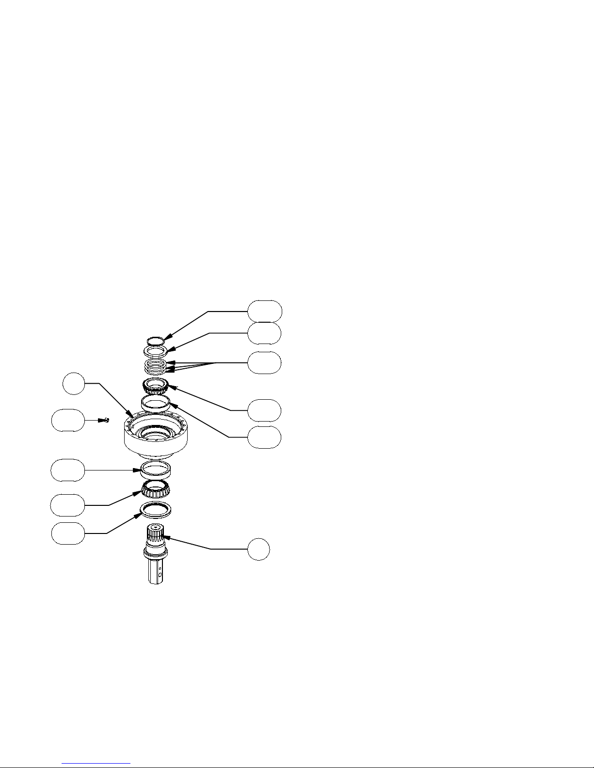
Base Subassembly
(Items 1, 8, 11A, 12A, 12B, 12C, 12D, 14A, 16A, 16B, 16C)
Disassembly
1) Remove the retaining ring (16C), support ring (16B) and
shims (16A).
Caution: Since the output shaft is no longer retained, care
should be taken to avoid personal injury. Care should also be
taken not to damage it when it is pressed through base.
2) Base (1) should be set shaft side down, as shown, on a plate
or table. Press output shaft (8) through the bottom of base
by applying a load to top end (internal end) of shaft until it
passes through inner shaft bearing cone (12A).
Note: Removing the shaft from the base assembly damages
the shaft seal and the seal will need to be replaced.
3) A gear puller may be used to remove the outer bearing cone
(12C) from the shaft (8). If reusing old bearing cone, do not
pull on or damage roller cage. Remove the shaft seal (11A)
from the shaft for replacement.
4) Inspect inner and outer bearing cups (12B & 12D). If cups are
damaged, drive them out using a brass drift and utilizing the
bearing knock-out notches in the base (1)
Reassembly
1) Clean all foreign material from magnetic oil plug (14A) locat-
ed on the side of the base (1).
2) Place base (1) (output side up, opposite shown) on the ta-
ble.
3) Apply a layer of lithium or general purpose bearing grease to
the roller contact surface of outer bearing cup (12D).
4) Press outer bearing cone (12C) (large end down as shown)
onto the shaft (8) until it seats against the shoulder.
Note: Press bearing cone onto output shaft by pressing on in-
ner race only. DO NOT press on roller cage, as it may damage
bearing.
5) Place the shaft (8) with the bearing (12C) into the base (1).
6) Flip this assembly, resting the base (1) on the end of the out-
put shaft (8).
7) Apply a layer of lithium or general purpose bearing grease to the
roller contact surface of the inner bearing cup (12B). Press the
inner bearing cone (12A) (large end up as shown) onto the
shaft (8) until it is seated against inner bearing cup.
8) Without the shaft seal (11A) installed, the preload may result
in a rolling torque that varies between 50 to 300 in-lb. The
bearing preload should be tailored to your application; a low-
speed application may require a high pre-load, high-speed
applications usually benefit from low pre-load. Adding shims
(16A) will increase the pre-load on the bearing set. Determine
your pre-load requirement and install shims to obtain this pre-
load. Place the support ring (16B) over the shims (16A) and
install the retaining ring (16C) into the groove in the shaft
(8).
9) Lubricate inner lip of new shaft seal (11A) and slide it onto the
shaft (8) and over the shaft seal diameter then press the seal
into the base bore (1).
16B
16C
16A
12A
12B
14A
1
12D
12C
11A
8
Table of contents
Other Eskridge Construction Equipment manuals


