Thern 5BH5 User manual

Owner's Manual
For
5BH5 Hitch Mounted Crane Base
IMPORTANT: Please record
product information on
page 2. This information is
required when calling the
factory for service.
A28390-A-0921
ORIGINAL TEXT
Read this Owner’s Manual
thoroughly before operating
the equipment. Keep it with
the equipment at all times.
Replacements are available
from Thern, Inc., PO Box 347,
Winona, MN 55987,
507-454-2996.
www.thern.com
Thern
Winches & Cranes

Owners Manual for the 5BH5 Hitch Mount Base for Davit Cranespage 2
A28390-A-0921
Two-Year Limited Warranty
Thern, Inc. warrants its products against defects in material or workmanship for two years from the date of purchase
by the original using buyer, or if this date cannot be established, the date the product was sold by Thern, Inc. to the
dealer. To make a claim under this warranty, contact the factory for an RGA number. The product must be returned,
prepaid, directly to Thern, Inc., 5712 Industrial Park Road, Winona, Minnesota 55987. The following information
must accompany the product: the RGA number, the date of purchase, the description of the claimed defect, and a
complete explanation of the circumstances involved. If the product is found to be defective, it will be repaired or
replaced free of charge, and Thern, Inc. will reimburse the shipping cost within the contiguous USA.
This warranty does not cover any damage due to accident, misuse, abuse, or negligence. Any alteration, repair or
modication of the product outside the Thern, Inc. factory shall void this warranty. This warranty does not cover any
costs for removal of our product, downtime, or any other incidental or consequential costs or damages resulting from
the claimed defects. This warranty does not cover brake discs, wire rope or other wear components, as their life is
subject to use conditions which vary between applications.FACTORY AUTHORIZED REPAIR OR REPLACEMENT
AS PROVIDED UNDER THIS WARRANTY IS THE EXCLUSIVE REMEDY TO THE CONSUMER. THERN,
INC. SHALL NOT BE LIABLE FOR ANY INCIDENTAL OR CONSEQUENTIAL DAMAGES FOR BREACH OF
ANY EXPRESS OR IMPLIED WARRANTY ON THIS PRODUCT. EXCEPT TO THE EXTENT PROHIBITED
BY APPLICABLE LAW, ANY IMPLIED WARRANTY OF MERCHANTABILITY OR FITNESS FOR A
PARTICULAR PURPOSE ON THIS PRODUCT IS LIMITED IN DURATION TO THE DURATION OF THIS
WARRANTY. Some states do not allow the exclusion or limitation of incidental or consequential damages, or allow
limitations on how long an implied warranty lasts, so the above limitation or exclusion may not apply to you. This
warranty gives you specic legal rights, and you may also have other rights which vary from state to state.
Note: Thern, Inc. reserves the right to change the design or discontinue the production of any product without
prior notice.
About This Manual
The Occupational Safety and Health Act of 1970 states that it is the employer’s
responsibility to provide a workplace free of hazard. To this end, all equipment
should be installed, operated, and maintained in compliance with applicable
trade, industrial, federal, state, and local regulations. It is the equipment owner's
responsibility to obtain copies of these regulations and to determine the suitability
of the equipment to its intended use.
This Owner’s Manual, and warning labels attached to the equipment, are to serve
as guidelines for hazard-free installation, operation, and maintenance. They should
not be understood to prepare you for every possible situation.
The information contained in this manual is applicable only to the Thern 5BH5
Hitch Mounted Crane Base. Do not use this manual as a source of information for
any other equipment.
The following symbols are used for emphasis throughout this manual:
Failure to follow ‘WARNING!’ instructions may result in equipment damage,
property damage, and/or serious personal injury.
Failure to follow ‘CAUTION!’ instructions may result in equipment damage,
property damage, and/or minor personal injury.
Important!
Failure to follow ‘important!’ instructions may result in poor performance of
the equipment.
Please record the following:
Date Purchased:
Crane Model No.:
Crane Serial No.:
If sold with a winch:
Winch Model No.:
Winch Serial No.:
This information is required when
calling the factory for service.
page 3
A28390-A-0921
Owners Manual for the 5BH5 Hitch Mount Base for Davit Cranes
Suggestions for Safe Operation
DO the following:
Read and comply with the guidelines set forth in this Owner’s Manual. Keep
this manual, and all labels attached to the crane, readable and with the
equipment at all times. Contact Thern, Inc. for replacements.
Follow all suggestions in the “Suggestions for Safe Operation” section of the
Owner’s Manual supplied for the respective davit crane designed for use with
this hitch mounted base.
Position the hitch mounted crane base on rm ground such that the crane is
level. An uneven base may cause the boom to rotate in the direction the mast
is leaning.
Attach the hitch mounted crane base only to a 2 inch x 2 inch Class III or
better receiver hitch. The receiver hitch must be properly installed by a
qualied service technician.
Use the equipment in a clear location that is away from oncoming trac or
other hazards.
When done working, always remove the hitch mount from the vehicle.
DO NOT do the following:
Do not lift people, or things over people. Do not walk or work under a load or
in the line of force of any load.
Do not exceed the load rating of the crane or any other component in the
system. To do so could result in failure of the equipment.
Do not install non-standard davit cranes onto the hitch mounted base without
authorization from Thern, Inc.
Do not operate or apply loads without all pins securely in place.
Do not adjust support leg positions while the crane is loaded.
Do not use the hitch mount crane base with lightweight or otherwise unstable
vehicles that may move during operation.
Do not move the vehicle with the hitch mount attached.
Owners Manual for the 5BH5 Hitch Mount Base for Davit Cranespage 4
A28390-A-0921
1.1 Installing the Hitch Mounted Base
Position the hitch mounted crane base on rm ground such that the crane is
level. An uneven base may cause the boom to rotate in the direction the mast
is leaning.
Attach the hitch mounted crane base only to a 2 inch x 2 inch Class III or
better receiver hitch. The receiver hitch must be properly installed by a
qualied service technician.
Use the equipment in a clear location that is away from oncoming trac or
other hazards.
Do not use the hitch mount crane base with lightweight or otherwise unstable
vehicles that may move during operation.
1.1.1 STUDY PARTS DRAWINGS to understand how the hitch mounted base is
assembled. See page 8.
1.1.2 LOCATE THE EQUIPMENT in an area clear of trac and obstacles that
could interfere with operation. Set the vehicle’s parking brake.
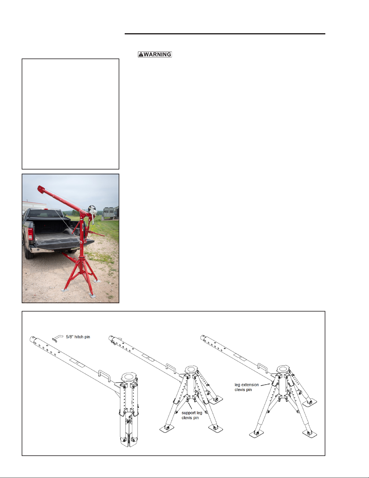
1.1.3 ASSEMBLE THE BASE for the crane to be located directly behind the
vehicle. See Figure 1. Skip to section 1.1.4 if you want the crane positioned
to the left or right of the vehicle.
a INSERT THE BASE PIPE assembly into the receiver hitch. Secure in place
with the provided 5/8” hitch pin.
b REMOVE THE CLEVIS PINS to spread the support legs. Reinstall the
clevis pins to secure this position.
c REMOVE THE CLEVIS PINS to extend the support legs. There are various
support leg height positions to accommodate dierent truck sizes and uneven
ground. Reinstall the clevis pins to secure the support legs at the desired
height. Make sure the base is level. The support legs should be able to
extend if necessary during operation.
Important!
• Inspect the hitch mounted base
during assembly. This will give
you a record of the condition of
the base with which to compare
future inspections.
• Save all packaging that the base
was shipped in, to re-use if you
need to repackage the base.
• Contact the factory immediately
if any parts are missing or dam-
aged.
Figure 1 - Crane located behind the vehicle

page 5
A28390-A-0921
Owners Manual for the 5BH5 Hitch Mount Base for Davit Cranes
1.1.4 ASSEMBLE THE BASE for the crane to be located to the left or right of
the vehicle. See Figure 2.
a INSERT THE BASE HITCH “T” assembly into the receiver hitch. Secure
in place with the provided 5/8” hitch pin.
b INSERT THE BASE PIPE assembly into the hitch “T”. Secure in place with
the provided 5/8” hitch pin and then tighten thumb screws.
c REMOVE THE CLEVIS PINS to spread the support legs. Reinstall the
clevis pins to secure this position.
d REMOVE THE CLEVIS PINS to extend the support legs. There are various
support leg height positions to accommodate dierent truck sizes and uneven
ground. Reinstall the clevis pins to secure the support legs at the desired
height. Make sure the base is level. The support legs should be able to
extend if necessary during operation.
e ATTACH THE SUPPORT JACK and secure with the clevis pin supplied
with the jack. Rotate the handle to extend the leg to the ground. Check
again to make sure the base is level.
f TO USE THE PULLEY TO CHANGE ROPE DIRECTION, remove the
sheave from the base hitch “T”. Position the winch rope in the sheave’s
groove and reinstall the sheave onto the base hitch “T”. Loads can be pulled
horizontally at angles up to 45 degrees left or right. See Figure 3.
1.2 Installing the Crane into Hitch Base
1.2.1 ASSEMBLE THE CRANE using the Owner’s Manual provided with the
respective Thern crane purchased for this hitch mounted base.
1.2.2 ASSEMBLE THE ROTATION STOP assembly provided with the hitch
base to the crane using a 7/16” wrench and 5/32” hex key.
Figure 3 – Pully
(Top View)
Figure 2 - Crane located left or right of the vehicle
Owners Manual for the 5BH5 Hitch Mount Base for Davit Cranespage 6
A28390-A-0921
2.2 Preparing for Operation
Do not operate or apply loads without all pins securely in place.
Do not adjust support leg positions while the crane is loaded.
Do not use the hitch mount crane base with lightweight or otherwise unstable
vehicles that may move during operation.
2.2.1 CONSIDER THE OPERATION. Do not begin until you are sure you can
perform the entire operation without hazard.
2.2.2 SECURE THE VEHICLE. Make sure the vehicle’s engine is OFF with
automatic transmission in PARK or manual transmission in 1st gear. Engage
the parking brake and chock wheels for added safety.
2.2.3 INSPECT ALL COMPONENTS of the system.
a INSPECT THE CRANE and other equipment according to the Instructions
for Frequent Inspection.
b INSPECT THE WINCH according to the instructions in the Winch Owner’s
Manual.
c OPERATORS must be in good health, alert, thoroughly trained in operating
the equipment, and properly clothed (hard hat, safety shoes and safety
glasses, no loose clothing).
d THE LOAD must be clear of other objects and free to move. Make sure the
load will not tip, spin, roll away, or in any way move uncontrollably.
2.2.4 KNOW YOUR LOAD and make sure you do not exceed the load rating of
the crane or any other equipment in the system.
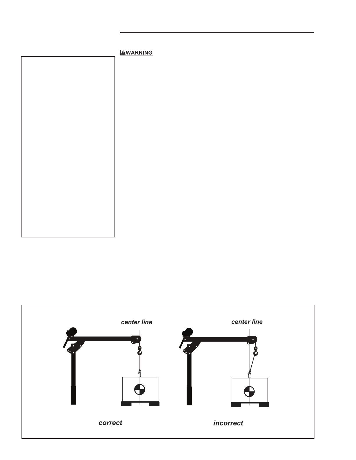
2.2.5 POSITION THE BOOM so the load hook is centered over the load.
Avoid side pulls which could damage the crane or cause the load to tip.
See Figure 4.
Important!
• When determining whether the
load will exceed the load rating,
consider the total force required
to move the load.
• Obey a stop signal from anyone.
• Maintain tension on the wire
rope to keep it tightly and evenly
wound on the drum.
• If the crane and load are
not visible during the entire
operation, get help from another
person.
• Appoint a supervisor if more
than one person is involved in
the operation. This will reduce
confusion and increase safety.
• When lifting a load, use a tag line
to keep the load from swinging or
twisting, while keeping yourself
away from the load.
Figure 4 – Positioning the Boom
page 7
A28390-A-0921
Owners Manual for the 5BH5 Hitch Mount Base for Davit Cranes
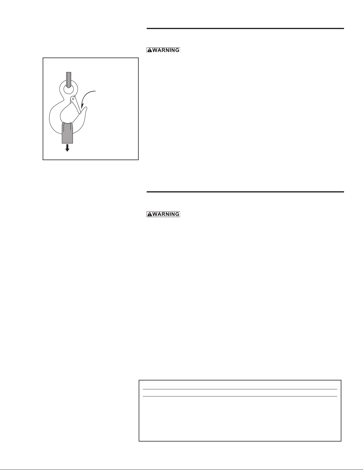
Figure 5 – Attaching Load
latch closed tight
against hook
sling seated in
saddle of hook
2.3 Attaching the Load
Do not wrap the wire rope around the load. This damages the wire rope and
could cause the load to escape. Use a sling or other approved lifting device.
2.3.1 CLEAR OBJECTS from the path of the load so you can move it freely and
observe it at all times during the operation.
2.3.2 MAKE SURE THE WIRE ROPE is not twisted. A twisted wire rope could
cause the load to spin when it is raised o the ground.
2.3.3 ATTACH THE LOAD using a nylon sling, or other approved lifting device.
Follow the recommendations of the sling manufacturer.
a SEAT THE SLING in the saddle of the hook with the hook latch completely
closed. See Figure 5.
b CENTER THE LOAD on the hook so it will remain balanced and not tip or
rotate to one side.
2.4 Moving the Load
Do not make adjustments to the crane or base while the crane is loaded.
2.4.1 MOVE THE LOAD slowly and smoothly, only a small distance at rst.
Make sure the load is balanced and securely attached before continuing.
2.4.2 OPERATE THE WINCH to raise or lower the load. Refer to the instructions
in the Winch Owner’s Manual.
2.4.3 OBSERVE THE WIRE ROPE as it winds onto the drum. If it becomes
loose, uneven, or overlapped, stop the operation and rewind the wire rope
before continuing. Continued operation with overlapped or uneven wire
rope can damage the wire rope and shorten its life.
2.4.4 ROTATE THE MAST AND BOOM to move the load side-to-side.
a ROTATE THE BOOM slowly and smoothly to avoid swinging the load or
causing shock loads. Do not jam the boom against other objects.
b CENTER THE LOAD on the hook so it will remain balanced and not tip or
rotate to one side.
Table 1 - Weight Chart
Base Component lbs (kg)
Main Assembly 47.6 (21.6)
Leg Extension (each) 4.8 (2.2)
Receiver “T” w/ Sheave 17.3 (7.8)
Support Jack 16.0 (7.2)
TOTAL 95.3 (43.2)
Owners Manual for the 5BH5 Hitch Mount Base for Davit Cranespage 8
A28390-A-0921
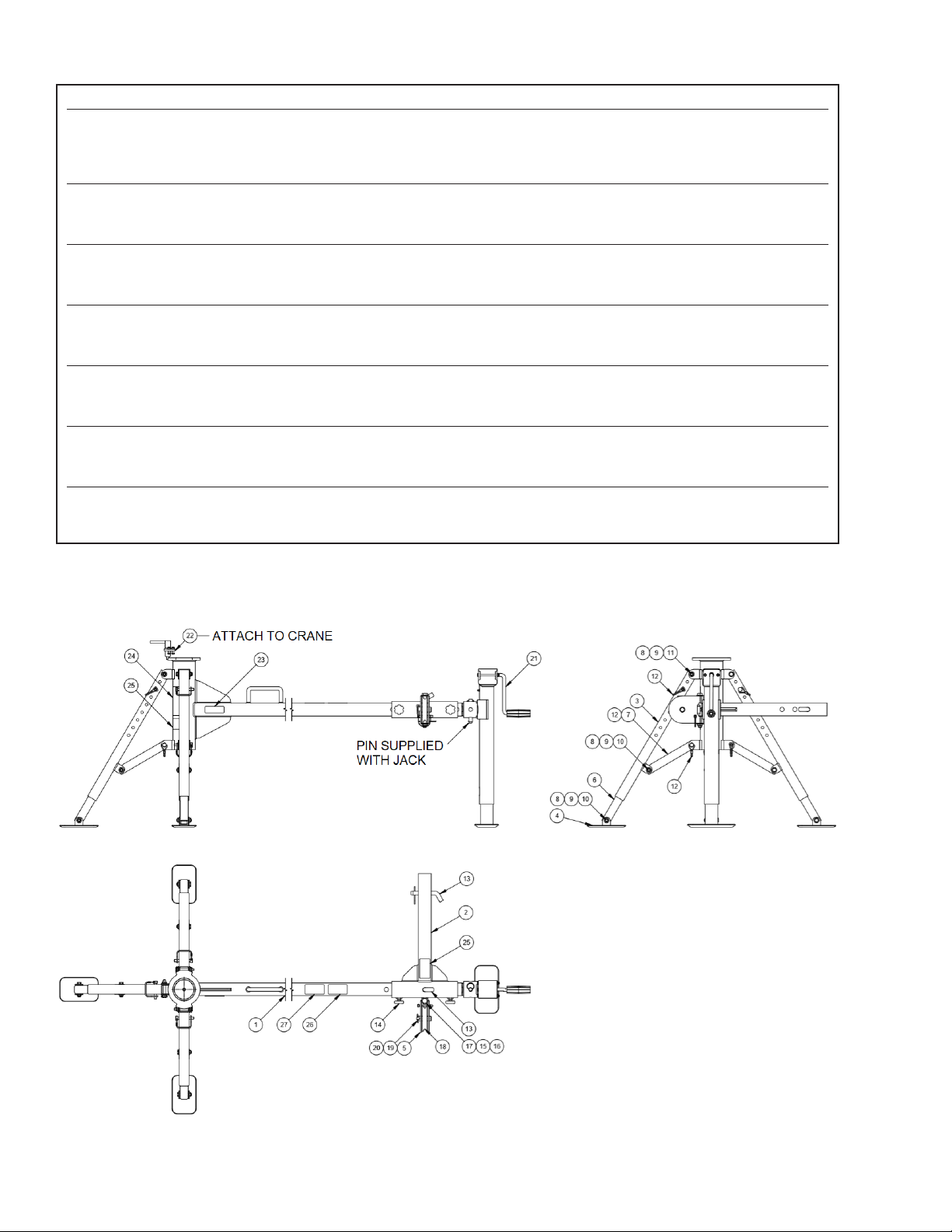
5BH5 Hitch Mount Base
item description part number qty.
1 WELDMENT BASE PIPE A27732 1
2 WELDMENT BASE HITCH T A27733 1
3 WELDMENT BASE LEG A27735 3
4 WELDMENT BASE FOOTPAD A27736 3
5 WELDMENT BASE SHEAVE A27737 1
6 BASE LEG TUBE EXTENSION A27826 3
7 BASE LEG SUPPORT A27828 3
8 WASHER FLT SAE .375 X .812 X .065 ZNPL A11973 18
9 NUT HEX JAM NYLK .375-16NC ZNPL GR2 A3180 9
10 CAPSCR HEXHD .375-16NC X 2.000 ZNPL GR5 A3495 6
11 CAPSCR HEXHD .375-16NC X 2.250 ZNPL GR5 A3494 3
12 PIN LINCH D .375 X 1.875 ZNPL A27832 6
13 PIN HITCH .625 X 3.000 EFF LENGTH ZNPL A27214 2
14 SCREW THUMB .375-16NC X .750 BLK A27831 2
15 WASHER FLT SAE .500 X 1.062 X .095 ZNPL A2932 2
16 NUT HEX JAM NYLK .500-13NC ZNPL GR2 A3176 1
17 CAPSCR HEXHD .500-13NC X 5.000 ZNPL GR5 A3247 1
18 SHEAVE ASSEMBLY B2462 1
19 PIN CLEVIS .750 DIA 5PT SHEAVE SST A12314 1
20 PIN LINCH D ASSY - SEE PRINT A12414SS 1
21 JACK ROUND SCREW 2000 LB. W/FOOTPLATE A27829 1
22 ROTATION STOP ASSEMBLY 5Px B6241 1
23 LABEL THERN 1.00 X 3.20 A6889 1
24 LABEL WARNING B5790 1
25 LABEL WARNING BEFORE LOADING B6229 2
26 LABEL WARNING VEHICLE STABILITY A27271 1
27 LABEL WARNING REMOVE HITCH MOUNT A27432 1

page 9
A28390-A-0921
Owners Manual for the 5BH5 Hitch Mount Base for Davit Cranes
NOTES:

Owners Manual for the 5BH5 Hitch Mount Base for Davit Cranespage 10
A28390-A-0921
NOTES:

page 11
A28390-A-0921
Owners Manual for the 5BH5 Hitch Mount Base for Davit Cranes
NOTES:

Thern, Incorporated
5712 Industrial Park Road
Winona, MN 55987
PH 507-454-2996
FAX 507-454-5282
EMAIL: [email protected]
www.thern.com
Thern Europe
Bedrijvenpark Twente 454e
7602 KM Almelo
Netherlands
PH +31-546-898-380
EMAIL: [email protected]
Thern
Winches & Cranes
Table of contents
Other Thern Construction Equipment manuals


Popular Construction Equipment manuals by other brands


Southwire
Southwire MAXIS Xtreme Bender MXB2000 operating instructions

Allied
Allied AR Series Safety, operation and maintenance

HIAB
HIAB 435K HiPro CD Operator's manual

MKT
MKT V-2Esc Service, Operating, Maintenance and Parts Manual

Falcon
Falcon RME Series OPERATION, PARTS AND REPAIR MANUAL

Fayat
Fayat Dynapac F80W operating manual