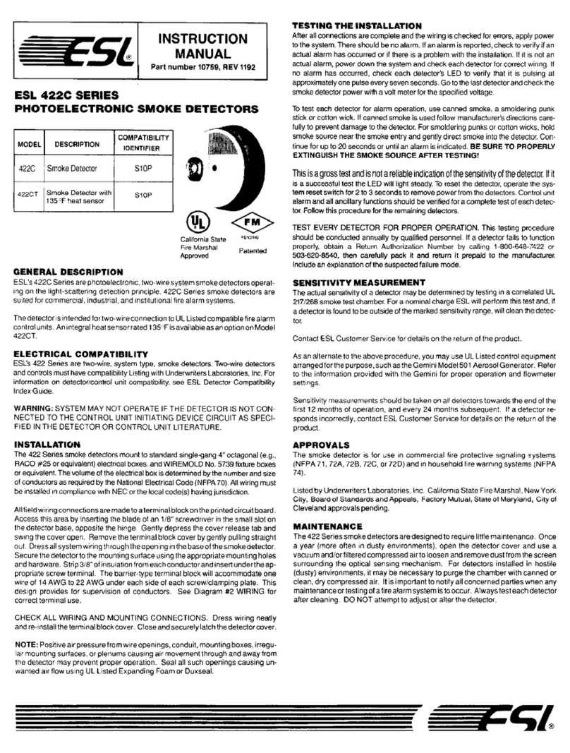
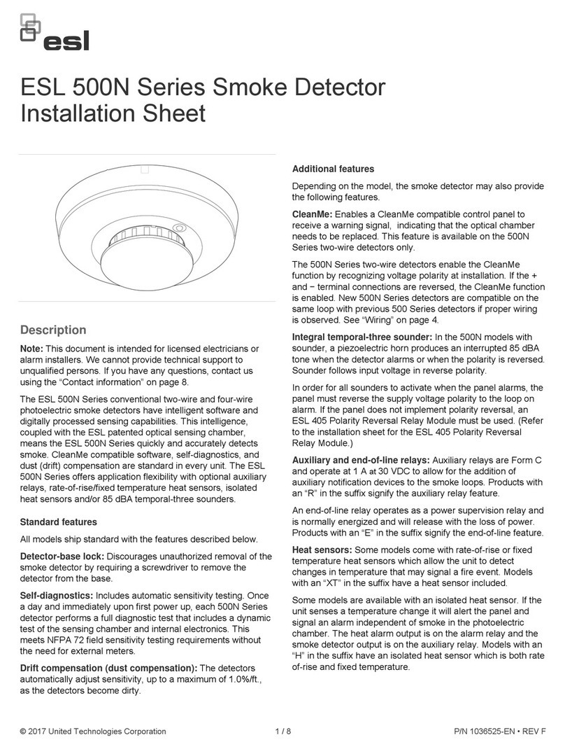
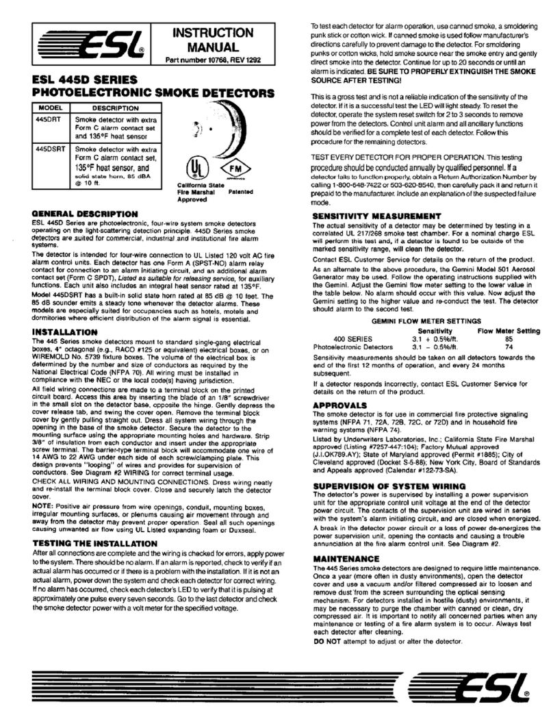
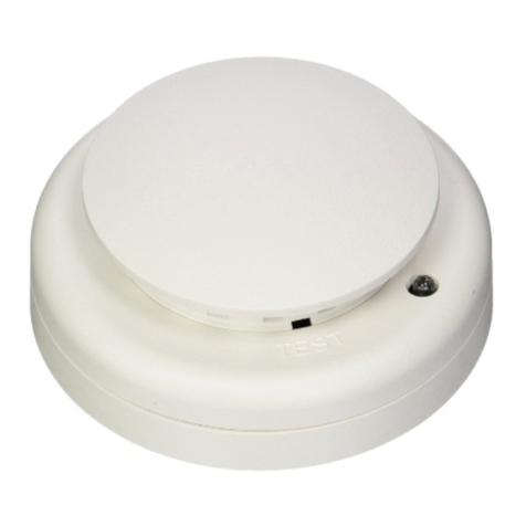
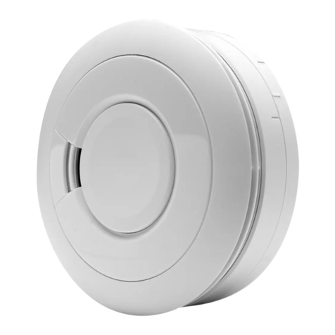
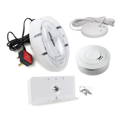
ESL 429 Series User manual

Two-Wire Compatibility
The ESL 429 Series two-wire, smoke detectors
offer the widest range of two-wire compatibility
in the industry. Refer to ESL’s Compatibility
Index for compatible control panel listings.
+
–
fire
alarm
initiating
circuit
models 429AT, 429C, 429CT,
429CST, 429CSST model 429CRT
END OF LINE
DEVICE
COMPATIBLE
LISTED
CONTROL UNIT*
first
detector last
detector
power
++--
auxiliary
contacts power
+
+
--
not used
429 & 428 Series Wiring Diagram
Diagram 2
GENERAL DESCRIPTION
TheESL429/449and428/448Serieslow-profile,self-diagnostic,two-
andfour-wiresmokedetectorsworkonthelightscatteringprinciple.A
pulsed infrared light-emitting diode serves as the light source, and a
high-speed photo-diode as the sensing element. This design has
superior protection against false alarms caused by dust, insects, RF
and ambient-light.
These Series of smoke detectors are especially suited for residential
occupancies,includinghotels,motelsanddormitories,aswellasother
commercial and industrial fire-system applications. This Series is
designedfor2-wire and 4-wireconnection,respectively, to 6-24VDC
fire alarm control panels, UL Listed for commercial or household fire
protection.
Plug-in terminal block
Diagram 1
ESL 429/449 & 428/448 SERIES
Self-Diagnostic Photoelectric
Smoke Detectors
Installation Instructions
Part Number 14153
California State Fire Marshal Approved
MEA (New York City) Approved
UL
LISTED
429/449
U
N
D
E
R
W
R
I
T
E
R
S
L
A
B
O
R
A
T
O
R
I
E
S
O
F
C
A
N
A
D
A
L
I
S
T
E
D
B
Y
428/448
+
–
DC
power
circuit
fire
alarm
initiating
circuit
models 449 & 448
AT, C, CT, CST, CSST
alarm
contact power
++--
models 449 & 448
CRT, CSRT, CLT, CSLT
auxiliary
contacts
(low temp output
CLT, SCLT) power
+
+
--
LISTED
CONTROL
UNIT
first
detector
alarm
contacts
model 448CSH*
power
+
+
--
heat sensor
contacts
model 449 & 448*
CSRH
local non-
latching
smoke alarm
contacts power
++
--
heat sensor
contacts
red
black
brown brown
POWER
SUPERVISION
UNIT
last
detector
Diagram 3
449 & 448 Series Wiring Diagram
*448CSH and 448CSRH are smoke alarms.
SMARTHOME™ 1-800-SMART-HOME 949-221-9200
http://www.smarthome.com Order #7309
firealarmresources.com

Optional Features
This Series includes a wide range of options, as shown in the Product
Selection Guide (Diagram 9) on back page. These options include a
built in sounder, an auxiliary relay, an integral heat detector, and an
isolated heat detector, to meet almost any application.
Self-Diagnostics Includes Automatic
Sensitivity Testing
Eachdetector in theSeriescontinually monitorsitsown sensitivity and
operational status. Once a day it performs a full diagnostic test that
includes dynamically testing the sensing chamber and internal elec-
tronics. If a detector drifts out of its UL Listed sensitivity range or fails
internal diagnostics, the alarm LED will flash once every second to
indicate trouble. This meets NFPA 72 field sensitivity testing require-
ments without the need for external meters.
NOTE: Connect to a power supply that will not automatically reset.
Since the self-diagnostics only indicate trouble after 27 hours, if the
power supply automatically resets every 24 hours the self-diagnostic
indication will never be signaled. (The smoke detector will still signal
alarm correctly.)
INSTALLATION
This Series of detectors mount to standard single-gang electrical
boxes, four-inch octagonal or four-inch square electrical boxes, or on
WIREMOLD No. 5739 fixture boxes. These detectors may also be
mounted directly to walls or ceilings where local codes/jurisdictions
permit.
First, pull wire through the electrical box and connect to the plug-in
terminal block supplied, one wire per terminal (see Diagrams 1, 2 and
3). Second, dress wiring neatly and snap the terminal block into the
back of the detector. Note: The detector cover must be closed com-
pletely, to support the circuit board, while installing the terminal block.
Now,openthecoverandmountthedetector,usingthemountingholes
provided (see Diagram 5).
All ESL smoke detectors are shipped with a plastic dust cover for use
inareaswhereconstruction is on-going.Smokedetectorswillnotwork
with the dust cover in place. Remove the dust cover when installation
is completed, prior to testing.
Smoke Detector Placement and Spacing
Ingeneralceilingmountedsmokedetectorsshouldbelocatednearthe
centeroftheroomorhallwheneverpossible,ormorethan4inches(100
mm) from any wall. When the detector is wall mounted, the top of the
detector should be 4 to 12 inches (100-300 mm) from the ceiling (see
Diagram 4). Refer to NFPA 72 for further mounting instructions.
Whenmorethanonedetectorisrequired,spacingof30feet(9.1meters)
may be used as a guide on smooth ceilings (as defined in NFPA 72).
Other spacing may be used depending on ceiling height, high air
movement, and other conditions or response requirements.
Low Temperature Output Models (CLT, CSLT Models)
Thesemodels havea separate relayoutput thatwill be energizedwhen
the ambient temperature around the detectors falls to approximately
43°F.Note:thisdetectorcontinuestohavethesameoperatingtempera-
ture range as standard models –32°F (0°C) to 120°F (50°C). Run 6
conductorfirewirefromacombinationburglar/firealarmpaneltosmoke
detector. Connect low temperature relay contact to a separate non-fire
zoneonacombinationburglar/firealarmcontrolpanel.Warning:Donot
connect low temperature output relay to fire alarm zone.
Where NOT To Place Detectors
One of the major causes of nuisance alarms is improper placement of
detectors.Avoidlocatingdetectorstooclosetokitchensorwoodstoves,
where smoke can be generated. Garages and furnace rooms are also
poor locations, due to exhaust fumes. Placing detectors too close to
bathroomscancauseproblemsfromsteamybathsorshowers.Alsodo
not install detectors where normal ambient temperature can be over
100°F(37.8°C),suchas attics. Referto NFPA72 formore information.
Supervision of System Wiring
Power wiring in four-wire systems is required by NFPA 72 to be
supervised.Thisisaccomplishedbyinstallingapowersupervisionrelay
attheend ofthedetectorpowercircuit. Thecontactsof thesupervision
relayarewiredinserieswiththesystem’salarminitiatingcircuit,andare
closedwhenenergized(seeDiagram3). Abreak inthedetectorpower
circuit or a loss of power de-energizes the power supervision relay,
opening the contacts and causing a trouble annunciation at the fire
alarm control unit.
ESL Models 204-6 V and 204-12/24 V are relays UL Listed for 4-wire
powersupervision. ESLModel204-12/24V CAN is arelayULCListed
for 4-wire power supervision. Models 449/448CTE, 449CSTE, and
449CSSTE are smoke detectors with a built-in end-of-line power
supervision relay, and can be used to supervise a circuit in place of a
powersupervision relay. The449CTE, 449CSTE, and449CSSTE will
also automatically send a trouble signal to the control panel whenever
thedetector needs maintenance. Proceed with sensitivity testing on all
detectors as outlined on next page.
Diagram 5
NOTE: Positive air pressure from wire openings, conduit, mounting boxes,
irregular mounting surfaces, or plenums causing air movement through
and away from the detector may prevent proper operation. Seal all
openings causing unwanted air flow using UL Listed expanding foam or
Duxseal.
mounting
all boxes
4" square or
WIREMOLD mounting
(No. 5739)
single gang 4"
octagon
mounting
cover release
test switch
6.1"
(15.5 cm)
1.85" (4.70 cm)
For instructions on removal
of terminal block and
circuit board call technical
services at 800-648-7424.
Diagram 4
ceiling
acceptable here
never here
4 in.
(100 mm)
4 in.
(100 mm)
minimum
12 in.
(300 mm)
maximum
top of detector
acceptable here
side
wall
NOTE:
measurements shown are to the
closest edge of the detector
Note: Measurements shown are to the closest edge of the detector.
SMARTHOME™ 1-800-SMART-HOME 949-221-9200
http://www.smarthome.com Order #7309
firealarmresources.com

without the need for external meters. In accordance with NFPA 72,
smoke detector sensitivity should be checked within one year after
installation and every alternate year thereafter, in commercial installa-
tions, or every three years in residential sites.
The replaceable sensing chamber of the 400 series photoelectric
detector unsnaps for easy field cleaning and service. Whenever the
status LED indicates cleaning is necessary, open the detector cover,
unsnap and throw away optical block chamber. Then thoroughly blow
off the optical base and snap a new optical block chamber (part #211)
back in place. NOTE: Be sure new optical block chamber is seated all
the way down. Close detector cover and verify sensitivity with the
sensitivity level test (below).
Sensitivity Level Test Mode
Each detector includes a sensitivity test mode that is activated by
holding a magnet near the integral reed switch for more than one
second (see Diagram 7). This initiates the self-diagnostic routine and
providesvisualindicationifserviceisrequired.ThealarmLEDprovides
the indication listed in Diagram 8.
Afterthesequence of blinks,ifthe sensitivity isfoundto be withinlimits
and if all other tests pass, the detector will go into alarm until reset by
the panel. If the sensitivity is not within limits, or an unserviceable
hardwarefault has been detected, the alarm LEDwill continueto flash
once per second until the detector is reset by
thepanel.Ifsensitivitytestindicatesanunacceptablelevel,takeaction
recommendedabove.Ifactiondoesnotresultinacceptablesensitivity,
replace unit.
Approvals
The smoke detector is for use in commercial fire protective signaling
systems and in household fire warning systems. (NFPA 72).
429/449 Series
Listedby UnderwritersLaboratories Inc.; California State FireMarshal
approved (Listing #7272-0447-128); MEA approved [New York City]
(Listing #MEA 64-94-E) Factory Mutual approved.
449CLT/449CSLT Series
Listed by Underwriters’Laboratories, Inc.
428/448 Series
Listed by Underwriters’Laboratories of Canada (Listing # CS205).
Testing the Installation
After all connections are complete and the wiring is checked for errors,
apply power to the system. There should be no alarm. If an alarm is
reported,determineifadetectorislatchedinalarmorifthereisaproblem
with the wiring.
Allsmokedetectorsshall be testedatleastannually in accordance with
NFPA 72. The preferred method for functional testing is with Smoke! in
a can®, available from ESL. Follow the instructions on the can carefully
to ensure proper testing. Other brands of canned smoke are not
recommended due to potential for contamination. Other acceptable
testing methods are; a smoldering punk stick or a cotton wick.
Thedetectorsamplesforsmokeaboutevery9seconds,whileflashing
its LED. If smoke is detected, the sampling increases to every 4.5
seconds. Excessive smoke must be detected in three consecutive
samplesforthealarmtoactivate. Therefore,whentestingthedetector
withsmolderingpunksorcottonwicks,holdthesmokesourcenearthe
smoke entry and gently direct smoke into the detector for 20 seconds
or until alarm is indicated. BESURETOPROPERLYEXTINGUISHTHE
SMOKE SOURCE AFTER TESTING!
This is a go/no-go test and is not a reliable indication of detector
sensitivity. If it is successful, the LED will remain lit. To reset the
detector, operate the system reset switch to remove power from the
detectors. Control unit alarm and all auxiliary functions should be
verified for a complete test of each detector.
Models with heat sensors sample for heat every 3 seconds. Test heat
sensors by using a hot air gun. Aim at heat sensor from 6-10" away.
Detector should go into alarm in less than 30 seconds. Be careful not
to melt plastics.
MAINTENANCE, CLEANING and
SENSITIVITY TESTING
Thisseriesofself-diagnosticsmokedetectorsisdesignedforeasyfield
service and maintenance. If a detector drifts beyond its approved
sensitivity range for more than 24 hours, or fails internal diagnostic
tests, the unit automatically indicates trouble by flashing its LED every
second. This meets NFPA 72 field sensitivity testing requirements
optical block cover
optical base
snap into indentation
indentation
SQUEEZE
HERE
LED
Diagram 6
Diagram 7 To activate sensitivity level test
mode, hold magnet on hinge side of
detector for more than 1 second.
magnet (for best results
position magnet slightly
off center)
Diagram 8
Approximate
obscuration Blinks Indication Action
(%/ft.)
429/449 428/448
1 Unserviceable hardware fault is detected Reset unit and re-run sensitivity test, if indication remains the same,
replace unit.
2.69 3.05 2 The detector is not sensitive enough Clean per instructions. Reset unit and re-run sensitivity test, if
2.46 2.75 3 indication remains the same, replace unit.
2.23 2.50 4 Detector is within sensitivity limits None
2.00 2.15 5
1.77 1.85 6
1.54 1.50 7 Detector is too sensitive Check to be sure optical block cover is snapped down completely.
1.31 1.25 8 Clean per instructions.
1.08 0.90 9
SMARTHOME™ 1-800-SMART-HOME 949-221-9200
http://www.smarthome.com Order #7309
firealarmresources.com

Sentrol reserves the right
to change specifications
without notice.
©1999 Sentrol
12345 SW Leveton Dr., Tualatin, OR 97062
Tel.: 503.692.4052 Fax: 503.691.7566
http://www.sentrol.com
U.S. & Canada: 800.547.2556
Technical Service: 800.648.7424
FaxBack: 1.800.483.2495
SENTROL
ESL
a product of sentrol
Diagram 9
Electrical Specifications
449CSRT
Series Designator
Wire Type
Features
Power Designator
Model Designator
* 429 models draw up to a maximum of 60mA alarm current if not limited by panel.
Product Data
Sensitivity
428/448 - minimum............... 2.0 + 0.50%/Ft.
- maximum .............. 2.0 - 0.50%/Ft.
429/449 - minimum............... 2.0 + 0.37%/Ft.
- maximum .............. 2.0 - 0.39%/Ft.
Operating temp .... 32°F to 120°F (0°C to 50°C)
Operating humidity range............. 0 to 95% RH
Sounder specifications.............. 85 dB at 10 Ft.
Color............................. white cover/white base
Field wiring size......................14-24 AWG
E-3914-0999
14153 Rev. B
Model Designator
Designator Listing
449 UL
448 ULC
Product Selection Guide Model Designator
Designator Power
A 6/12 V DC
C 12/24 V DC
Wire Type
Number Description
2 Two-wire only
4 Four-wire only
Max. Ripple Typ. Ave. Stby. Typ. Alarm Cur. Typ. Ave. Pol. Alarm Relay Other Relay
Model 2-Wire 4-Wire Min.Volt. Max. Volt. (PK To PK) Cur. (12-24V) (12-24V) Rev. Cur. Contacts Contacts
(V) (uA) (mA) (mA) (A) (A)
429AT, 428AT •6.5 20 10% 70 *see S09A –––
429C, 428C •8.5 33 10% 70 *see S10A –––
429CT, 428CT •8.5 33 10% 70 *see S10A –––
429CRT •8.5 33 10% 70 *see S11A ––2
429CST, 428CST,429CSST •8.5 33 10% 70 *see S11A 10 ––
449C, 448C •8.5 33 10% 70 15 –0.5 –
449CT, 448CT •8.5 33 10% 70 15 –0.5 –
449CRT •8.5 33 10% 70 31 –0.5 2
449CLT, 448CLT •8.5 33 10% 70 15 –0.5
449AT, 448AT •5.1 27 10% 70 15 –0.5 –
449CST, 448CST •8.5 33 10% 70 40 10 0.5 –
449CSRT •8.5 33 10% 70 51 10 0.5 2
449CSLT, 448CSLT •8.5 33 10% 70 40 10 0.5 –
449CSRH •8.5 33 10% 70 51 10 0.5 2
449CSST •8.5 33 10% 70 40 10 0.5 –
449CSTE, 449CSSTE •8.5 33 10% 23mA 51 33 0.5 2
449CTE, 448CTE •8.5 33 10% 23mA 31 23 0.5 2
448CSH** •8.5 33 10% 70 51 10 0.5 –
448CSRH** •8.5 33 10% 70 51 10 0.5 2
Power Supervision Units
204-6V (UL Listed) 5.1 15 –33 mA @ 6V DC ––0.5 –
14 mA @ 12V DC
204-12/24V (UL Listed) 8.5 33 –28mA @ 24V DC ––0.5 –
14 mA @ 12V DC
204-12/24V CAN (ULC Listed) 8.5 33 –28mA @ 24V DC ––0.5 –
Features
Built-in end-of-line relay that also acts as a sensitivity status output. For four wire only. Fail-safe relay trips upon loss of power or if
smoke detector is outside the approved sensitivity range for more than one day. End of line resistor is easily connected to terminal
with no extra wiring, or relay contacts can be connected to a separate trouble loop.
Isolated fixed 135°F (57°C) and rate of rise heat detector, independently trips the LED and alarm relay output. Smoke detector
activates internal sounder (local alarm) and auxiliary relay, but does not latch. Approved as both single station smoke alarm and
system heat detector. Ideal for hotel, motel and dormitory rooms where smoking is allowed.
Used to activate other devices such as elevator recall, door hangers, etc. UL Listed for releasing services.
85db built-in sounder alarms when smoke is detected or when power wiring polarity is reversed.
85db built-in sounder alarms when smoke is detected or when power wiring polarity is reversed. Also, chirps when unit goes outside
the approved sensitivity range for more than one day. Resetting detector will silence chirp for one day, until unity is restored to
proper sensitivity.
Integrated fixed 135°F (57°C) temperature and rate of rise head detector offers double protection. Either heat detector or smoke
detector can trip and latch LED and alarm relay outputs.
Non latching, low temperature output for temperatures below 43°F ±5°F (°C).
End-of-Line Power
Supervisory and Sensitivity
Status Relay
Isolated Fixed Temp. and
Rate of Rise Heat Detector
Auxiliary Relay
Built-in Sounder
Built-in Sounder with
Sensitivity Status Output
Integrated Fixed Temp. and
Rate of Rise Heat Detector
Low-Temperature Output
E
H
R
S
SS
T
L
Designator Feature Description
Heat detector specifications...fixed temperature - 135°F, 50 ft. spacing
rate of rise - 15°F/min. & > 105°F (8.3°C/min. & > 40.6°C)
Low temp specifications.........43°F (°C) ±5°F (°C)
Auxiliary relay contacts ..........2A @ 28 V DC or 120 V AC (resistive)
Alarm contacts .......................500 mA @ 36 V DC (resistive)
Detector size ..........................6.1 in. (15.5 cm) x D 1.85 in. (4.69 cm) x 8.8 oz. (0.25kg)W
Packaging ..............................10 detectors are packed in a carton
Self-diagnostic indication .......typically 27 hours after reset (do not connect to power
supply that resets every 24 hours)
©1999 Sentrol. Certain items in the Installation Instructions are protected under one or more of the following patents:5,546,074;
5,708,414; 5,798,701; 5,821,866; 5,936,533.
SMARTHOME™ 1-800-SMART-HOME 949-221-9200
http://www.smarthome.com Order #7309
firealarmresources.com
This manual suits for next models
35
Other ESL Smoke Alarm manuals
Popular Smoke Alarm manuals by other brands
ESYLUX
ESYLUX PROTECTOR K 10 PLUS Installation and operating instructions

System Sensor
System Sensor 2951 Installation and maintenance instructions
Gasmate
Gasmate GM160-018 manual
System Sensor
System Sensor FAAST FL0111E-HS Quick installation guide

Securiton
Securiton ASD 535 Application guidelines
System Sensor
System Sensor OSI-RE-SS Installation and maintenance instructions
