LEGRAND tynetec ZXT819 User manual

Tynetec, a business unit of Legrand Electric Ltd
Cowley Road, Blyth Riverside Business Park, Blyth, Northumberland, NE24 5TF.
Tel: +44 (0) 1670 352371 www.tynetec.co.uk
Trusted Technology
Caring for People
RadioLINK Hearing Impaired
Smoke Alarm Kit 869MHz
Caring for People
_________________________________________________________________________
________________________________________________________________
Doc No. FM0869 V1.00 Page 1
•Compatible with Reach IP and Advent XT2
•Complies with BS EN 14604:2005
•Mains powered strobe with rechargeable standby battery
•Plug-in vibrating pad with 1.5m lead
•Battery powered optical smoke alarm with integral sounder
•Mains powered telecare interface with rechargeable battery
•Devices communicate via RadioLINK wireless network
•Additional RadioLINK smoke, heat and CO detectors available
•RadioLINK network supports up to 12 devices, 30m range
•Strobe light dimensions: 180 x 110 x 85mm (HxWxD)
•Vibrating pad dimensions: 98mm diameter x 30mm deep
•Smoke alarm dimensions: 115mm diameter x 45mm deep
•Telecare interface dimensions: 90 x 190 x 39mm (HxWxD)
•Test button on smoke alarm and strobe unit
•Operating Temperature: 0oC to +40oC
•Telecare Transceiver: 869.2125MHz Class 1.5
•Low battery warning
•Digital Heartbeat
•Product Code: ZXT819
The RadioLINK hearing impaired smoke alarm kit is designed for
installation in dwellings occupied by deaf or hard of hearing
people. If fire is detected the smoke alarm will sound a loud
audible alert, the strobe unit will flash a strong white light
(excellent for day and night-time alerting) and the under-pillow
pad will vibrate to awake the heaviest sleeper.
A fire alarm call will also be transmitted to the ARC or the local
Manager via the telecare interface module.
Smoke Alarm Positioning
The smoke alarm should be sited at least 300mm from light
fittings and walls, ideally as centrally as possible in the room.
Smoke alarms should be positioned no more than 600mm below
the highest point in the room. If positioning on the wall, the top
of the smoke alarm must be between 150mm and 300mm below
the ceiling and at least 300mm from an adjacent wall.
Optical smoke alarms are less prone to false alarms from cooking
fumes and are therefore suitable for locating near kitchens. Like
other smoke alarms they can be susceptible to nuisance alarms
from steam and should not be placed near bathrooms. Refer to
the Manufacturer’s instruction booklet for more information on
positioning. Fitting the smoke alarm onto its base plate will
automatically switch-on its battery supply.
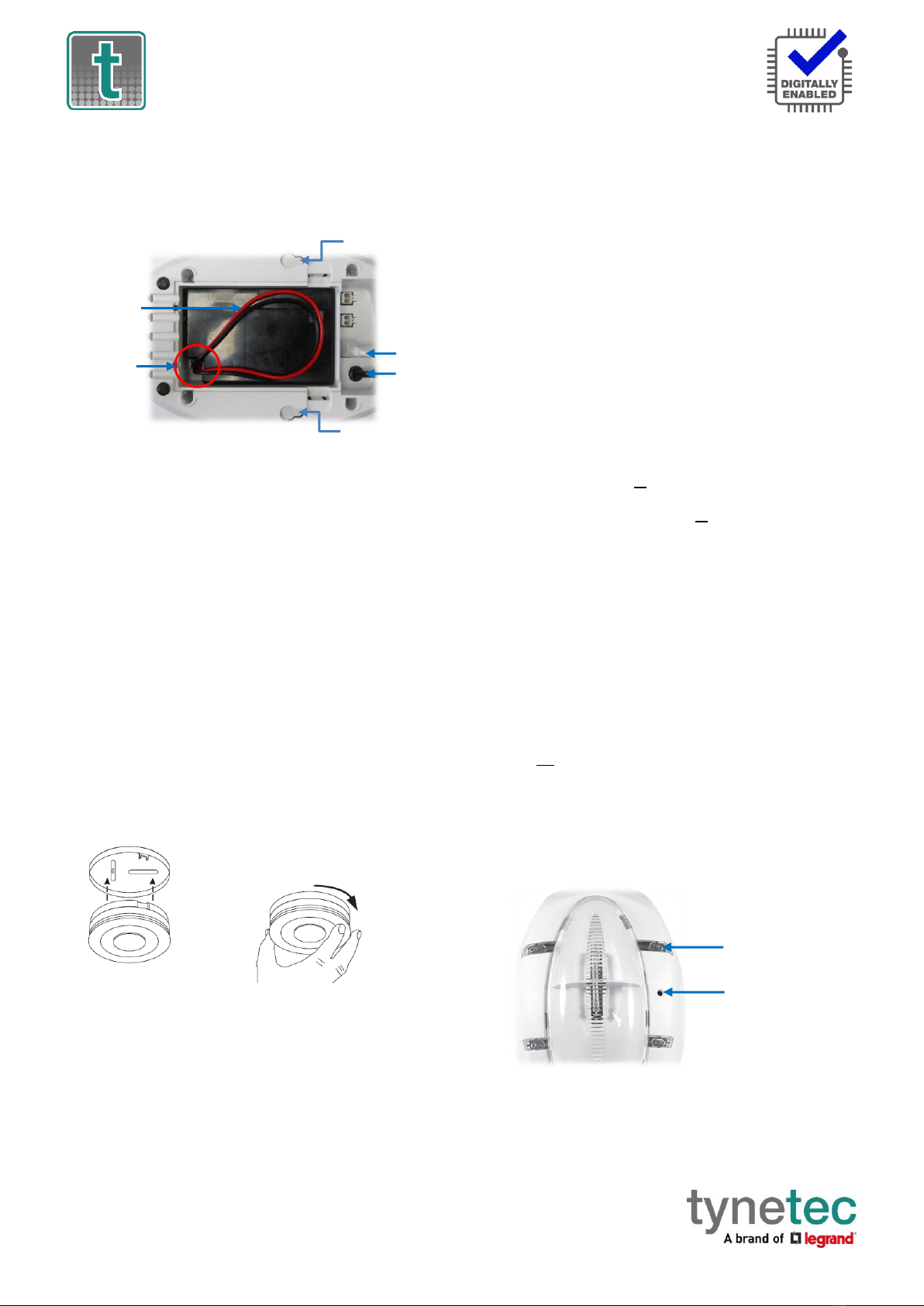
Strobe & Vibrating Pad Positioning
The strobe unit can be left free-standing on a bedside cabinet or
fixed to the wall so it can be seen from the bed. The vibrating pad
should be plugged-in to the strobe unit and placed under the
pillow. The strobe unit must have its standby battery fitted and
be plugged into the mains supply.
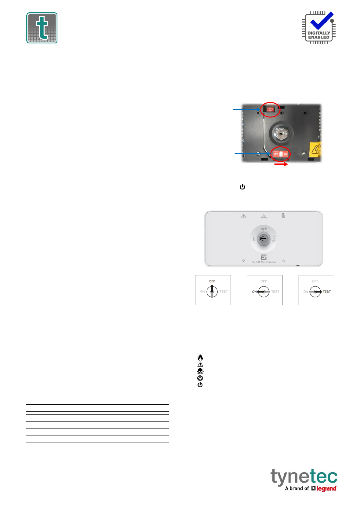
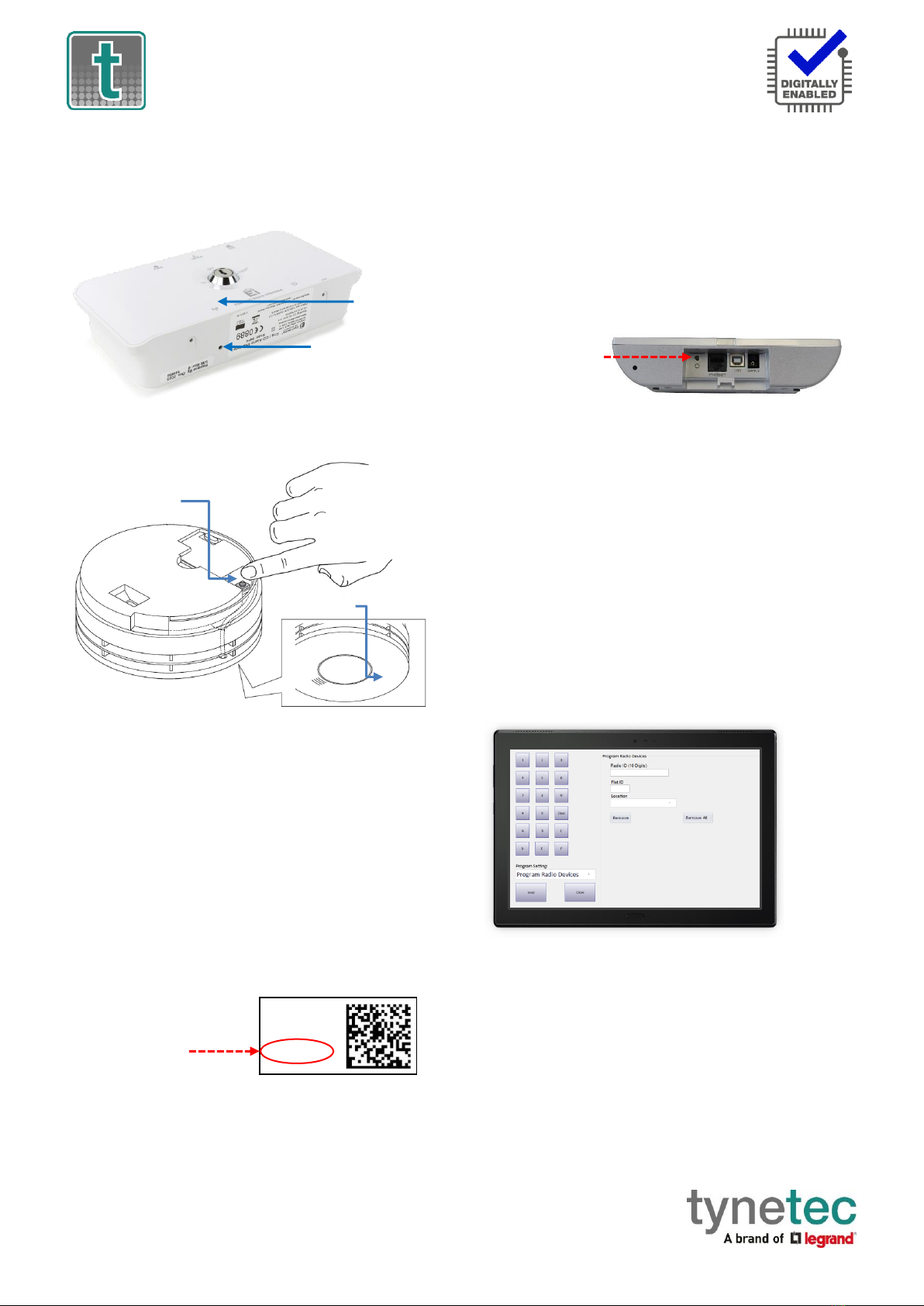
Telecare Interface Positioning
The telecare interface unit can be free-standing or fixed to the
wall somewhere out of sight. This communicates via the
RadioLINK network and must be within 30m of the smoke alarm
and strobe unit. The telecare interface unit must have its battery
switched on before being plugged into the mains supply.
Normal Operation
The green MAINS/STANDBY light on the strobe unit should be on
when the mains supply is connected. The green power light on
the telecare interface should also be on. Note: to conserve
battery life the smoke detector does not have any visual
indication that the power is on.
Alarm Condition
The smoke alarm will repeatedly sound loud beeps and the red
light will flash 2 times every second.
The red ALARM light on the strobe unit will flash once every 2
seconds, the white strobe light will flash 40 times a minute, and
the pillow pad will vibrate 2 seconds on/2 seconds off.
Check if there is a fire hazard and leave the building immediately.
DANGER: Never ignore any alarm. If you are not certain of the
cause, leave the building immediately.
Low Battery Condition
If the smoke alarm chirps every 32 seconds and the red light
flashes at the same time, this indicates the battery inside the
smoke alarm is running low. The complete smoke alarm must be
replaced as soon as possible.
The telecare transceiver battery (located inside the telecare
interface) is self-tested once a day, if it’s low for 7 consecutive
days a low battery condition will be reported once a week. The
transceiver should be replaced as soon as possible within 30 days.

Tynetec, a business unit of Legrand Electric Ltd
Cowley Road, Blyth Riverside Business Park, Blyth, Northumberland, NE24 5TF.
Tel: +44 (0) 1670 352371 www.tynetec.co.uk
Trusted Technology
Caring for People
RadioLINK Hearing Impaired
Smoke Alarm Kit 869MHz
Caring for People
_________________________________________________________________________
________________________________________________________________
Doc No. FM0869 V1.00 Page 2
Set DIP switches
1 ON and 2 OFF
Switch the
battery ON
In the OFF position
NO alarm calls or
test calls are
transmitted
In the ON position
only genuine
alarm calls are
transmitted
In the TEST position
genuine alarm calls
and test calls are
transmitted
⚫⚫
⚫
Fault Conditions
If the vibrating pad is disconnected the yellow FAULT light will
flash on the strobe unit once every 5 seconds and the white
strobe light will flash continuously (40/min).
If the mains supply is off and the strobe unit is operating on
battery power alone, the MAINS/STANDBY light will flash yellow
once every 5 seconds. If the battery power is running low the
yellow FAULT light will also flash once every 5 seconds.
The yellow FAULT indication on the strobe unit will clear when
the fault condition is rectified.
Out of Range Notification (Reach IP)
The Reach IP can monitor all radio peripheral devices to
determine whether they have been damaged or removed from
an installation. Should the Reach IP be unable to detect a device’s
heartbeat it will automatically generate a “radio out of range”
notification. Firstly, investigate if there’s a genuine reason for the
alert, if not, arrange for the peripheral device to be replaced
immediately. The “Radio out of range timer” can be set from 30
hours to 99999 hours in Pulse CMP. “Radio supervision” can be
disabled by unchecking the tick box associated with each
peripheral device in Pulse CMP.
Maintenance
Test the smoke alarm once every month.
Clean once every 3 months using a vacuum cleaner fitted with
the soft brush attachment. Do not use solvents or cleaners on the
smoke alarm as they may cause damage to the sensor, the unit
can be wiped with a damp cloth.
Do not paint the smoke alarm as this may block the vents and
prevent smoke from entering the sensor.
Disposal
Waste electrical products should not be disposed of with normal
household waste. All elements of the smoke alarm system are
ideally suited for disposal within the waste electronic and
electrical equipment (WEEE) recycling scheme. Please recycle
where facilities exist.
Check with your local authority or contact your supplier for
recycling/disposal advice.
RadioLINK Network
When RadioLINK devices are interlinked together they create a
local “mesh network”of wireless signals. This means if one alarm
is activated then all others in the network will also sound.
Up to 12 devices can be interlinked together on one network.
Additional RadioLINK Devices
The following devices are available to expand the smoke alarm
system to provide fire and CO detection in other areas within the
same dwelling;
Part No.
Device
W00794
RadioLINK Battery Powered Optical Smoke Alarm
W00795
RadioLINK Battery Powered Heat Alarm
W00796
RadioLINK Battery Powered CO Alarm
W00797
RadioLINK Mains Powered Strobe & Vibrating Pad
How to install the Telecare Interface
For your own safety, BEFORE plugging the Telecare interface into
the mains supply, un-clip the top cover using a small flat bladed
screwdriver in the slot to the right of the power symbol. Switch
the standby battery ON and also check the DIP switches are set
as shown below…
Clip the top cover back into place and secure with the 2 small
screws through the holes in the bottom face. Connect the mains
supply and the green power light will illuminate.
The keyswitch position determines what alarm types are
transmitted to the ARC or local Manager.
Indicator lights shine through the lid of the telecare interface to
show the following conditions…
⚫FIRE = smoke/heat alarm call transmitted
SERVICE = flashes if a detector has a low battery or fault
⚫CO = carbon monoxide alarm transmitted
= flashes during RadioLINK setup mode
⚫= mains supply connected
Note: the SERVICE status is not transmitted, identify the detector
with a low battery or fault and replace it. The SERVICE indicator
will then stop flashing within a max of 5 hours. Alternatively, turn
the keyswitch to the TEST position and button-test any device to
clear the indicator.
IMPORTANT: the telecare interface must always be plugged-in
to the mains supply and the keyswitch should be left in the ON
position for normal operation. Place the telecare interface safely
out of the way, e.g. under the bed.

Tynetec, a business unit of Legrand Electric Ltd
Cowley Road, Blyth Riverside Business Park, Blyth, Northumberland, NE24 5TF.
Tel: +44 (0) 1670 352371 www.tynetec.co.uk
Trusted Technology
Caring for People
RadioLINK Hearing Impaired
Smoke Alarm Kit 869MHz
Caring for People
_________________________________________________________________________
________________________________________________________________
Doc No. FM0869 V1.00 Page 3
Fit battery
with corner
cut-out here
Lay battery
wires flat as
shown here
Pad
Power
Wall Fixing
Wall Fixing
House Code
Button
RadioLINK
LED
How to install the Strobe Unit
Squeeze the 2 clips to remove the battery cover from the bottom
of the strobe unit. Plug-in the rechargeable battery and fit into
the compartment with the battery corner cut-out and wires
placed flat as shown below…
Clip the battery cover back into place.
Plug the vibration pad into PAD socket on the strobe unit.
Choose a suitable location for the strobe unit. If it is being wall
mounted, use the template on page 9 of the manufacturers
instruction booklet to mark the wall. Drill 2 holes and fix with the
wall plugs and screws provided.
Place the vibration pad under the pillow.
Connect the mains supply and the MAINS/STANDBY light should
illuminate green.
Carefully route the cables to prevent a trip hazard.
IMPORTANT: the strobe unit must always be left plugged-in to
the mains supply.
How to install the Smoke Alarm
Make sure you have read and understood the instructions on
positioning the smoke alarm before starting.
The base plate must be securely fixed to the ceiling or wall.
Use the fixing slots on the base plate as a guide when marking
the position of the drill holes. Fix with the screws and plugs
provided.
Position the smoke alarm on the base plate then twist it
clockwise until the alarm is fully locked in position…
WARNING: removing the alarm from its base plate will
de-activate the unit and prevent it from detecting smoke.
Testing the Smoke Alarm System
The smoke detector, strobe unit and telecare interface have had
the RadioLINK network setup in the factory.
If for some reason you suspect the network is not setup, or if you
want to add additional devices, see the “Setting-up a RadioLINK
Network”section below.
The smoke alarm system must be registered onto the Reach IP or
Advent XT2 system –see the relevant sections on page 4.
1. Set the keyswitch on the telecare interface to the ON position.
2. Press and hold the Test/Hush button on the smoke alarm, it
will sound loud beeps and the red light will flash. Keep the
Test/Hush button pressed and after a short delay the red ALARM
light on the strobe unit will start to flash, the white strobe light
will flash and the pillow pad will vibrate.
3. Press and hold the Test/Hush buttons on any additional smoke,
heat or CO alarms that have been added to the RadioLINK
network. Each device should activate the red ALARM light on the
strobe unit, flash the white strobe light and vibrate the pad. The
sounder should sound on all detectors when one is activated.
4. Press and hold the TEST button on the strobe unit; the smoke
alarm and any additional alarms will all sound, the white strobe
light will flash and the pad will vibrate.
NOTE: the above tests WILL NOT transmit an alarm call to the
ARC or the local Manager.
To test a smoke alarm call through to the ARC or local Manager
set the keyswitch on the telecare interface to the TEST position.
Before activating an alarm call ensure the ARC or local Manager is
made aware you are going to perform a test.
A test call from a smoke or heat alarm should report as “fire”and
the CO alarm should report as “carbon monoxide”.
NOTE: set the telecare interface keyswitch back to the ON
position when the test call is complete.
IMPORTANT: with the telecare interface keyswitch in the OFF
position NO genuine alarm calls or button-test calls will be
reported to the ARC or local Manager.
Setting-up a RadioLINK Network
Plug-in and switch on the strobe unit. Using a ballpoint pen,
press and hold the House Code button until the RadioLINK LED
lights-up blue then release…
You now have 15 minutes to House Code the telecare interface
and the smoke alarm plus any other additional devices being
added to the system.
Twisting the unit onto the base
automatically connects
the battery

Tynetec, a business unit of Legrand Electric Ltd
Cowley Road, Blyth Riverside Business Park, Blyth, Northumberland, NE24 5TF.
Tel: +44 (0) 1670 352371 www.tynetec.co.uk
Trusted Technology
Caring for People
RadioLINK Hearing Impaired
Smoke Alarm Kit 869MHz
Caring for People
_________________________________________________________________________
________________________________________________________________
Doc No. FM0869 V1.00 Page 4
ZXT819
S:032011544
Iss-1
15930800D3
20W12
The Radio ID is a 10-digit code
printed on the telecare
interface unit label…
RadioLINK
LED
RadioLINK LED
Setting-up a RadioLINK Network
Plug-in and switch on the telecare interface unit. Using a
ballpoint pen, press and hold the House Code button until the
RadioLINK LED lights-up blue then release…
On the back of the smoke alarm, press and hold the House Code
button until the RadioLINK LED on the front lights-up blue then
release…
Now check the blue RadioLINK LED is flashing 3 times on all 3
devices - this indicates there are 3 devices learned into the
RadioLINK network. Repeat the same process of pressing the
House Code button on any additional devices being installed.
For example; if an additional heat and CO alarm were added then
all devices should then be flashing 5 times.
The House Code mode will time-out after 15 minutes or it can be
exited at any time by pressing the House Code button on the
strobe unit until the RadioLINK LED goes steady blue then
release. All devices in the network should stop flashing blue.
Telecare Radio ID
The telecare interface includes a radio transceiver to
communicate with the Reach IP or Advent XT2.
Registering the Smoke Alarm onto a Reach IP
Login to Pulse CMP (www.tynetecpulse.com) and enter the
Reach IP Serial No. in the ALARM UNIT view.
Press the Accessories button and enter the Radio ID code,
Location and Equipment type. Press Save then Synchronize.
IMPORTANT: when the smoke alarm is installed a test call must
be made to check operation and start the digital heartbeat.
Alternatively, with the Reach IP in normal operating mode undo
the fixing screw and remove the stand or connector cover to
access the ⚫Power button.
Press the ⚫Power button to enter Control Mode, then press and
hold the button until the unit announces “add radio device”
then release.
Press the ⚫button to confirm, turn the keyswitch on the
telecare interface unit to the TEST position then press and hold
the TEST button on the strobe unit until a call is activated.
The Reach IP unit will sound a high beep if it’s a new device and
announce “range test mode”.
Press ⚫to confirm, or press to step to the next function, or
press to exit the mode.
Registering the Smoke Alarm onto an Advent XT2
Radio device programming can only be performed from the
Advent XT2 Manager’s Panel designated as the Controller.
Login using the Manager or Engineer password and touch the
Programming button.
Select the Program Radio Devices option from the Program
Setting drop-down list.
Enter the Radio ID: this is the 10-digit code taken from the
telecare interface unit label.
Enter the Flat ID: this is the flat number the smoke alarm is being
installed in. Enter 4-digits e.g. 0014.
Enter the Location: select where the smoke alarm is located from
the drop-down list e.g. Living Room.
Press the Send button to update the XT2 system.
Turn the keyswitch on the telecare interface unit to the TEST
position then press the TEST button on the strobe unit to check
operation.
⚫Power Button
House Code
Button
House Code
Button
Other LEGRAND Smoke Alarm manuals

LEGRAND
LEGRAND 0 405 17 User manual

LEGRAND
LEGRAND tynetec ZXT811 User manual

LEGRAND
LEGRAND 643084 User manual

LEGRAND
LEGRAND Tynetec Deaf Smoke ZXT487 User manual

LEGRAND
LEGRAND Tynetec FireAngel User manual

LEGRAND
LEGRAND tynetec ZXT810 User manual

LEGRAND
LEGRAND Tynetec FireAngel ZXT810 User manual

LEGRAND
LEGRAND 0 405 15 User manual

LEGRAND
LEGRAND 643087 User manual

LEGRAND
LEGRAND 0333-CPD-292050 User manual