Esma E789 User manual
Celebrating over 30 years of excellence in manufacturing ultrasonic cleaning
equipment, electropolishing equipment and associated chemistries
ESMA, Inc.
P. O. BOX 734 * SOUTH HOLLAND, IL 60473 * (800)-276-2466 * AX (708)331-8919
1

Celebrating over 30 years of excellence in manufacturing ultrasonic cleaning
equipment, electropolishing equipment and associated chemistries
ESMA, Inc.
P. O. BOX 734 * SOUTH HOLLAND, IL 60473 * (800)-276-2466 * AX (708)331-8919
2

Celebrating over 30 years of excellence in manufacturing ultrasonic cleaning
equipment, electropolishing equipment and associated chemistries
ESMA, Inc.
P. O. BOX 734 * SOUTH HOLLAND, IL 60473 * (800)-276-2466 * AX (708)331-8919
3
Instructions for Ultrasonic Washer
E789 (U.L. Approved)
1. IN RODUC ION
The E789 Automatic Ultrasonic Washer automatically performs a cleaning
cycle, the major steps of which are:
•Ultrasonic cleaning
•Ultrasonic rinsing (hot tap water)
•Hot air drying
The E789 unit has a primary rinse solenoid, which is connected to the hot tap
water supply. The E789 is equipped with a chemical metering pump for
precision distribution of the exact amount of liquid detergent concentrate. Use
only Esma brand detergent concentrates when operating the E789 with
metering pump. The result is a finished product ready for the next step
(sterilizing, packaging, assembly, storage). The unit consists of four sections:
1) ank Module-to be installed in the counter 2) Control Module-to be
installed in front of counter 3) Power Module to be installed under the counter
and 4) Metering Pump which is to be located under counter.
he ank Module is manufactured from 316 stainless steel with 12 potting
transducers mounted on the bottom. The tank is equipped with two fill
solenoids (E789 has only one), a drain solenoid and a low level control to
prevent electronic damage if water pressure is lost. The tank is fitted with a
304 stainless hinged cover housing the fan and heater for air-drying.
he Control Module is manufactured from 304 stainless and contains the
switches to start the ILL, CLEAN or ULL CYCLE cycles and stop the process
manually, if needed.
he Power Module contains the self-tuning modular circuit boards,
programmable controller, high velocity fan to cool the electronics and R I filter
to eliminate high frequency noise.
Celebrating over 30 years of excellence in manufacturing ultrasonic cleaning
equipment, electropolishing equipment and associated chemistries
ESMA, Inc.
P. O. BOX 734 * SOUTH HOLLAND, IL 60473 * (800)-276-2466 * AX (708)331-8919
4
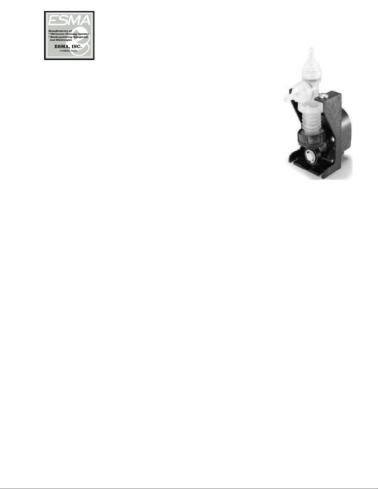
he Metering Pump is a Gorman-Rupp bellows metering pump.
The supplied inlet tube from the metering pump should be
inserted into a gallon jug of Esma cleaning solution concentrate.
The pump is configured to “meter” a 1% concentrate during the
fill cycle, approximately 180ml. Please use only proper detergent
which is formulated for use with the E789 model.
PLEASE READ THESE INSTRUCTIONS THOROUGHLY BE ORE
INSTALLATION AND OPERATION. CALL 800-276-2466 I YOU
HAVE ANY QUESTIONS
2. INS ALLA ION
If the control module is to be placed directly in front of tank, allow 5 inches
between counter opening and front of cabinet (diagram 1). Also, 28 inches of
clearance is necessary under the counter for drains.
Control Module - Cut opening of 4 ¼” x 10 ¼” in front of cabinet. The overall
flange of unit on front of cabinet is 5” x 12”, so center unit accordingly. Module
will be mounted later with 4, No. 8 wood screws.
ank Module - Cut opening of 18” x 11 ¼” in top of counter. The overall flange
of unit on top of counter is 20” x 13”, so center unit accordingly. Place tank in
opening and mark on counter the mounting studs welded under top plate.
Remove tank and drill mounting holes with1/4” drill bit. Do not mount tank
until control module opening is cut out.
ank Module should be set in counter first. A gasket is glued to the underside
of the top plate to prevent liquid from seeping into the counter. Place the tank-
mounting studs into the pre-drilled holes in counter and tighten down with 8 x
32 nuts and washers, which are supplied. (DO NOT OVERTIGHTEN).
Power Module measures 8’ x 16” x 18”D. However, 1” of clearance is necessary
both at the front and back of unit for proper ventilation. The electrical
connections, from tank and control modules, attached to the top of the module,
require additional 2 to 3 inches of space.
he Metering Pump should be monitored to assure that there is solution in
the jug. Due to the length of tubing, it will take one cycle for the metering
pump to become “primed”. Once the pump is primed, a 1% solution
concentrate will automatically be added to the water during the fill cycle.
Please regularly check to make sure that there is adequate cleaning solution in
the jug.

Celebrating over 30 years of excellence in manufacturing ultrasonic cleaning
equipment, electropolishing equipment and associated chemistries
ESMA, Inc.
P. O. BOX 734 * SOUTH HOLLAND, IL 60473 * (800)-276-2466 * AX (708)331-8919
5
3. PLUMBING HOOK-UP
A. Water Input (Diagrams 2 & 3, see last page)
The primary solenoid should be connected to a hot water source.
This solenoid has a ½” NPT female opening. A ½”MNPT x 3/4”MGH
adapter has been supplied for hot water hookup using a standard
washing machine water supply hose (not supplied). It is recommended
that a filter washer be installed into the water supply hose to prevent
sediment debris from entering solenoid from water source. The high-
pressure hose should connect the solenoid to a shut-off valve (not
supplied) at you water source. A flow regulator is incorporated into the
unit; therefore, the shut-off valve must not restrict the flow more than
3.5 GPM.
Also, a backflow regulator (not supplied) may have to be attached at your
water source to comply with local regulations.
B. Water Output (Diagram 2, see last page)
1½” x 16” elbow (A), which is supplied, is to be attached with a slip nut
(B) and washer (C) to the 1½” output nipple. (This piece can be hooked
up prior to installation of the tank but that is not necessary. The
tailpiece (D) with ¾” input (supplied) is to be attached to elbow (A) with a
slip nut (E) and adapting washer ( ). Attached to the tailpiece, with
a hose clamp (G), will be 2’ of ¾” hose (I). The other end of this hose is to
be attached to be attached to hose adapter (H), with the hose clamp (G),
after (H) is threaded into the drain solenoid using Teflon tape or joint
compound. A “P” trap (not supplied) is then to be attached to tailpiece
(D) prior to hookup to drain line.
4. ELEC RICAL
The unit is rated at 1500 W, 120 VAC, 50/60 HZ. Only the power module is
plugged into your 120VAC supply (diagram).
The Tank Module has two plugs. Both plugs are attached to power module at
receptacles C & E.
Control Module plug (M) plugs into power module receptacle (G).
Only the plug from power module (A) is to be connected to your power source.
Unit must be electrically grounded. The power cord must be connected to a
three-way grounded outlet. or 2-wire service, an adapter with external ground
wire is necessary. Connect the green grounding wire of the adapter to the

Celebrating over 30 years of excellence in manufacturing ultrasonic cleaning
equipment, electropolishing equipment and associated chemistries
ESMA, Inc.
P. O. BOX 734 * SOUTH HOLLAND, IL 60473 * (800)-276-2466 * AX (708)331-8919
6
screw, which holds the electric outlet plate cover to the socket. DO NOT
OPERATE UNIT WITHOUT PROPER GROUNDING. A fuse, 15AMP, 120VAC, is
located on the power module.
5. CON ROL FUNC ION
A. Main Switch: When unit is ready for operation, put the main
switch to ON and the indicator light on the power and the Control
Module will be ON.
B. Run-Stop Switch: Located on Control Module, must be in the RUN
position for the programmable controller to operate. If during the
program cycle you want to stop the process, turn switch to STOP position
and the program cycle will discontinue. Move switch back to RUN
position and program will START over at the beginning of the fill cycle
when start button is pushed.
Use run-stop switch only for emergency stopping of unit.
C. Fill/Clean/Full Cycle Switch:
Fill: When the ill cycle is selected and the START button is
pushed the tank will fill and hold with heated detergent. Use this cycle if
you do not have a full load of instruments and you would like to soak
them until ready to complete the cycle.
Clean: Select Clean cycle only after the fill step above has been
run. Pressing START when there is a full load of instruments will
complete the clean/rinse/dry cycle. You cannot start the clean cycle if
the fill cycle (above) is not completed first.
Full Cycle: When ull Cycle is selected and the START button is
pushed the unit will fill with heated detergent and continue
automatically with the clean/rinse/dry steps.
This is a safety precaution so the ultrasonics will not operate without any
liquid in the tank.

Celebrating over 30 years of excellence in manufacturing ultrasonic cleaning
equipment, electropolishing equipment and associated chemistries
ESMA, Inc.
P. O. BOX 734 * SOUTH HOLLAND, IL 60473 * (800)-276-2466 * AX (708)331-8919
7
6. PRELIMINARY S AR -UP
After plumbing is completed, conduct the following test to determine if there
are any leaks in the system.
A. Turn main power ON
B. RUN-STOP switch to ON
C. ILL/CLEAN switch to ILL
D. Close cover
Push START button and gradually open the inlet valve you installed in the
rinse line to bleed the air out of the line; them immediately open valve
completely. The unit has a flow control valve which allows 3.5GPM, so it is
important that the inlet valve doesn’t restrict the flow to less than 3.5GPM or
the fill time will have to be increased. After 90 seconds, the fill solenoid will
close, and the water will be up to the overflow drain opening. Possibly, the first
time the inlet valve was not manually opened fast enough to allow 3.5GPM for
the entire 90 seconds. To test the overflow-rinse line, leave ILL/CLEAN switch
on ILL and push the start button and water will flow into tank for additional
90 seconds. Now you can check your plumbing for leaks.
CAU ION: When conducting this leak test, make sure the power module is not
under the plumbing in order to avoid getting the electronics wet.
To test the drain plumbing, move ILL/CLEAN switch to CLEAN and push
START button to start the ultrasonic cleaning cycles (make sure fan inlet and
outlet of power module are not obstructed). The clean cycle will cavitate for 10
minutes before the tank will drain. The entire clean cycle and times are given
in the procedure section. You can stop the clean cycle at any time by turning
the RUN-STOP switch to STOP and the program will revert back to the
beginning of the ILL CYCLE.

Celebrating over 30 years of excellence in manufacturing ultrasonic cleaning
equipment, electropolishing equipment and associated chemistries
ESMA, Inc.
P. O. BOX 734 * SOUTH HOLLAND, IL 60473 * (800)-276-2466 * AX (708)331-8919
8
7. OPERA ION
The basic principle of operation is the enhancement and
acceleration of the cleaning action through ultrasonic
cavitations. Instruments, or parts to be cleaned, are
placed in the basket (or cassette racks) and lowered into
the tank.
NEVER PLACE PARTS DIRECTLY ON THE BOTTOM O THE TANK.
The baskets and cassette racks have rubber supports to keep parts off bottom
of tank.
8. PROCEDURE
1. Turn main power ON
2. Turn RUN-STOP switch to RUN. (Should remain in RUN position at all
times.
3. Set ILL/CLEAN switch to ILL.
4. Verify that the metering pump inlet supply is inserted into a gallon jug
of an approved Esma cleaning concentrate (see section on cleaning
agents).
5. Lower basket with instruments, or parts, on support rack.
6. Close cover.
7. Push START button and water will enter the tank for 90 seconds.
8. At this point more instruments (or parts) could be added when
available, or move ILL/CLEAN switch to CLEAN, push START button
and the cleaning program will automatically proceed through the cycle
as follows:

Celebrating over 30 years of excellence in manufacturing ultrasonic cleaning
equipment, electropolishing equipment and associated chemistries
ESMA, Inc.
P. O. BOX 734 * SOUTH HOLLAND, IL 60473 * (800)-276-2466 * AX (708)331-8919
9
E789 UNI
Function ime/Seconds
1. ill with hot water and Detergent concentrate 60
2. ill with hot water only 30
3. Ultrasonic cleaning 600
4. Drain 180
5. ill 90
6. Ultrasonic 60
7. Ultrasonic/Rinse 60
8. Ultrasonic 60
9. Ultrasonic/Rinse 60
10. Ultrasonic 60
11. Drain 150
12. Drain, Dryer, an 420
13. Drain, an 120
14. Buzzer 5
TOTAL 1835 seconds
(30 ½ minutes)
9. WA ER CONSUMP ION
In the program, 5 gallons of water are used on the initial fill cycle with an
additional 12 gallons used in the fill-rinse steps, C to H, for a total of 17 gallons
of hot water used per cycle.
If any changes in the rinse programs are required, consult the manufacturer.
10. DRYING
Incoming air is heated in the tank cover to 160° and forced by the fan
through the tank chamber before exhausting through the tank cover.
CAUTION: Do not touch the cover during the drying cycle because some areas
will be hot. Also, NEVER place any towel or obstruction over the fan intake on
cover. After 7 minutes of hot air drying, the parts are left in the tank for 2
minutes to allow some cooling to take place before handling. The air
temperature during the hot air drying can be increased or decreased by
adjusting a thermo-switch located in dryer cover at hot air exit. Please contact
manufacturer for more details.

Celebrating over 30 years of excellence in manufacturing ultrasonic cleaning
equipment, electropolishing equipment and associated chemistries
ESMA, Inc.
P. O. BOX 734 * SOUTH HOLLAND, IL 60473 * (800)-276-2466 * AX (708)331-8919
10
11. PRESOAKING OF INS RUMEN S
or maximum effective cleaning, it is best if blood and other substances do not
dry on the instruments. Therefore, fill the tank with hot water and cleaning
agent and use the tank as a holding vessel for instruments until enough have
accumulated to warrant cleaning.
12. CLEANING AGEN
Use only Esma brand detergent concentrates when operating the E789
with metering pump. Esma produces 3 powerful liquid cleaning agents:
•Esma-Shine E105
•Esma-General Purpose E589
•Esma-Zyme E1240.
DO NOT use powdered detergents; some powders take too long to go into
solution. The metering pump is engineered to pump only the correct amount of
detergent concentrate into the tank during the fill cycle. Esma brand
detergents are formulated to meet the pump ratios. The metering pump has
been factory calibrated to meter in 180ml of detergent concentrate during the
fill cycle. By not using the correct cleaning agent problem can arise with final
rinsing of parts if too much suds are generated.
13. LOW LEVEL SENSOR
A low-level safety device is installed on the tank module to assure that the
ultrasonics will not come on if there is less than three inches of water in the
tank. A stainless probe is fixed in a Teflon plug mounted on the tank wall.
When the liquid in the tank covers the probe the ultrasonics will activate
during the clean or rinse cycles. Periodically, the probe should be wiped off to
prevent insulating residues from cleaning agents, etc. from accumulating.
14. PROGRAMMABLE CON ROLLER
An Omron CPM-20CDR programmable controller (PLC) is used to control the
ILL and CLEANING process. A peripheral device (C200h-PRO27-E) is available
to change the program or modify the times of the process. The memory
protection maintains the program during power interruptions and a flash
memory backup will save the program for 20 days at an ambient temperature
of 77°. PLC status indicators, located on top of the PLC, show the operating
status according to the following table:
Celebrating over 30 years of excellence in manufacturing ultrasonic cleaning
equipment, electropolishing equipment and associated chemistries
ESMA, Inc.
P. O. BOX 734 * SOUTH HOLLAND, IL 60473 * (800)-276-2466 * AX (708)331-8919
11
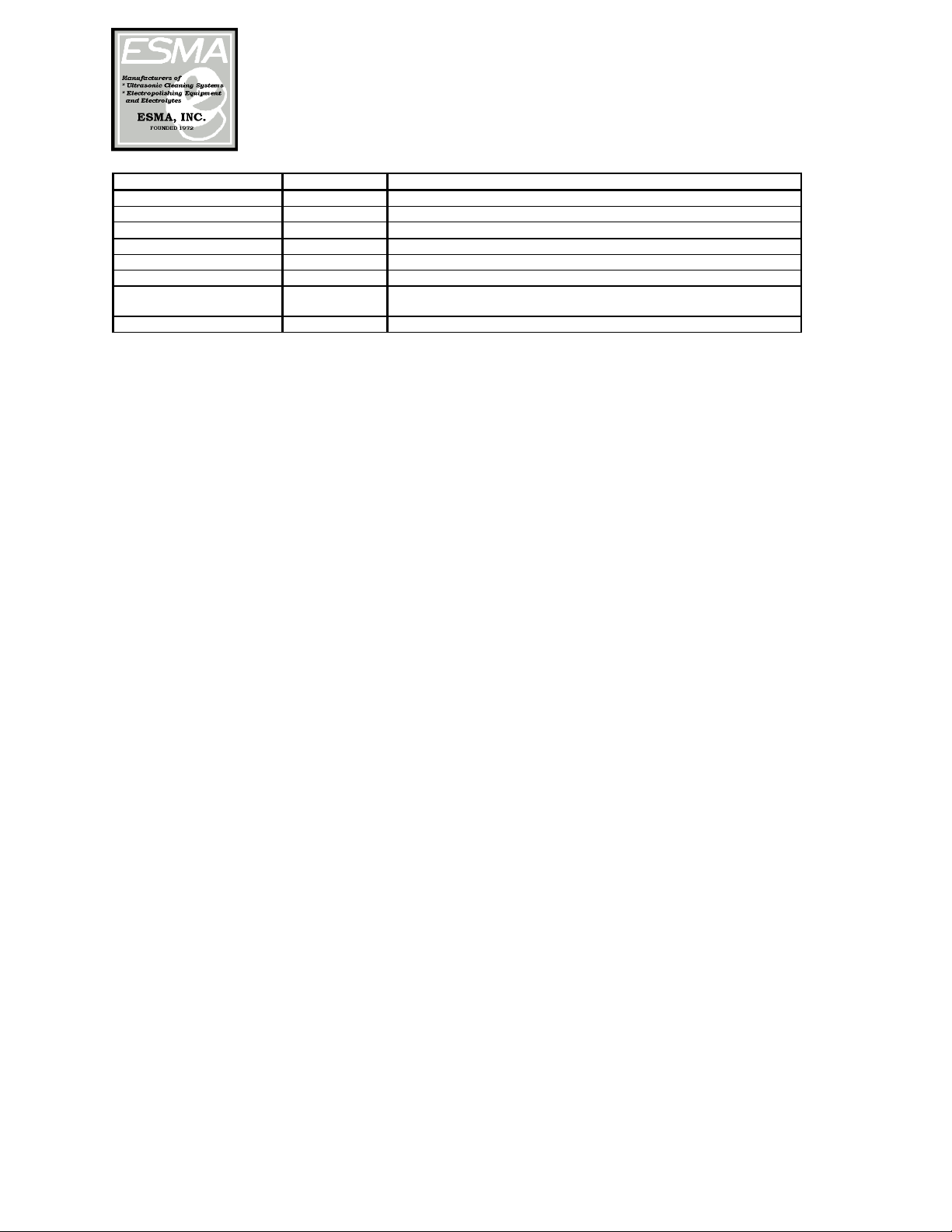
Indicator Status Meaning
POWER (green) ON Power is being supplied to the PLC.
OFF Power isn’t being supplied to the PLC.
RUN (green) ON The PLC is operating in RUN or MONITOR mode.
OFF The PLC is in PROGRAM mode or a fatal error has occurred.
ERROR/ALARM (red) ON A fatal error has occurred. (PLC operation stops.)
FLASHING A non-fatal error has occurred. (PLC operation continues.)
COMM (orange)
ON Data is being transferred via the Peripheral Port.
OFF Data isn’t being transferred via the Peripheral Port.
15. MAIN ENANCE
Periodically, the drain screen in tank will have to be removed and cleaned. The
accumulated lint and debris could slow down the draining enough so tank will
not be emptied of cleaning solution when rinse cycle begins.
Once a month, open power module and vacuum any dust that might have been
drawn in by the fan. Never operate unit with cover of power module off.
The tank is manufactured of 316SS and the modules of 304SS. Clean with a
commercially available cleaner for stainless steel kitchen appliances.
OR ASSISTANCE CALL 800-276-2466 or 708-331-1855
16. ROUBLE SHOO ING
•If there seems to be erratic behavior with a component, or if the fill
and/or clean cycle seem to have changed, always go through the
following procedure:
oTurn RUN-STOP switch momentarily to STOP and then back to
RUN. The program will now clear and revert to the beginning
calling for a ILL CYCLE. Move ILL-CLEAN switch to ILL and
push START regardless of if the tank has water in it.
oIf the problem persists, continue with trouble shooting or call
manufacturer.
•If there is still a problem, look at the PLC located in the Power module.
With MAIN switch ON and RUN-STOP in RUN position. Make sure that
the POWER and RUN lights are ON.
Celebrating over 30 years of excellence in manufacturing ultrasonic cleaning
equipment, electropolishing equipment and associated chemistries
ESMA, Inc.
P. O. BOX 734 * SOUTH HOLLAND, IL 60473 * (800)-276-2466 * AX (708)331-8919
12
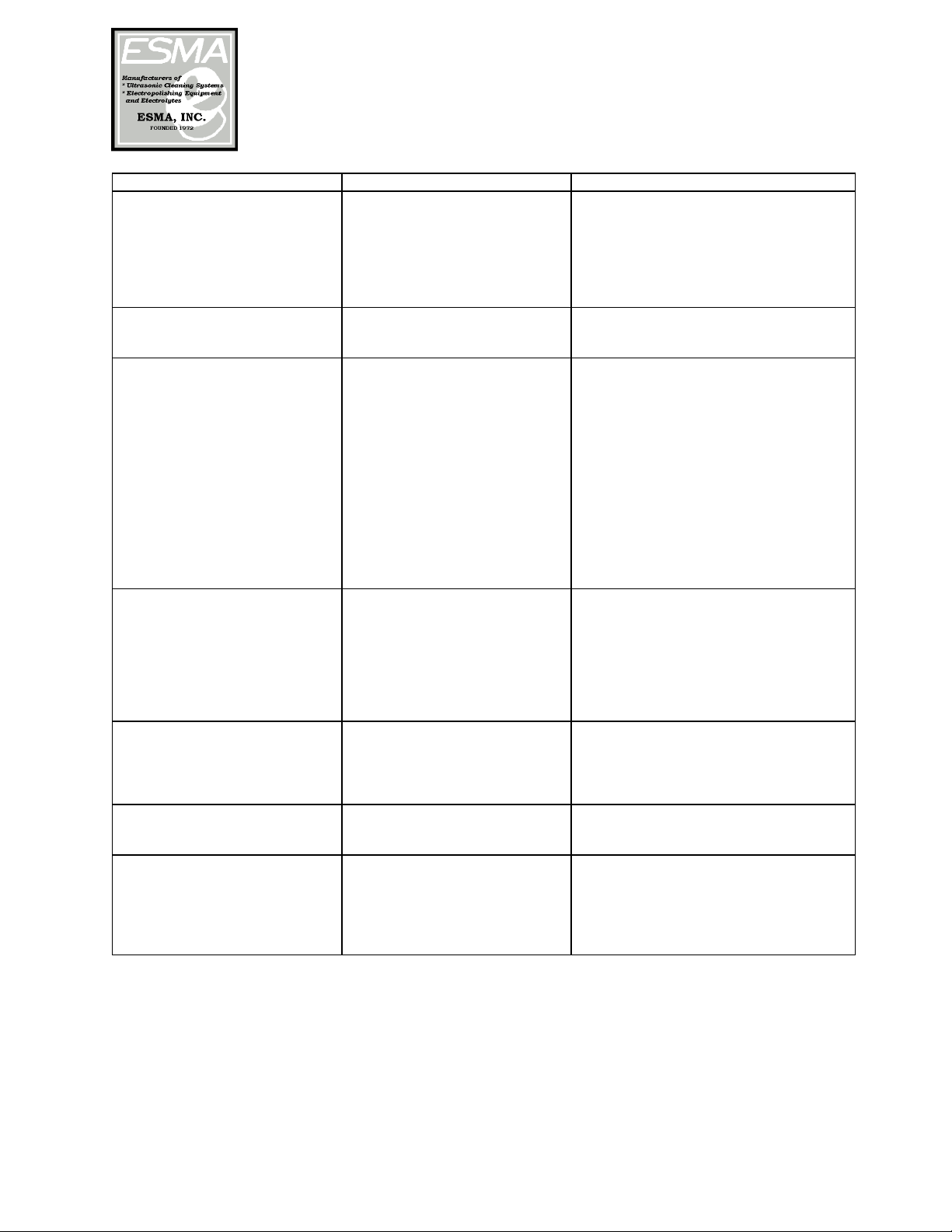
PROBLEM CAUSE REMEDY
Rinse solenoid is noisy,
pulsating and little or no water
coming into tank when output
00 is ON
Particles or other
accumulation has entered
bleed line of solenoid
Low water pressure
Solenoid needs to be cleaned out (see
instruction sheet for fill solenoid)
Make sure filter screen is in place
prior to valve
5-10 PSI water pressure is required to
operate solenoid
No ultrasonics when output 01
is ON. Large cooling fan in
power module is ON.
use blown on circuit boards. Need repair—check that cooling fan is
operating during cleaning.
No ultrasonics when large
cooling fan is O when
output 01 is on
Low water level in tank has
activated low level safety
control
Rise solenoid problem, or
insufficient water supply.
In line fuse to PLC is blown.
Relay for fan and circuit
boards not working.
Low-level safety control is
faulty.
As above (fill solenoid problem)
Replace 1.5Amp/120V fuse
Replace relay
Clean deposit off probe
Contact manufacturer
Dryer gets too hot an inlet on top off cover is
blocked
Thermostat inside cover needs
adjustment
Dryer an not working with
output 06 on
Remove obstacle
Contact manufacturer
Replace in-line fuse to PLC
Dryer is cool with output 03
ON
Thermostat needs adjustment
if there is some heat.
Relay in control module is
faulty
Contact manufacturer
Replace relay
Tank drains with output 02
O
Debris lodged in drain
solenoid
Clean out solenoid (see instructions)
and make sure drain screen in place
in tank
Tank does not drain with
output 0N
Drain screen clogged.
Y strainer clogged
Solenoid not operating
Clean and replace screen.
Clean out Y strainer
In-line fuse to PLC is blown or clean
out solenoid valve

Celebrating over 30 years of excellence in manufacturing ultrasonic cleaning
equipment, electropolishing equipment and associated chemistries
ESMA, Inc.
P. O. BOX 734 * SOUTH HOLLAND, IL 60473 * (800)-276-2466 * AX (708)331-8919
13
INSTALLATION INSTRUCTIONS & CABINET REQUIREMENTS OR
ULTRASONIC WASHER MODEL E789
1. INTRODUCTION
The units automatically perform a cleaning cycle, the major steps of which are:
• Ultrasonic cleaning
• Ultrasonic rinsing (hot tap water)
• Ultrasonic rinsing (deionized water)-unit E291 only • Hot air drying
The E789 unit has only one rinse solenoid (primary), which is connected to the hot tap water supply.
The result is a finished product ready for the next step (sterilizing, packaging, assembly, storage).
The unit consists of three sections: 1) ank Module-to be installed in the counter 2) Control Module-to
be installed in front of counter and 3) Power Module- to be installed under the counter.
he ank Module is manufactured from 316 stainless steel, with 12 potting transducers mounted on the
bottom. The tank is equipped with two fill solenoids (E789 has only one), a drain solenoid and a low level
control to prevent electronic damage if water pressure is lost. The tank is fitted with a 304 stainless
hinged cover housing the fan and heater for air-drying.
he Control Module is manufactured from 304 stainless and
contains the switches to start the ILL or CLEAN cycles and stop the process manually, if needed.
he Power Module contains the self-tuning modular circuit boards, programmable controller, high
velocity fan to cool the electronics and R I filter to eliminate high frequency noise. PLEASE READ THESE
INSTRUCTIONS THOROUGHLY BE ORE INSTALLATION AND OPERATION. CALL (800) 276-2466 I YOU
HAVE ANY QUESTIONS.
2. INSTALLATION
If the control module is to be placed directly in front of tank, allow 5 inches between counter opening and
front of cabinet (diagram 2). Also, 28 inches of clearance is necessary under the counter for drains.
Control Module-Cut opening of 4-1/4" x 10 1/4" in front of cabinet. The overall flange of unit on front of
cabinet is 5" x 12", so center unit accordingly. Module will be mounted later with 4 No. 8 wood screws.
ank Module-Cut opening of 18" x 11-1/4" in top of counter.
The overall flange of unit on top of counter is 20" x 13", so center unit accordingly. Place tank in opening
and mark on counter the mounting studs welded underneath top plate. Remove tank and drill mounting
holes with 1/4" drill bit. Do not mount tank until control module opening is cut out.
ank Module should be set in counter first. A gasket is glued to the underside of the top plate to prevent
liquid from seeping into the counter. Place the tank-mounting studs into the pre-drilled holes in counter
and tighten down with 8 x 32 nuts and washers, which are supplied. (DO NOT OVERTIGHTEN).
Power Module measures 8" x 16' x 18" D. However, I" clearance is necessary both at the front and back
of unit for proper ventilation. The electrical connections from tank and control modules, attached to the
top of the module, require additional 2 to 3 inches of space.
3. PLUMBING HOOK-UP
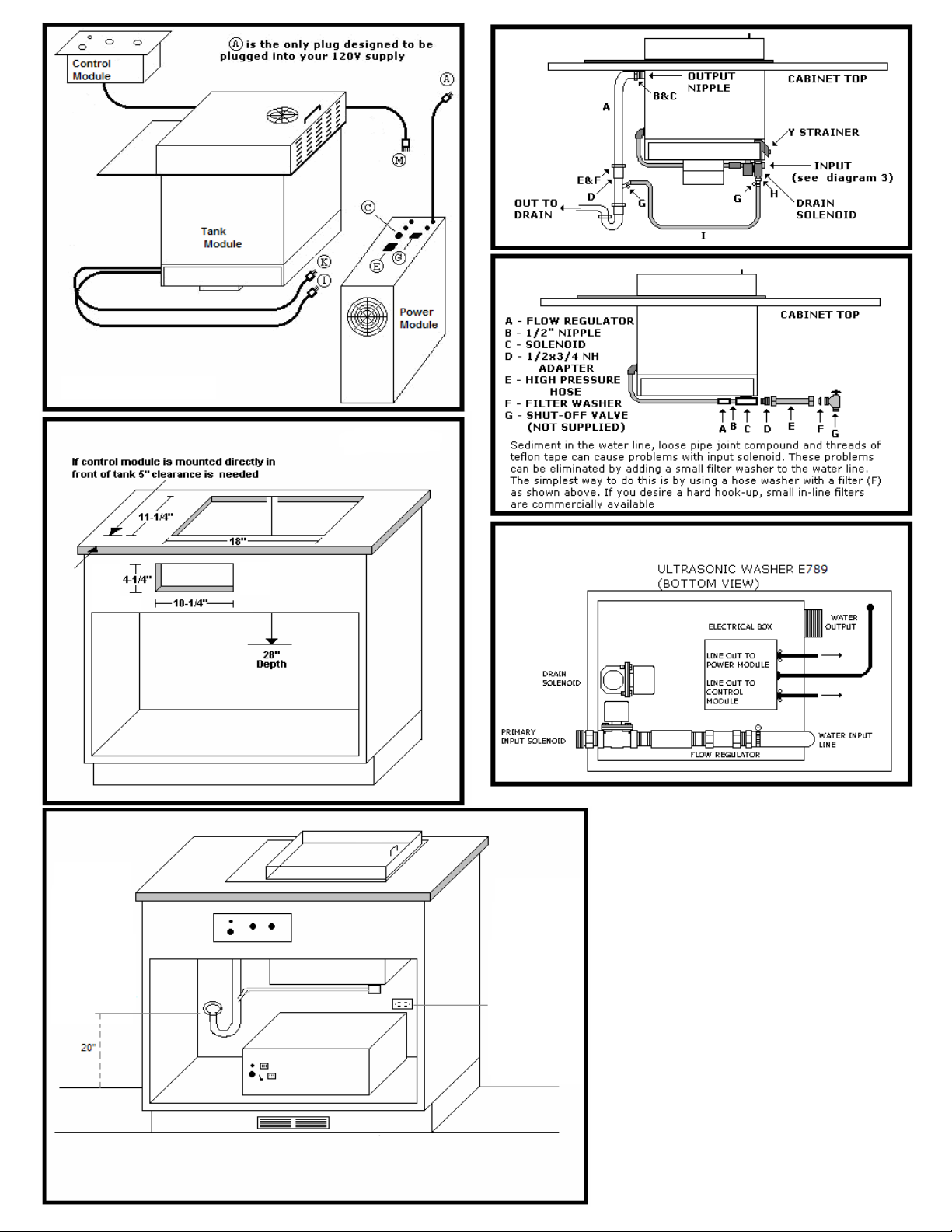
A. Water Input (Diagrams 3, 4 & 5, see last page)
The primary solenoid should be connected to a hot water source. This solenoid has a 1/2" NPT female
opening. An adapter and a high-pressure hose, with a filtered washer are supplied. The high-pressure
hose should connect the solenoid to a shut-off valve (not supplied) at your water source. A flow regulator
is incorporated into the unit, therefore, the shut-off valve must riot restrict the flow more than 3.5 GPM.
Also, a backflow regulator (not supplied) may have to be attached at your water source to comply with
local regulations. On Model E291 only, a deionized water source is connected to the secondary solenoid
following the instructions given for the primary solenoid (Diagram 5).
B. Water Output (Diagram 3
,
see last page)
1 1/2" x 16" elbow (A), which is supplied, is to be attached with a slip nut (B) and washer (C) to the 1 1/2"
output nipple. (This piece can be hooked up prior to installation of the tank but that is not necessary).
The tailpiece (D) with 3/4" input (supplied) is to be attached to elbow (A) with a slip nut (E) and an
adapting washer
( ). Attached to the tailpiece, with a hose clamp (G), will be 2' of 3/4 hose (1). The other end of this hose is
to be attached to hose adapter (H), with the hose clamp (G), after (H) is threaded into the drain solenoid
using Teflon tape or joint compound.

Celebrating over 30 years of excellence in manufacturing ultrasonic cleaning
equipment, electropolishing equipment and associated chemistries
ESMA, Inc.
P. O. BOX 734 * SOUTH HOLLAND, IL 60473 * (800)-276-2466 * AX (708)331-8919
14
A "P' trap (not supplied) is then to be attached to tailpiece (D) prior to hookup to drain line.
4. ELECTRICAL
The unit is rated at 1500 W, 120 VAC, 50/60 HZ. Only the power module is plugged into your 120 VAC supply
(diagram 4).
he ank Module has two plugs. Plug (K) goes to the under side of Control Module and attaches to receptacle (L).
Plug (1) is attached to power module at receptacle (E).
Control Module has two plugs, (M) and (N), which attach to receptacles (C) and (G) on the power module.
Only the plug from power module (A) is to be connected to your power source. Unit must be electrically grounded.
The power cord must be connected to a three-way grounded outlet. or 2- wire service, an adapter with external
ground wire is necessary. Connect the green grounding wire of the adapter to the screw, which holds the electric outlet
plate cover to the socket. DO NOT OPERATE UNIT WITHOUT PROPER GROUNDING. A fuse, 15 AMP 120 VAC, is
located on the power module.
Celebrating over 30 years of excellence in manufacturing ultrasonic cleaning
equipment, electropolishing equipment and associated chemistries
ESMA, Inc.
P. O. BOX 734 * SOUTH HOLLAND, IL 60473 * (800)-276-2466 * AX (708)331-8919
15
Standard
120 VAC
outlet can
be
located
anywhere
within 6 feet
of unit. Only
the plug from
the power
module will
plug into
outlet
Optimal
drain height
is 12” from
floor.
Maximum
height to be
no more
than 20”
from floor.
Diagram 1
Diagram 3
Diagram 4
Diagram 5
Diagram 2
Diagram 6

Celebrating over 30 years of excellence in manufacturing ultrasonic cleaning
equipment, electropolishing equipment and associated chemistries
ESMA, Inc.
P. O. BOX 734 * SOUTH HOLLAND, IL 60473 * (800)-276-2466 * AX (708)331-8919
16
ACCESSORIES
Included with your E789 Unit are the following accessories for installation.
1. ½” tubing to be inserted on the METERING PUMP barbed fitting and
secured with supplied hose clamps. This tube is to be inserted into a gallon
jug of detergent.
2. Brass fittings for INPUT valve and DRAIN SOLENOID
3. PVC Waste Arm. Connects to OUTPUT NIPPLE in
4. Branch Tailpiece. Connects to waste arm (3) and tubing connects to DRAIN
SOLENOID brass fitting
5. Overflow drain screen
6. Control Module mounting screws
7. Tank mounting screws
Table of contents
Other Esma Washer manuals


