Esma E992 User manual

Celebrating over 30 years of excellence in manufacturing ultrasonic cleaning
equipment, electropolishing equipment and associated chemistries
ESMA, Inc.
P. O. BOX 734 * SOUTH HOLLAND, IL 60473 * (800)-276-2466 * AX (708)331-8919
Page
1

Celebrating over 30 years of excellence in manufacturing ultrasonic cleaning
equipment, electropolishing equipment and associated chemistries
ESMA, Inc.
P. O. BOX 734 * SOUTH HOLLAND, IL 60473 * (800)-276-2466 * AX (708)331-8919
Page
2

Celebrating over 30 years of excellence in manufacturing ultrasonic cleaning
equipment, electropolishing equipment and associated chemistries
ESMA, Inc.
P. O. BOX 734 * SOUTH HOLLAND, IL 60473 * (800)-276-2466 * AX (708)331-8919
Page
3
Esma Inc.
PO Box 734 450 W. Taft Drive
South Holland, IL 60473
708-331-1855 800-276-2466 FAX 708-331-8919
Instructions for
Model E992 Passivation
Ultrasonic Washer
Introduction
The Model E992 ultrasonic washer is equipped with three, 30 gallon heated storage
tanks (HST) for alkaline cleaning solution, citric acid or nitric acid solution and
rinse water. Pump filter systems are also incorporated into the HST’s. The
complete system also uses fresh DI water for a final rinse cycle.
The unit is housed in a 304 stainless steel console. The tank is manufactured from
SS 316 with 36 double potting transducers mounted on the bottom. The tank is
fitted with a SS hinged cover, which houses the fans and heaters for air drying.
Inside the console there are 2 Power Module boxes (generators) and the drain
pumps. The Power Modules contain the self-tuning modular circuit boards, high
velocity fans to cool the electronics, and RFI filters to eliminate any high
frequency interference. A control box is mounted on the rear of the console unit
and contains the programmable controller and other related components.
A Beijer HMI panel mount interface is included with the unit allowing monitoring
of the on-line operation and modifying of the program, as well as data collection of
the passivation process.
PLEASE READ THESE INSTRUCTIONS THOROUGHLY BEFORE
INSTALLATION AND OPERATION. CALL (800) 276-2466 IF YOU HAVE
ANY QUESTIONS.

Celebrating over 30 years of excellence in manufacturing ultrasonic cleaning
equipment, electropolishing equipment and associated chemistries
ESMA, Inc.
P. O. BOX 734 * SOUTH HOLLAND, IL 60473 * (800)-276-2466 * AX (708)331-8919
Page
4
Installation
When unit is removed from skid, the supplied casters must be installed on the
bottom of unit. Place casters with locking brakes on front corners of unit.
The unit has been thoroughly bench-tested and is shipped to the customer ready to
operate. Move the unit into position and lock Caster wheels. Once the position of
the unit has been established, the electrical and plumbing requirements must be
completed by the user.
The power modules inside the unit have been bolted to the bottom of chassis for
shipping. They can remain bolted. However, if either has to be removed for any
reason, the filter screen door on the back of the unit has to be opened. Once the
filter is removed, the screws and bolts (2’’ in each bracket) in hold-down brackets
can be removed. These need not be replaced for normal use and movement of unit.
Leave hold-down bracket fixed to power modules.
Electrical
The E992 unit is wired for 230 VAC. The rating is 9500 watts, single phase
Each Heated Storage Tank (HST) is rated for 1,650 watts(included above),
120VAC, 50/60HZ and is supplied with a cord with a NEMA 5-15 plug. A 15
amp, 125 volt fuse is located underneath the control box. The power cords are
intended to be plugged into the master electrical panel located on the left side of
the E992 unit. The system is designed to be wired at this panel. An electrical
diagram is located inside the panel door and also as an attachment to this manual.
DO NOT OPERATE UNIT WITHOUT PROPER GROUNDING.
Each heated storage tank (HST) has a separate communication cord with an
amphenol connector to be connected to the sockets at the rear of the washer as
follows:

Celebrating over 30 years of excellence in manufacturing ultrasonic cleaning
equipment, electropolishing equipment and associated chemistries
ESMA, Inc.
P. O. BOX 734 * SOUTH HOLLAND, IL 60473 * (800)-276-2466 * AX (708)331-8919
Page
5
Top Left – HST 4 (FUTURE Acid Tank)
Top Right – HST 1 (Clean Storage Tank)
Bottom Right – HST 2 (Rinse Storage Tank)
Bottom Left – HST 3 (Acid Storage Tank)
IMPORTANT TO MATCH THE PLUGS AND
RECEPLACLES OF THE TANKS.
Plumbing Hook-Up
When the system was wrapped up for shipping the hoses which were used in
testing were included and marked. In the event that the tanks are to be located in a
different orientation than was configured in the plant, additional hose will need to
be procured. If the system is set up with HST-1 thru 3 on the right of the washer
the process should be straight-forward (as illustrated, use markings on the included
hoses for connections), setup should be as illustrated below.
Clean
Rinse
Acid
(HST1) (HST2) (HST3)

Celebrating over 30 years of excellence in manufacturing ultrasonic cleaning
equipment, electropolishing equipment and associated chemistries
ESMA, Inc.
P. O. BOX 734 * SOUTH HOLLAND, IL 60473 * (800)-276-2466 * AX (708)331-8919
Page
6
** IMPORTANT ** The city sewer line S10 MUST BE VENTED. If you are
plumbing to an overhead drain, you must plumb to a basin and sump pump so that
the system drain pump does not get air-locked during the program.
FOR ASSISTANCE CALL: 800-276-2466.
•
Solenoid 1 is to be
connected to your
pressurized in-house DI
water supply.
FUTURE CONNECTION
•Connect hose from
Solenoid 9 on HST 4, the
FUTURE Acid Storage
Tank
•Connect hose from the
S7 on the Acid Storage
tank to this fitting.
•Connect hose from the
S5 on the Rinse Storage
tank to this fitting.
•Connect hose from the
S3 on the Clean storage
tank to this fitting
•
Connect hose from Solenoid
“S10” to a vented drain if
needed.
•FUTURE CONNECTION
Connect hose from Solenoid 8 to
the filter chamber on HST 4, the
FUTURE Acid Storage Tank.
•Connect Solenoid “S6” to the
filter chamber on HST 3, the
Acid Storage Tank.
•Connect hose from Solenoid 4 to
the filter chamber on HST 2, the
Rinse Storage Tank.
•Connect hose from Solenoid 2 to
the filter chamber on HST 1, the
Clean Storage Tank
Solenoid Manifold
Rear of E992 Unit

Celebrating over 30 years of excellence in manufacturing ultrasonic cleaning
equipment, electropolishing equipment and associated chemistries
ESMA, Inc.
P. O. BOX 734 * SOUTH HOLLAND, IL 60473 * (800)-276-2466 * AX (708)331-8919
Page
7
The following plumbing connections should be made: (See flow diagram above)

Celebrating over 30 years of excellence in manufacturing ultrasonic cleaning
equipment, electropolishing equipment and associated chemistries
ESMA, Inc.
P. O. BOX 734 * SOUTH HOLLAND, IL 60473 * (800)-276-2466 * AX (708)331-8919
Page
8
E992
Solenoid 1 “S1” connects (inlet) to the in house pressurized DI water source.
Solenoid 10 “S10” connects (outlet) to your sewer or in house drain. ** IMPORTANT
** the drain line MUST BE VENTED. If you are plumbing to an overhead drain, you
must plumb to a basin and sump pump so that the system drain pump does not get air-
locked during the program. (Drain hose NOT supplied). FOR ASSISTANCE CALL:
800-276-2466
HST1 (Clean)
Solenoid 3 “S3” on the Clean Storage tank connect to bottom inlet fitting on the E992
unit.
A manual ball valve is to be used to empty the storage tank and a high level float switch
is included to prevent overflow.
The inlet port on the 10” filter has a 3/4” barbed fittings. Connect to Solenoid 2 “S2” on
the E992 unit.
HST2 (Rinse) (Unit has 2 filter chambers)
Solenoid 5 “S5” on rinse tank should connect to the middle inlet fitting on the E992 unit.
A manual ball valve is to be used to empty the rinse storage tank.
A manual ball valve is to be used to empty the storage tank and a high level float switch
is included to prevent overflow.
The inlet port on the filter has a 3/4” barbed fittings. Connect to Solenoid 6 “S6” on the
E992 unit.
The Rinse Storage has a 20” filter chamber and a 10” filter chamber. The 20” filter
should be already be connected to Solenoid 21 “S21” for recirculation (See Below). The
10” filter chamber has a 3/4” barbed fittings. Connect to Solenoid 4 “S4” on the E992.
HST3 (Acid)
Solenoid 3 “S3” on the Clean Storage tank connect to bottom inlet fitting on the E992
unit.
A manual ball valve is to be used to empty the storage tank.
A manual ball valve is to be used to empty the storage tank and a high level float switch
is included to prevent overflow.
The inlet port on the 10” filter has a 3/4” barbed fittings. Connect to Solenoid 6 “S6” on
the E992 unit.
Each storage tank is supplied with manual ball valves to drain the tanks when necessary.

Celebrating over 30 years of excellence in manufacturing ultrasonic cleaning
equipment, electropolishing equipment and associated chemistries
ESMA, Inc.
P. O. BOX 734 * SOUTH HOLLAND, IL 60473 * (800)-276-2466 * AX (708)331-8919
Page
9
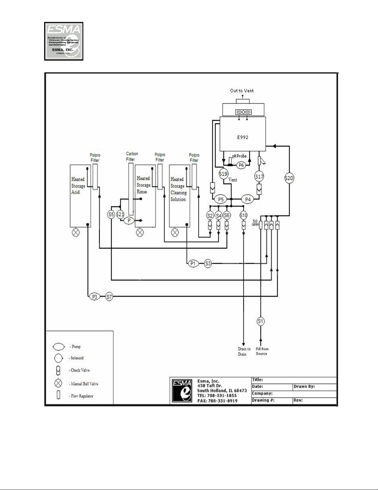
Heated Storage Tanks (HST)
After plumbing is completed, fill storage tanks with
appropriate solution. The 30 gallon storage tanks are double
walled insulated. Each tank has 1,400 watts of heat applied to
the bottom of tank controlled by digital temperature controllers
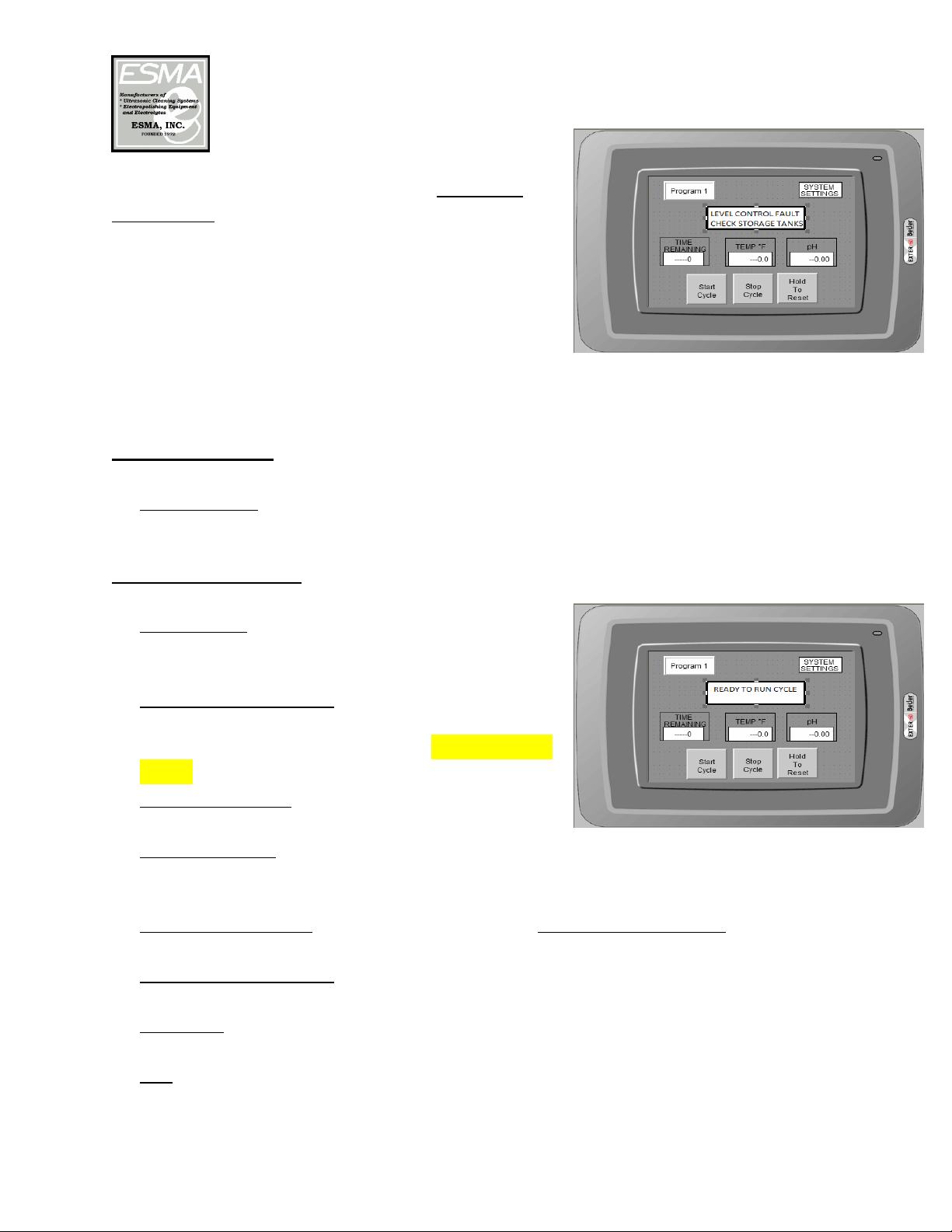
(instructions included) located on the control box. Turn ON the
temperature control and set to the desired temperature (factory
preset to 120°F). Press the MD button and wait for 2 seconds
for current set point to display. The temperature setting can be
changed using the arrow keys. Pressing MD again will return
the controller to run mode. Refer to the product description
sheets of the chemistry for appropriate temperatures. If tank is
full, the liquid heat-up rate is 30°F/hour. Because of the
double wall insulated tank the overnight cool down is minimized if the tank is
covered. A float switch in the tank will turn the heaters off in the event that the
liquid level is too low.
DO NOT TURN HEATERS ON WITHOUT WATER IN STORAGE TANK.
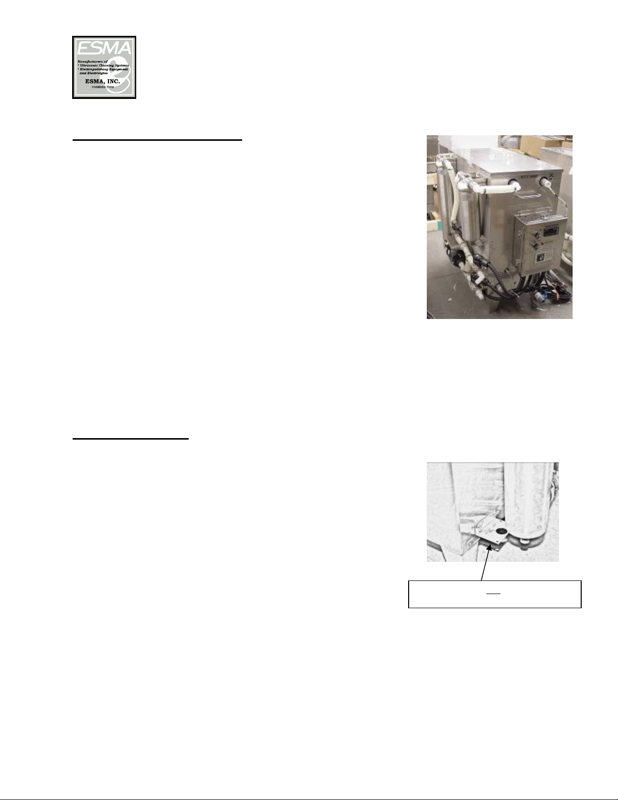
Pump Filter System
Each storage tank is equipped with a filter system with a 10”
SS chamber. The rinse storage is also equipped with a 20” SS
chamber. This provides for continual filtration of the rinse
water and is controlled by a switch on the control box marked
“RECIRCULATE PUMP”. When the switch is on, the rinse
water will recirculate through the 20” carbon filter for water
purification. This recirculation can be turned off at any time.
If turned off then only the 10” filter will be used for
filtration when rinse water is returned to the storage tank
from the E992 unit.
Filter cartridges can be reordered as follows:
20” Carbon Filters - Part# 50J
10” Carbon Filters – Part# 50I
10” Polo-Pro Filters – Part# 50K Periodically the filter cartridges in the chambers of
the storage systems need to be changed. The filter chambers are higher than the liquid
level of the storage units so the liquid does not need to be drained to change the
cartridges.
Shipping bracket can be removed

Celebrating over 30 years of excellence in manufacturing ultrasonic cleaning
equipment, electropolishing equipment and associated chemistries
ESMA, Inc.
P. O. BOX 734 * SOUTH HOLLAND, IL 60473 * (800)-276-2466 * AX (708)331-8919
Page
10
Each storage tank is equipped with a high level
float switch. If the fluid level rises too high, the
float will trigger a system halt indicated on the
HMI (see picture at right). This will indicate that
there is a problem in the system which needs to be
addressed. If the float is reset, pressing START
will resume the program.
Control Function
1. Main Switch: When unit is ready for operation, turn the main switch to ON and
the Interface screen will display “Ready to Run Cycle”.
HMI Display Screen
2. PROGRAM: Pressing this button will open a
drop down menu to select a program. (see
below)
3. SYSTEM SETTINGS: Pressing this button
will open a numeric input pad for password
protection of all the cycle times. The password
is 450
4. START CYCLE: Press the start button to begin
any process.
5. STOP CYCLE: Pressing this button will pause the cycle. Pressing START
CYCLE again will resume the cycle at the same step; however, the timer for
that step will be reset.
6. HOLD TO RESET: Pressing this button and holding for 2 seconds will reset
system. (Button will blink to indicate a reset)
7. TIME REMAINING: This is a display only item and indicates the time
remaining for the current step.
8. TEMP °F: Indicates current temperature of the bath. Temperature settings can
be set in the SYSTEM SETTINGS.
9. pH: Indicated the current pH reading by the probe. pH settings can be set in
the SYSTEM SETTINGS.

Celebrating over 30 years of excellence in manufacturing ultrasonic cleaning
equipment, electropolishing equipment and associated chemistries
ESMA, Inc.
P. O. BOX 734 * SOUTH HOLLAND, IL 60473 * (800)-276-2466 * AX (708)331-8919
Page
11
Operation
Assuming the storage tanks and filters are filled and heated, the units can be placed
through its initial run. With the MAIN ON and PROGRAM 1 selected, pressing
the START CYCLE button will run a program cycle as shown in the following
table: (Use this grid to record time settings)
Plc
Step
Action
R3 Fill from Clean Tank
R4 Ultrasonic cleaning
R6 Drain to Clean Tank
R8 Fill from Rinse Storage Tank
R9 Ultrasonic rinse cascade to Rinse Storage Tank
R10 Ultrasonics rinse
R12 Drain to Rinse Storage Tank
R14 Fill from HST 3 (or 4) Acid Storage Tank
R15 Ultrasonic passivation
R16 Passivation - NO ultrasonics
R17 Drain to HST 3 (or 4) Acid Storage
R21 Fill from Rinse Storage Tank
R22 Ultrasonic rinse
R24 Ultrasonic rinse cascade to Rinse Storage Tank
R25 Drain to Rinse Storage Tank
R26 Fill from source
R27 Ultrasonic rinse overflowto Drain
R28 Ultrasonics rinse
R30 Drain to Drain
R31 Dry
R32 Dry with drain pump (20-30 seconds only)
R33 Dry
R34 Cool Down
R35 Alarm
Prog2 Prog3
ProgramTimes (seconds)
Prog1

Celebrating over 30 years of excellence in manufacturing ultrasonic cleaning
equipment, electropolishing equipment and associated chemistries
ESMA, Inc.
P. O. BOX 734 * SOUTH HOLLAND, IL 60473 * (800)-276-2466 * AX (708)331-8919
Page
12
To access the cycle time settings, select the program to be changed and press the
“System Settings” button on the top of the HMI interface. A password screen will
open. Your password to access this section is “450”. Use the subsequent screens
to make any necessary changes to the times of each cycle. Be aware that fill and
drain times should remain constant. This will assure that the same amount of rinse
water is drained and then re-filled into the Rinse Storage Tank. By pressing the
NEXT screen you will advance to subsequent screens.
A description of each step is as follows:

Celebrating over 30 years of excellence in manufacturing ultrasonic cleaning
equipment, electropolishing equipment and associated chemistries
ESMA, Inc.
P. O. BOX 734 * SOUTH HOLLAND, IL 60473 * (800)-276-2466 * AX (708)331-8919
Page
13
pH Meter
A Signet pH meter has been mounted on the panel
for displaying the current pH and temperature of
the tank bath. The program pH meter is tied to the
program with user defined pH limits. If a reading
falls out of limit, the system will stop running and
the HMI interface will read pH error. At this point
the operator will need to manually add solution to
the tank to adjust the pH, or change the limits in
the system. Pressing the start button will resume
the program.
Programmable Controller
An IDEC programmable controller is used to control the process. The unit has a
flash memory backup without a battery. The controller has indicator lights for
inputs and outputs which are lit during process. The system is also equipped with
a Beijer, EXTER model touchscreen interface. The interface allows for data
collection of the passivation process. The following data is collected and stored on
the interface:
Clean time
Clean temp
Clean ph
Rinse time
Rinse temp
Rinse pH
Acid time
Acid temp
Acid pH
Final Rinse time
Final Rinse temp
Final Rinse ph
Dry time
Total cycle time

Celebrating over 30 years of excellence in manufacturing ultrasonic cleaning
equipment, electropolishing equipment and associated chemistries
ESMA, Inc.
P. O. BOX 734 * SOUTH HOLLAND, IL 60473 * (800)-276-2466 * AX (708)331-8919
Page
14
The control box on the rear of the E992 unit has an Ethernet port
for connection to a data collection server (See photo above). An
FTP protocol will need to be used to collect the data.
IP address: 192.168.1.1, Subnet mask: 255.255.255.0
The raw data is comma delimited.
High and low Level Control
The tank has a high level sensor and a low level
sensor located in the tank wall. The high level
control will shut the main input solenoid S20 if the
solution level gets to high in the tank.
A low level sensor in the tank wall is located
approximately 3” from the bottom of the tank.
This sensor will send a signal to the PLC to halt
the program if tripped. The adjacent message will
appear on the interface in the event that this sensor
is tripped, indicating that not enough fluid was pumped into the tank:
Drying
In the drying portion of the programs, the incoming air is heated in the tank cover
to 160-180°F and forced by the fan through the tank cover. CAUTION: Do not
touch the cover during the drying cycle because some areas of the cover will be
hot.
Drying time will vary depending on the number of parts to be dried, if hot or cold
water was used to rinse parts before drying and if the cover is closed. Generally
parts should be dry in 7- 10 minutes.

Celebrating over 30 years of excellence in manufacturing ultrasonic cleaning
equipment, electropolishing equipment and associated chemistries
ESMA, Inc.
P. O. BOX 734 * SOUTH HOLLAND, IL 60473 * (800)-276-2466 * AX (708)331-8919
Page
15
NEVER place any towel or obstruction over the fan intake on cover. The air
temperature during Hot Air Drying can be increased or decreased by adjusting two
thermo-switches located in cover at hot air exit. The thermo-switches are adjusted
as shown below.
1. Disconnect unit from 120VAC and 230VAC supplies.
2. Remove top plate of dryer cover.
3. Thermostat is located in front of heater.
4. See drawing 1. Turn control knob slightly counter-clockwise to
decrease temperature.
5. Replace top plate and check air temperature. Repeat steps 1-4 if
not satisfactory.
Maintenance
1. Filters-Periodically the filter cartridges need to be changed as describe in a
previous section.
2. Drain Screens-Y strainers are located in the drain and overflow lines.
Periodically the drain screen in these strainers located under the tank inside the
unit will have to be removed and cleaned. Accumulated lint and debris could
slow down the draining, resulting in the incomplete removal of cleaning
solution before the rinse cycle starts.
The tank and modules are manufactured of 316 and 304 stainless steel. Clean with
a commercially available cleaner for stainless kitchen appliances.
Power Modules
The power modules contain the circuit boards, programmable controller, fans,
relays, RFI filters etc. There are 6 lights, one per circuit board to indicate if circuit
boards are operating. To check if all circuit boards are operating, open door
slightly when unit is ultrasonically cleaning; all indicator lights must be ON. If a
light is out, the corresponding circuit board will have to be repaired.

Celebrating over 30 years of excellence in manufacturing ultrasonic cleaning
equipment, electropolishing equipment and associated chemistries
ESMA, Inc.
P. O. BOX 734 * SOUTH HOLLAND, IL 60473 * (800)-276-2466 * AX (708)331-8919
Page
16
Cleaning of Solenoids
A periodic cleaning of all solenoid valves is desirable. The time between cleanings
will vary, depending on media and service conditions. In general, if the voltage to
the coil is correct, sluggish valve operation, excessive leakage, or noise indicate
that cleaning is required. A bulletin with maintenance instructions is enclosed.
FOR ASSISTANCE CALL: 800-276-2466
WARRANTY: Unit has one year guarantee, circuit boards two years and
transducer bonds and tank weld seams a lifetime guarantee.

Celebrating over 30 years of excellence in manufacturing ultrasonic cleaning
equipment, electropolishing equipment and associated chemistries
ESMA, Inc.
P. O. BOX 734 * SOUTH HOLLAND, IL 60473 * (800)-276-2466 * AX (708)331-8919
Page
17
This manual suits for next models
1
Other Esma Washer manuals
Popular Washer manuals by other brands

LG
LG T1166TEFTU Service manual

Electrolux
Electrolux EWS 86110W user manual

Alliance Laundry Systems
Alliance Laundry Systems AR105M X CONTROL Installation operation & maintenance

Galaxy
Galaxy 11017122700 Use & care guide

Klarstein
Klarstein 10028310 manual

Danube
Danube DD8 Instructions for installation, use and maintenance