Esmach SPI 160 A Hybrid Specification sheet

Instruction for use and maintenance
Notice d’utilisation et de maintenance
Istruzioni uso e manutenzione
SPIRAL MIXER WITH REMOVABLE BOWL
PETRIN A SPIRALE A CUVE FIXE
IMPASTATRICE A SPIRALE A VASCA ESTRAIBILE
SPI 160-300 A
HYBRID

! "
#$%$ "
&$$' "
&()*+,)--+)
"(.,))-/),.0
&(.1
" 2
$#34#$5&! &'
6$3$7'#'"#$&&!6$!
'7 #8$ $&4#3$&' $5 &'
53#'"#$&''&!6$!
#$&&&86&6$359 &'
$8$&56&&##'3&$6$!
'7 #8# '5&' & &' 5 3#&"5$&
'&'6&5$6$!
#$&&&$6&"# &6$3$59 :'
"#6$5$#3:'$#$6$!$
' #8$#'#6 :'5 3#::$
53#$&3:'$6&'5$6$!$


5
English
English


7
English
TABLE OF CONTENTS
Page
Introduction, general warnings and warranty rules
1. Machine identification 10
2. Technical specifications 11
3. Application 13
SECTION A 4. Machine description 13
5. Preventive measures against health and safety hazards 13
6. Safety signs - symbols 16
1. Transport, handling and storage 20
2. Preparing the room - Installing the machine 22
3. Start-up, use and adjustments 24
SECTION B 4. Troubleshooting 45
5. Food hygiene and cleaning 47
6. Maintenance and checks 48
7. Replacing worn parts 53
SECTION C 1. Emergency situations 53
2. Decommissioning - scrapping 53
ALPHABETICAL INDEX
application 13
decommissioning, scrapping 53
emergency situations 53
food hygiene and cleaning 47
general warnings
introduction
machine controls 25
machine description 13
machine identification 10
machine installation 22
maintenance and checks 48
maintenance to be performed by the manufacturer's authorised service department 48
maintenance to be performed by the operator 48
preparing the room 22
preventive measures against electrical hazards 15
preventive measures against health and safety hazards 13
preventive measures against mechanical hazards 14
preventive measures against noise hazards 16
preventive measures to guarantee hygiene 15
replace of worn out parts 53
Routine maintenance sheet 52
safety signs - symbols 16
start-up, use and adjustments 24
technical specifications 11
transport, handling and storage 20
troubleshouting 44
warranty rules 10


English
INTRODUCTION, GENERAL WARNINGS AND WARRANTY RULES
INTRODUCTION
This instruction manual has been designed and organised for quick easy reference. For this pur-
pose, in addition to the INTRODUCTION and GENERAL WARNINGS, it contains a TABLE OF CON-
TENTS and an INDEX.
For each topic discussed, illustrations and tables are provided beside the corresponding text to
facilitate understanding.
The instruction manual is divided into SECTIONS.
For the topics discussed in each SECTION, refer to the detailed TABLE OF CONTENTS.
GENERAL WARNINGS
This instruction manual is intended for the owner/user of the machine, the personnel employed
by the latter in positions of responsibility within the company and personnel assigned to han-
dling, installation, use, supervision, maintenance and scrapping of the machine etc.
This manual provides information on the technical specifications and scheduled use of the ma-
chine, instructions/indications/information on handling, installation, assembly, adjustment and
use in addition to information on personnel training in order to facilitate maintenance work, trou-
bleshooting, ordering of spare parts, residual risk assessment etc.
This manual forms an integral part of the MACHINE which is DESIGNED FOR PROFESSIONAL
USE but the manual should never be considered a substitute for adequate user training and ex-
perience. Operations requiring personnel with specific skills are highlighted in the manual.
The manufacturer reminds its customers, i.e. users of the machine, that they are also required
to observe the specific legislation concerning places of work and that adequacy and conformity
of the work place with current regulations are essential conditions for correct installation and use
of the machine.
This manual should be considered part of the machine and must be kept for future reference un-
til the machine is scrapped.
This manual must be kept in a dry easily accessible place, preferably within easy reach of the
machine.
The manufacturer reserves the right to update the machine and instruction manuals without be-
ing obliged to update machines and/or manuals produced previously, barring exceptional cir-
cumstances. On request, however, the manufacturer will provide customers with any further in-
formation they may require.
If the machine is sold, customers (users) are kindly requested to notify the manufacturer of the
address of the new owner for the above-mentioned purpose.
The manufacturer accepts no liability in the event of the following:
a. inappropriate use of the machine or use by personnel not trained to operate professional
machines
b. use not in compliance with specific national regulations
c. incorrect installation
d. power supply faults
e. lack of maintenance
f. unauthorised modifications or work
10
Instruction for use an maintenance
Spiral mixer with removable bowl SPI 160-300 A HYBRID
g. use of non-original spare parts or parts not specifically intended for the model
h. total or partial failure to observe the instructions
i. exceptional events etc.
WARRANTY RULES
The machine is guaranteed for 12 (twelve) consecutive months from the date of purchase on
condition that it is used according to the instructions contained in this manual. The warranty
lapses if the machine has been used without following the directions contained in the manual or
if the machine has been repaired, disassembled or modified by unauthorised workshops or after-
sales centres. All electrical parts are excluded from the warranty if the damage has been caused
by incorrect use of the machine.
SECTION A - POINT 1
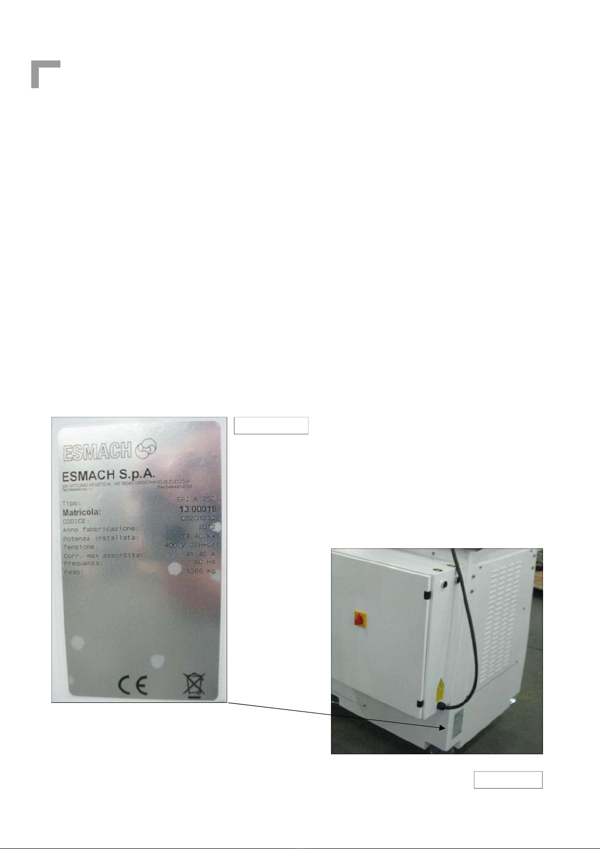
MACHINE IDENTIFICATION
Figure n° 1 shows the plate affixed to the machine in the position indicated by the arrow in fig-
ure n° 2. The plate contains all the information necessary for identifying the machine.
Figure n° 1
Figure n° 1
Figure n° 2

11
English
SECTION A - POINT 2
TECHNICAL SPECIFICATIONS
The main technical specifications of the machine are illustrated and indicated in figure n° 3 and in
tables on the following page.
Bowl rotation direction
(overhead view): anticlockwise
Figure n° 3
SPI A Hybri 160 200 250 300
A mm 1656 1656 1654 1654
B mm 832 8 2 857 37
C mm 00 00 1045 1045
D mm 1862 1833 1 54 1 13
E mm 1127 1127 1200 1200
F mm 1860 1860 1 83 1 83

12
Instruction for use an maintenance
Spiral mixer with removable bowl SPI 160-300 A HYBRID
(*) indicative value
TECHNICAL DATA 160 200 250 300
Maximum mixture capacity kg 160 200 250 300
Maximum flour capacity kg 100 125 150 185
Total capacity litres 250 300 360 430
Spiral arm speed 50 Hz (*) r.p.m. 86-172 86-172 86-172 86-172
Bowl speed 50 Hz (*) r.p.m. -18 -18 10-20 10-20
Power with 50 Hz kW 10,1 10,1 12, 12,
Packaging volume m
3
4,4 4,4 4,4 4,4
Net weight of machine kg 1210 1220 1370 1380
Bowl speed 60 Hz (*) r.p.m. 10.8-21.6 10.8-21.6 12-24 12-24
Spiral arm speed 60 Hz (*) r.p.m. 103-206 103-206 103-206 103-206
Power with 60 Hz kW 12, 12, 15,1 15,1
13
English
SECTION A - POINT 3
APPLICATION
The spiral mixer, also called “machine” in this manual, is designed exclusively for blending flour
for bread, cakes and other baked products with ingredients such as sugar, fat, salt, water, yeast
etc. in bakeries and food shops. A very wide variety of ingredients can be mixed. The complete
operation normally consists of a number of cycles of varying duration.
Use of the machine for purposes other than those specified above is dangerous for the operator
and for the machine itself. In the same way, machine installation and/or operation procedures
other than those specified in Section B points 2 and 3 can injure the operator and damage the
machine.
.
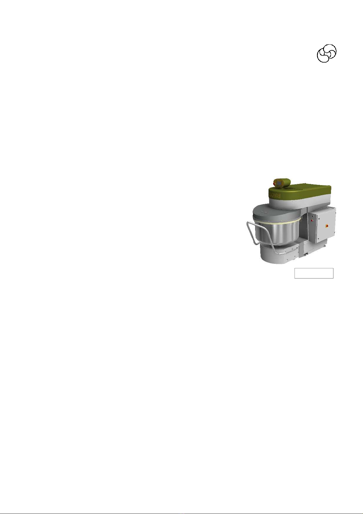
SEZIONE A - PUNTO 4
MACHINE DESCRIPTION
The machine consists basically of:
▪ one fixed structure with
- on the side the switchboard and the operating devices
- inside are the mechanical transmission parts:
-for the head upstroke
-for trolley coupling
-for bowl transmission
▪ a mobile head bound to the fixed structure equipped with:
- a tool for mixing the ingredients
- a central bar that guarantees a better dough oxygenation
- an electronic panel placed in the machine front part.
▪ a removable trolley
- a bowl for containing the ingredients to be mixed
- all the organs that allows the coupling to the central structure
Main features:
-the machine emits a weighted equivalent continuous acoustic pressure level ≤ of 70 dB (A).
-The machine as a whole is protected to IP 44.
Note:
Further details of the machine with illustrations are given in Section B point 3.
SECTION A - POINT 5
PREVENTIVE MEASURES AGAINST HEALTH AND SAFETY HAZARDS
In design and construction of the machine, the manufacturer has taken into account the results
of a previous assessment of SAFETY AND HEALTH hazards relating to use of the machine.
The protections and safety devices fitted on the machine are therefore the result of the com-
pany’s considerable efforts to achieve state-of-the-art safety levels as indicated in the specific
EEC directives.
Figure n° 4

14
Instruction for use an maintenance
Spiral mixer with removable bowl SPI 160-300 A HYBRID
The machine conforms to:
▪ the Directive 8/37 CEE
▪ the Directive CEM 8 /336 CEE
▪ the Directive BT 73/23 CEE
▪ the specific product standard EN 453 dated August 1 where the major apllicable stan-
dard are listed.
The machine complies with the laws in effet when it was delivered.
To adapt the equipment to any subsequent modification of standards is under the responsability
of the user. In this case, he has to ask the manufacturer whether a modification is necessary.
PREVENTIVE MEASURES AGAINST MECHANICAL HAZARDS
TOOL (SPIRAL ARM) OPERATING AREA
(Figure n° 5 zone 1)
The bowl is protected in the front part with a stainless steel closed protection and in the rear
part with a flour protection sheet.
The head and its protection opening is temporized as per EN 453 to let the toll stops in 4 sec-
onds from the opening of the machine head.
SPACE BETWEEN BOWL AND STRUCTURE (Figure n° 5
zone 2)
It conforms to the specific product standard EN 453.
MECHANISM OF BOWL MOVEMENT (Figure n° 5 zone 3)
Parts in movement advised by warning stickers in order
to maintain the safety.
POSITIONING AND ADJUSTING MECHANISMS
(Figure n° 5 zone 4)
All motions of the machine are essentially made by hold-to-run control devices (double
push buttons) and doesn’t present risks for the operator.
Note: the operator must be sure there is no person near the machine.
Remove the guards with the specific tools, to accede to the moving elements of the transmission
for inspection, cleaning and maintenance purpose.
BOWL GUIDE DEVICE (figure n° 5 zone 5)
The zone is protected by fixed guards as per EN 453.
In any case we suggest to not insert the fingers in that zone to avoid possible crushing
Figura n° 5
1
5
3
4
2
15
English
MACHINE STABILITY
The mixer is provided with adjustable feet with anti-slide rubber.
After having correctly positioned the feet (as explained in SECTION B POINT 2), the machine be-
comes automatically stable and does not require anchoring to the floor
PREVENTIVE MEASURES AGAINST ELECTRICAL HAZARDS
The preventive measures provided for by the EN 60204-1 standard have been adopted against
the danger of direct and indirect contact and all the tests provided for by the above standard
have been performed as certified in the attachment to the EC declaration of conformity. All the
tests provided for by the current technical regulations have also been carried out for implemen-
tation of the EEC directive on EMC.
PREVENTIVE MEASURES TO GUARANTEE HYGIENE
The following should be noted in particular:
A. The elements or parts of the machine (bowl, tool, dividing blade and bowl protection) that are
meant to come in contact with the dough ingredients or are in the so-called FOOD AREA are
made of STAINLESS STEEL (the bowl protection can be made of Transparent thermoformed
suitable for contact with food).
B. The elements or parts of the machine that may come into contact with the above food
products or are in the so-called DIRTYING OR SPLASH AREA are made of STAINLESS STEEL
or OVEN PAINTED STEEL.
C. The machine is in conformity with the principles of design to ensure the cleanability of the
machine as per EN 453.
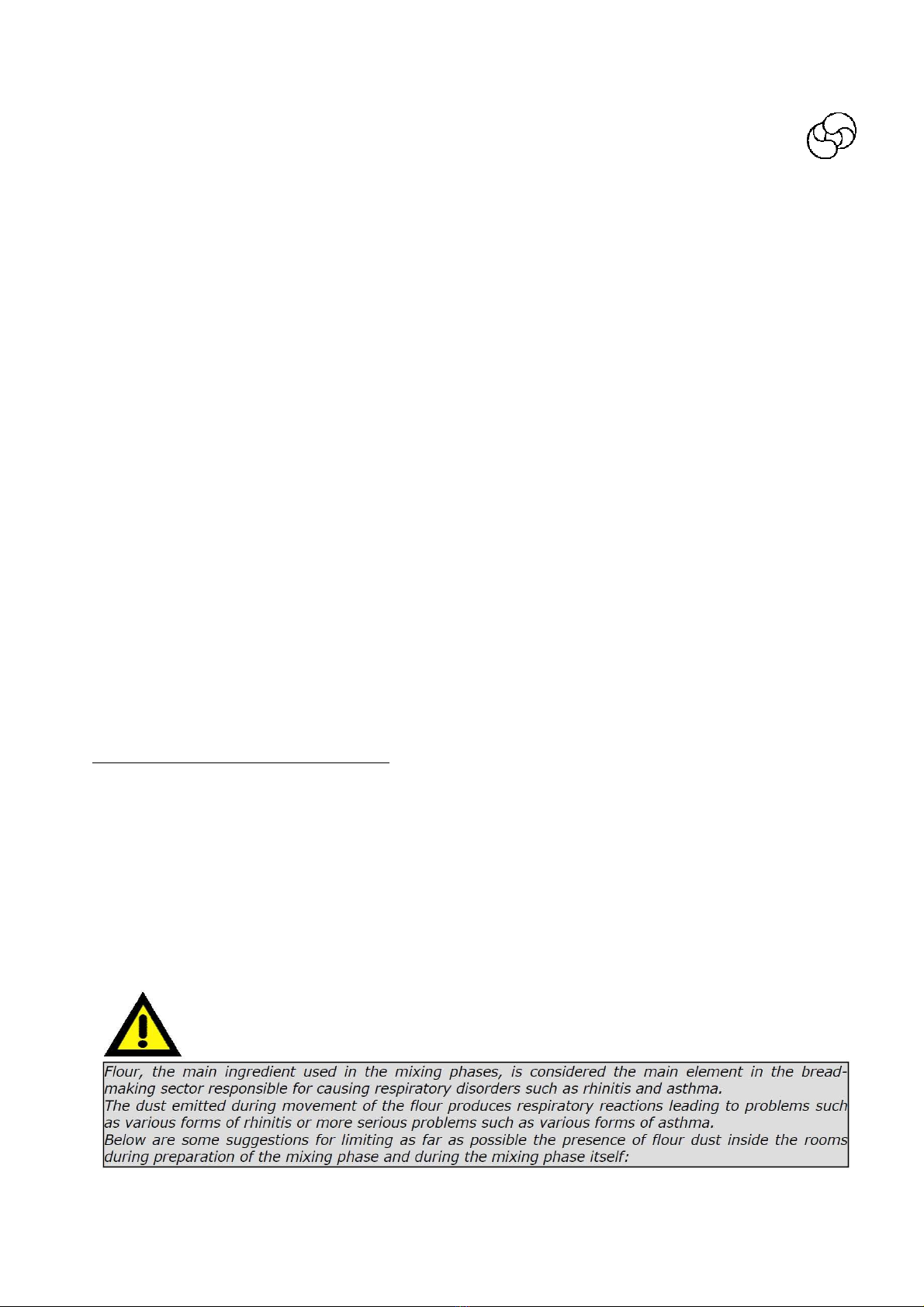
Measures to protect against flour dust
MEASURES FOR THE REDUCTION OF FLOUR DUST EMISSIONS.
The flour is a powdery agent that can impair the operator health (respiratory illnesses), and
therefore it must be handled in such way to limit to a minimum the presence of flour dust within
the premises.
As concern the machine, if it is equipped with s/s grille, its operating time in the first speed can-
not be set up to a value lower than 120 seconds (ref. EN 453) in order to limit the production of
flour dust.
Other warnings useful for operators who regularly handle flour are provided below.

16
Instruction for use an maintenance
Spiral mixer with removable bowl SPI 160-300 A HYBRID
PREVENTIVE MEASURES AGAINST NOISE HAZARDS
When the machine is operating empty, which is considered the most unfavourable condition, it
emits a weighted equivalent continuous acoustic pressure level of ≤ 70 dB (A).
It can be affirmed that the machine does not produce harmful noise or noise requiring the use
of headsets or earplugs.
SECTION A - POINT 6
SAFETY SIGNS - SYMBOLS
The safety signs are affixed to the machine by
means of stickers designed to draw the opera-
tor’s attention to possible hazards and to en-
sure his safety.
Make sure that the colours and wording of the
signs and symbols are always in perfect condi-
tion. At the first signs of deterioration, imme-
diately request replacements from your sup-
plier or the manufacturer.
B
F
H
D
C
E
G
A
Figure n° 6

17
English
SYMBOL DESCRIPTION
DO NOT REMOVE THE SAFETY DEVICES
CAUTION – DANGER OF CRUSHING
DANGER – LIVE PARTS
VOLTAGE
EARTH
BOWL AND TOOL ROTATION DIRECTION
PE OUTER PROTECTION WIRE TERMINAL
CAUTION – READ THE INSTRUCTION MANUAL
References
A
B
C
D
E
F
G
H

18
Instruction for use an maintenance
Spiral mixer with removable bowl SPI 160-300 A HYBRID
SYMBOLS ON CONTROL PANEL
“Advanced control panel”
Figure n° 7
SYMBOL DESCRIPTION SYMBOL DESCRIPTION
PROGRAMME QUICK RECALL KEY
FUNCTION KEY
PROGRAMME QUICK RECALL KEY
AUTOMATIC/MANUAL CYCLE KEY
BOWL INVERSION
CYCLE START KEY
PROGRAMME KEY
ENTER KEY
FUNCTION KEY
CYCLE STOP KEY
FUNCTION KEY
FUNCTION KEY
EMERGENCY BUTTON

1
English
SYMBOLS ON CONTROL PANEL
“Simplified control panel”
Figure n° 8
SYMBOL DESCRIPTION SYMBOL DESCRIPTION
START CYCLE KEY
AUTOMATIC/MANUAL CYCLE KEY
STOPO CYCLE KEY
PROGRAM SELECTION/PROGRAM
CONFIRMATION KEY
BOWL INVERSION KEY
EMERGENCY PUSH BUTTON
DECREASING KEY “DOWN”
INCREASING KEY “UP”
SECTION B - POINT 1
TRANSPORT, HANDLING AND STORAGE
The weight and overall dimensions of the machine are given in Section A point 2. The machine is
shipped assembled and packed in a case/crate/pallet made of nailed wooden boards provided
with the symbols and indications for handling. The operators in charge of handling the load must
be qualified and adequately trained. Store the machine in a dry ventilated room and cover it
with a protective sheet.
will stabilize the machine.
20
Instruction for use an maintenance
Spiral mixer with removable bowl SPI 160-300 A HYBRID
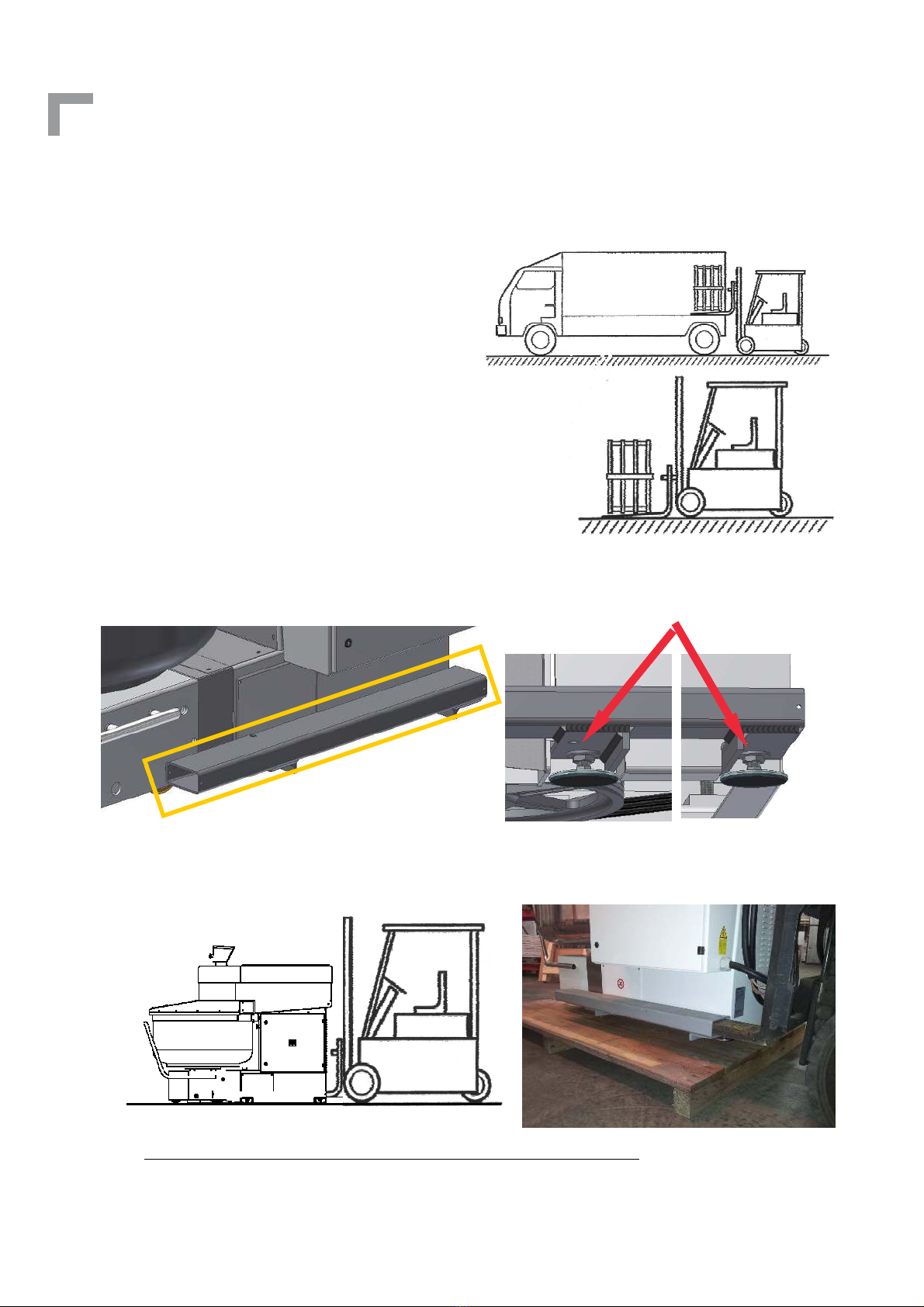
EXAMPLE OF MACHINE UNLOADING WITH FORKLIFT TRUCK
Stage 1: Unload the machine from the lorry in its
packaging;
Stage 2: Rest the machine on the ground;
Stage 3: Unpack the machine;
Stage 4: Make sure that the machine in its complex is in equi-
librium .
Stage 5: Make sure that the brackets for lifting are properly inserted on the feet of the machine
and fixed with nuts of the same feet.
Stage 6: Lift the machine avoiding sudden movements.
Stage 7: Only after standing the machine DOWN in the desired position, loosen the nuts on the
feet and remove the brackets from the side. The nuts will be fixed later when it will stabilize the
machine.
BRACKET FOR
LIFTING
FIXING NUTS
This manual suits for next models
3
Table of contents
Languages:
Other Esmach Mixer manuals

Popular Mixer manuals by other brands


TEFAL
TEFAL Prep Line HT4121 manual

Mondial Designs Limited
Mondial Designs Limited M-11 Instruction and Technical Service Manual

Mackie
Mackie 16-8 BUS HOOK-UP GUIDE

VOX electronics
VOX electronics MX-9105 operating instructions

cecotec
cecotec Cecomixer Easy instruction manual

stayer
stayer M1100B operating instructions