ESO VME4ST BACKPLANE User manual

VERY LARGE TELESCOPE
ESO VME4ST
BACKPLANE
TECHNICAL MANUAL
VLT-MAN-ESO-17130-0992
ISSUE 1
DATE 06-MAR-97
Prepared : J. Brynnel 06-MAR-97 .
Name Date Signature
Approved : W. Nees 06-MAR-97 .
Name Date Signature
Released : M. Ziebell 06-MAR-97 .
Name Date Signature

Page 2
06-Mar-1997
VME4ST Backplane technical manual Doc. VLT-MAN-ESO-17130-0992
Change record
Issue Date Part affected Remark
1 6-Mar-97 All First issue

Page 3
06-Mar-1997
VME4ST Backplane technical manual Doc. VLT-MAN-ESO-17130-0992
Table of contents
Change record..........................................................................................................................................2
Table of contents......................................................................................................................................3
1. INTRODUCTION................................................................................................................................4
1.1. Scope...................................................................................................................................4
1.2 Reference documents............................................................................................................4
2. OVERVIEW.........................................................................................................................................4
2.1 System ..................................................................................................................................4
3. BACKPLANE LAYOUT .....................................................................................................................7
4. CONNECTIONS..................................................................................................................................8
4.1 MAC4 connector ..................................................................................................................8
4.1.1 /STEP1 - /STEP4 ...............................................................................................9
4.1.2 /DIR1 - /DIR4.....................................................................................................10
4.1.3 /EN1 - /EN4........................................................................................................11
4.1.4 HPWR1 - HPWR4 .............................................................................................12
4.1.5 A,B,Z (Encoder Signals) ...................................................................................13
4.1.6 /DF1 - /DF4 (Drive Fault) ..................................................................................15
4.1.7 FC0-FC2.............................................................................................................16
4.1.8 /STOP.................................................................................................................18
4.1.9 /HOME1 to /HOME4.........................................................................................19
4.1.10 /SP1 to /SP4 and /SN1 to /SN4 ......................................................................20
4.1.11 GND.................................................................................................................21
4.2 VME4ST connector..............................................................................................................22
4.2.1 PH1+ to PH5+, PH1- to PH5-............................................................................23
4.2.2 +VMH, +VML, GNDB......................................................................................24
4.2.3 +5VA, GNDA ....................................................................................................25
4.2.4 /DF1 - /DF4........................................................................................................26
4.2.5 UL+, UL-, LL+ and LL-.....................................................................................26
4.2.6 /EN.....................................................................................................................26
4.2.7 HPWR................................................................................................................26
4.2.8 /STEP .................................................................................................................26
4.2.9 /DIR....................................................................................................................26
4.2.10 LCK+ and LCK -..............................................................................................27
4.2.10.1 Operation without using LOCK inputs............................................28
4.2.10.2 LOCK operation using external contact..........................................28
4.2.10.3 LOCK operation using external current source...............................29
4.2.11 STOP+ and STOP-...........................................................................................29
4.3 Motor connectors CH1 - CH4..............................................................................................30
4.3.1 Motor..................................................................................................................32
4.3.2 Encoder ..............................................................................................................32
4.3.3 Limit switches (UL and LL)...............................................................................32
4.3.4 Reference position switch (HOME) ..................................................................32
4.3.5 VX......................................................................................................................33
4.3.6 +5VA..................................................................................................................34
4.3.7 SPA,SPB ............................................................................................................34
4.4 Motor power supply connection ..........................................................................................35
5. MECHANICAL INSTALLATION.......................................................................................................36

Page 4
06-Mar-1997
VME4ST Backplane technical manual Doc. VLT-MAN-ESO-17130-0992
1. INTRODUCTION.
1.1. Scope.
This document describes the ESO VME4ST backplane. This is a special VME-bus P2
backplane which is used for interconnecting a MAC4-STP stepper motor motion controller
with a VME4ST stepper motor driver (power amplifier).
Field signals necessary for operating the four stepper motor axes, as well as motor power
supply and interlock signals, connect to the rear side of this backplane.
Backplane mechanical installation is described in Sect 5.
All signals connected to/from MAC4-STP motion controller are described in Sect. 4.1.
Signals connected to/from VME4ST amplifier are described in Sect. 4.2.
External signals connection is described in Sect. 4.3 - 4.4
Users only interested in connecting a motor, limit switches etc. should proceed directly to
Sections 4.3 and 4.4.
The document shall also be used as a reference for ESO standardised field wiring for stepper
motor applications in instrument control systems.
1.2 Reference documents.
(RD1) : VLT-MAN-ESO-17130-0991 "ESO VME4ST 4-channel Stepper Motor Driver"
(RD2) : Technical description - “Benutzerhandbuch MAC4-STP”, Maccon GmbH.
2. OVERVIEW
2.1 System
The VME4ST backplane is a part of a (ESO defined and standardised) VME-based Stepper
Motor motion control system consisting of :
* MAC4-STP 4-axes Stepper motor motion controller board,
* ESO VME4ST 4-axes Stepper motor driver board and
* ESO VME4ST Backplane.
These three units form a compact, high performance versatile stepper motor motion control
system. Its prime use is for VLT instrument control system.
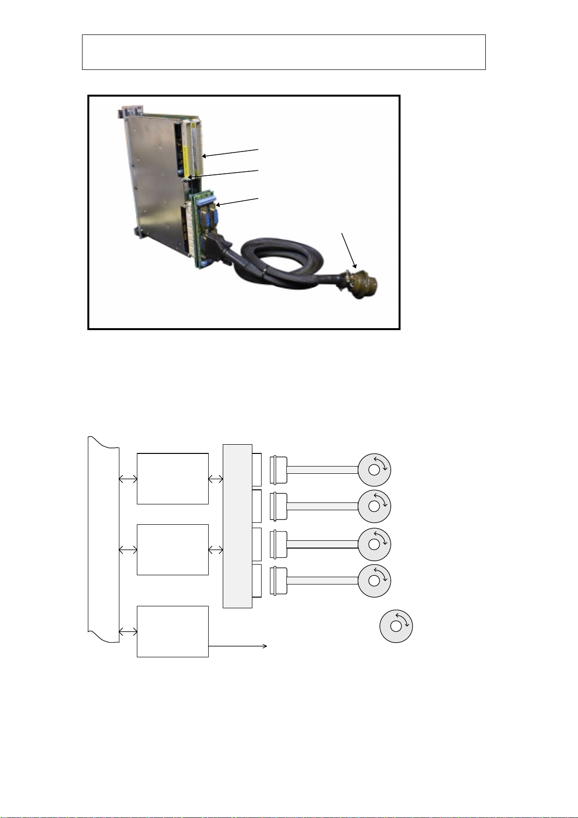
As illustrated in fig. 2.1.1, the backplane interconnects the MAC4 motion controller and the
VME4ST power amplifier at VME P2 level. The four controlled functions (mechanical
functions with a motor, encoder as well as status switches) are connected to the back side of
the VME4ST backplane through four (4) identical connectors (one connector for each
function).
Each one of these connectors provides access to all signals related to one function, including
motor, limit, reference and (optionally) encoder signals, thus simplifying field cabling
significantly. See also fig. 2.1.3., where the basic signals of one function are illustrated.
Page 5
06-Mar-1997
VME4ST Backplane technical manual Doc. VLT-MAN-ESO-17130-0992
MAC4/STP Motion Controller
VME4ST Motor Driver
VME4ST Backplane Assembly
To motor function
Fig 2.1.1. MAC4-STP , VME4ST motor driver, and VME4ST backplane.
{
VME
BUS
MAC4
MOTION
CONTROLLER
VME4ST
STEPPER
MOTOR AMP.
VME4ST
P2 BACKPLANE
4-AXES
4-AXES
CH1
CH2
CH3
CH4
LCU CPU
F I
F II
F III
F IV
TO LAN
(ETHERNET)
MOTOR
REFERENCE
(ENCODER)
=
LIMIT SWITCHES
Fig 2.1.2. System block schematics.
Each function has access to signal ground, +5V supply, a user provided voltage supply and
two unallocated signals SPA and SPB (user disposable). Note that in fig. 2.1.3. all signals are
indicated as logical rather than physical connections. For a more detailed description of the
connections, see section 4.

Page 6
06-Mar-1997
VME4ST Backplane technical manual Doc. VLT-MAN-ESO-17130-0992
VME
BUS
MAC4/STP
VME4SA -X1
VME4ST
P2 BACKPLANE FIELD (FUNCTION)
CONNECTOR
(ONE OF FOUR SHOWN)
LIMITS
STEP/BOOST/EN
FAULT
LIMITS
STEP/BOOST/EN
FAULT
REF.POSITION
ENCODER
+5V
MOTOR
STOP/LOCK
P1 P2
P1 P2
+5V
MOTOR P.S.
REF.POS. (HOME)
ENCODER
LIMIT SWITCHES
SPA + SPB
GND
+5V
MOTOR
VX
VX
MOTOR
POWER
J1
CODE CODE
POSITION
J2
Fig 2.1.3. Signal overview. Figure shows logical connections.

Page 7
06-Mar-1997
VME4ST Backplane technical manual Doc. VLT-MAN-ESO-17130-0992
3. BACKPLANE LAYOUT
Spare signalsVx
Motor CH1
Motor CH3
Motor CH2
Motor CH4
Motor power
input
Motor stop
and interlock
MAC4/STP VME4ST
Backplane
address
select
SW1
Fig 3.1 Field (rear) side Fig 3.2. VME-slot side.
Figure 3.1. shows the backplane seen from the VME-chassis rear, or function (field)
connector side. From this side the user has access to the four function connectors CH1-CH4,
screw terminals for connection of User Power Supply Vx, spare signals, motor interlock and
stop signals, and power terminals for connection of motor power supply.
In figure 3.2. (seen from VME-chassis front side) the P2 connectors for MAC4-STP and
VME4ST power amplifier are shown. From this side one can also access the backplane
address setting switches.

Page 8
06-Mar-1997
VME4ST Backplane technical manual Doc. VLT-MAN-ESO-17130-0992
4. CONNECTIONS
In Sect. 4.1 all MAC4-STP motion controller signals, and in Sect. 4.2 all VME4ST amplifier
signals are described.
External signals are described in Sect. 4.3 - 4.4.
4.1 MAC4 connector
Pin # C B A
1/DIR3
2 /DIR1 GND
3 /STEP1 GND
4 /STEP2 /STEP3
5A1+ /STEP4
6 A1- B1+
7 Z1+ B1-
8 Z1- A2+
9 B2+ A2-
10 B2- Z2+
11 A3+ Z2-
12 A3- B3+
13 Z3+ B3-
14 Z3- A4+
15 B4+ A4-
16 B4- Z4+
17 HPWR1 Z4-
18 HPWR2 HPWR3
19 /EN1 HPWR4
20 /EN2 /EN3
21 /DF1 /EN4
22 /DF2 /DF3
23 FC0 /DF4
24 FC1 FC2
25 /DIR2 /DIR4
26 GND /STOP
27 /SN1 /SP1
28 /HOME1 /SP2
29 /HOME2 /SN2
30 /SP3 /SN3
31 /SP4 /HOME3
32 /SN4 /HOME4
Fig 4.1. Pin allocation of MAC4-STP connector on VME4ST backplane (VME chassis rear
view).

Page 9
06-Mar-1997
VME4ST Backplane technical manual Doc. VLT-MAN-ESO-17130-0992
The MAC4 motion controller is connected (see also RD2) to the VME4ST backplane from
the VME-slot side to a (VME P2 connector) DIN 96-pole female connector, see fig 4.1. Only
rows A and C are used.
4.1.1 /STEP1 - /STEP4
Motor step command signal. Open collector type output from MAC4 to power amplifier.
Signals are routed from MAC4 connector to VME4ST power amplifier connector.
If the VME4ST amplifier is enabled, the motor moves one step on each negative edge of this
signal.
Note : In MACCON documentation (RD2), this signal is referenced to as P_OUT1 -
P_OUT4.
MAC4
VME4ST
VME4ST P2 BACKPLANE
MOTOR
CONNECTOR
(ONE AXIS)
P_OUT
/STEP
VME
BUS
/STEP
Fig 4.1.1. /STEP signal connection.

Page 10
06-Mar-1997
VME4ST Backplane technical manual Doc. VLT-MAN-ESO-17130-0992
4.1.2 /DIR1 - /DIR4
Motor direction command signal. Open collector type output from MAC4 to power amplifier.
Signals are routed from MAC4 connector to VME4ST power amplifier connector.
A step pulse from MAC4-STP will result in a motor move in the following direction :
/DIR output : Motor moves :
/DIR output off (High) Negative direction (CCW)
/DIR output on (Low) Positive direction (CW)
MAC4
VME4ST
VME4ST P2 BACKPLANE
MOTOR
CONNECTOR
(ONE AXIS)
/DIR
VME
BUS
Fig 4.1.2. /DIR signal connection.

Page 11
06-Mar-1997
VME4ST Backplane technical manual Doc. VLT-MAN-ESO-17130-0992
4.1.3 /EN1 - /EN4
Motor enable command signal. Open collector type output from MAC4 to power amplifier.
Signals are routed from MAC4 connector to VME4ST power amplifier connector.
With this signal MAC4-STP controls the output stages of VME4ST amplifier as follows :
/EN output Amplifier status
/EN output off (High) Output stage off (no motor current)
/EN output on (Low) Output stage on
The status of this signal can be monitored on the front panel of MAC4, where a LED ‘D’
(Disable) for each channel will light when the corresponding /EN signal is off.
MAC4
VME4ST
VME4ST P2 BACKPLANE
MOTOR
CONNECTOR
(ONE AXIS)
/EN
VME
BUS
/EN
Fig 4.1.3. /EN signal connection.
Page 12
06-Mar-1997
VME4ST Backplane technical manual Doc. VLT-MAN-ESO-17130-0992
4.1.4 HPWR1 - HPWR4
Motor power level command signal. Open collector type output from MAC4 to power
amplifier. Signals are routed from MAC4 connector to VME4ST power amplifier connector.
With this signal MAC4-STP controls the motor output power of VME4ST amplifier as
follows :
HPWR output Motor current
HPWR output high (off) Full current
HPWR output low (on) Low current
The status of this signal can be monitored on the front panel of VME4ST amplifier, where
two LED’s (HP and LP) for each channel indicate motor power level :
LED “LP”
(Low Power) LED “HP”
(High Power) Motor power
Off Off Off (Motor disable)
On Off Low power (Position hold)
Off On High power (Motor run)
On On -
Note 1 : The motor power (High / Low) is also affected by jumper settings on VME4ST
amplifier, consult (RD1) for details.
Note 2 : In MACCON documentation, this signal is referenced to as BOOST1 - BOOST4.
MAC4
VME4ST
VME4ST P2 BACKPLANE
MOTOR
CONNECTOR
(ONE AXIS)
HPWR
VME
BUS
HPWR
BOOST
Fig 4.1.4. HPWR signal connection.

Page 13
06-Mar-1997
VME4ST Backplane technical manual Doc. VLT-MAN-ESO-17130-0992
4.1.5 A,B,Z (Encoder Signals)
Incremental encoder signals. Input to MAC4-STP. TTL-level differential signals. Signals are
routed from function connectors CH1-CH4 to MAC4. Signal names are abbreviated as
follows :
Signal name Signal
A1+ Axis 1, Encoder signal A, Positive
A1- Axis 1, Encoder signal A, Negative
B1+ Axis 1, Encoder signal B, Positive
B1- Axis 1, Encoder signal B, Negative
Z1+ Axis 1, Encoder signal Z, Positive
Z1- Axis 1, Encoder signal Z, Negative
MAC4
VME4ST
VME4ST P2 BACKPLANE
MOTOR
CONNECTOR
(ONE AXIS)
VME
BUS
A+
A-
B+
B-
Z+
Z-
A+
A-
B+
B-
Z+
Z-
GNDG
N
D
SIGNAL A
SIGNAL B
SIGNAL Z
Fig 4.1.5.1. Incremental encoder signal connection. Only one axis shown.
Important note :
For stepper motor applications, normally no encoder is used. In these cases note that it is
extremely important to terminate the encoder inputs externally, in particular the Z+ and Z-
inputs. If this is not done, there is a high probability that MAC4-STP firmware will get stuck
due to internal hardware structure (noise pickup on high impedance inputs). If no encoder
will be used, either of the two following actions MUST be taken :
Page 14
06-Mar-1997
VME4ST Backplane technical manual Doc. VLT-MAN-ESO-17130-0992
Solution A (External) : Connect (for all four axes) encoder input Z- to Ground and/or input
Z+ to +5V.
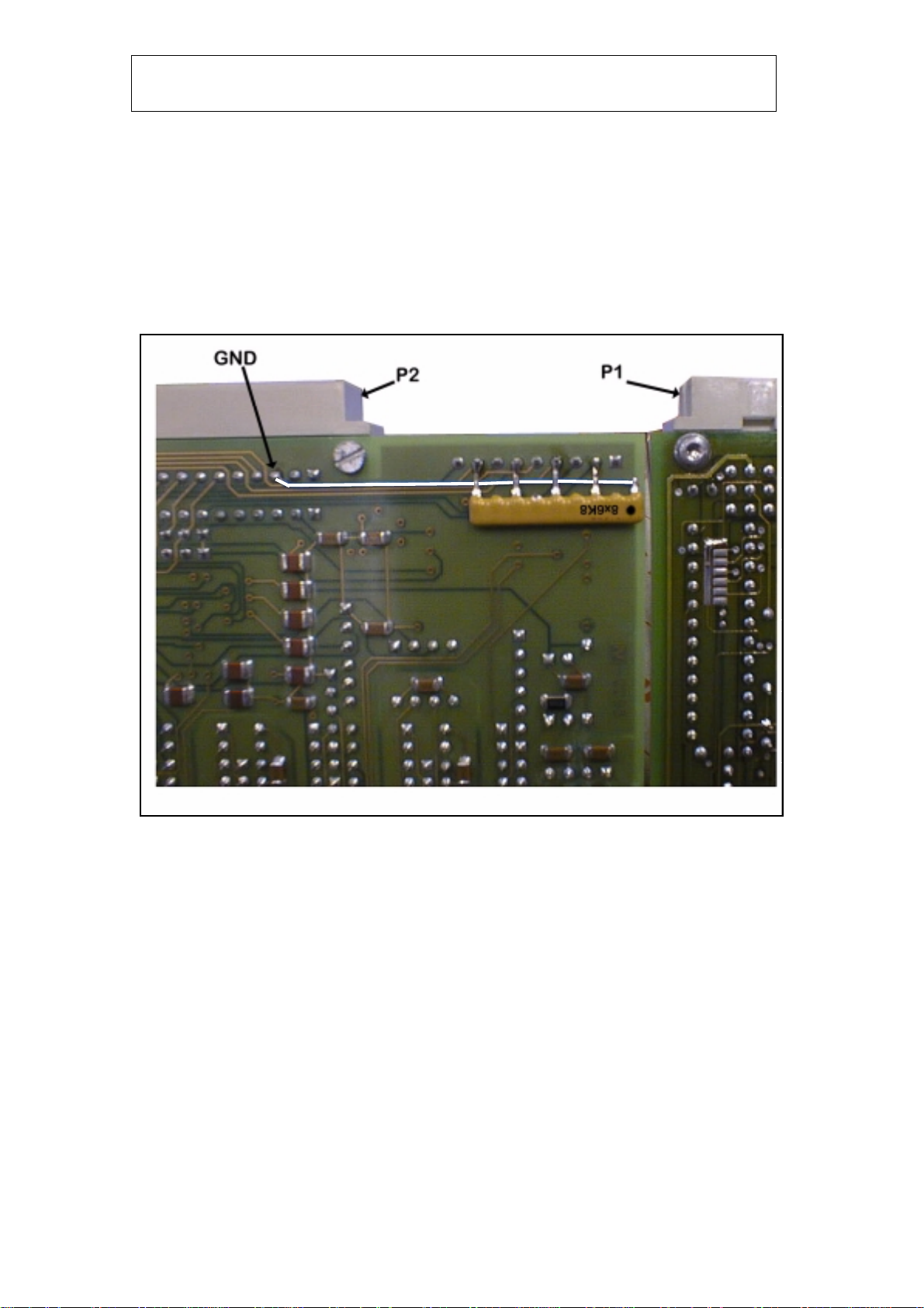
Solution B (MAC4-STP on-board) : Add one resistor network 8 x 6k8 (9-pin) to the solder
side of MAC4STP. See Fig. 4.1.5.2 below.
Fig 4.1.5.2. MAC4-STP on-board modification (alternative 2).
If the modification shown in Fig. 4.1.5.2. is done, please note the following :
1. This modification is for all four axes.
2. It is possible to connect an encoder also after this modification.

Page 15
06-Mar-1997
VME4ST Backplane technical manual Doc. VLT-MAN-ESO-17130-0992
4.1.6 /DF1 - /DF4 (Drive Fault)
Drive fault channel I to IV. Input to MAC4 from VME4ST amplifier. A high level on this
signal to MAC4 indicates that the power amplifier is OK.
Note 1 : Important ! Close the jumpers BR8, BR12, BR16, BR20 on MAC4-STP to adapt
the four /DF inputs, respectively, for TTL-level inputs. If the jumpers are not closed, the
inputs are configured for +24V level inputs, and will not work.
Note 2 : When the VME4ST amplifier is not inserted into its VME slot, the drive fault inputs
of the MAC4 unit are low, thus indicating drive fault.
MAC4
VME4ST
VME4ST P2 BACKPLANE
MOTOR
CONNECTOR
(ONE AXIS)
/DF
VME
BUS
/DF
OPTO-
COUPLER
EPLD
Fig 4.1.6. Drive fault (-DF) signal connection.

Page 16
06-Mar-1997
VME4ST Backplane technical manual Doc. VLT-MAN-ESO-17130-0992
4.1.7 FC0-FC2
VME4ST Backplane Assembly Address setting bit 0-2. Input to MAC4 motion controller
from position code switch array SW1 on backplane. See also Fig. 3.2.
The purpose of the address coding is to provide to the VME master CPU a VME-slot
identification mechanism if several sub-sets of motion control systems exist within the same
VME LCU.
Each VME4ST backplane within one VME-bus chassis must be given a unique address as
listed in table 4.1.7 :
MAC4 # MAC4 base address Backplane address SW1 position1
1 0xC10000 1 ON-OFF-OFF-X
2 0xC20000 2 OFF-ON-OFF-X
3 0xC30000 3 ON-ON-OFF-X
:: ::
7 0xC70000 7 ON-ON-ON-X
Table 4.1.7. VME4ST backplane addresses.
MAC4
VME4ST
VME4ST P2 BACKPLANE
MOTOR
CONNECTOR
(ONE AXIS)
VME
BUS
FC2
OPTO-
COUPLERS
FC1
FC0
G
N
D
SW1
1234
V
C
CFUSE 1.5A
Fig 4.1.7.1. Backplane address signal connection.
Note : When the VME4ST servo amplifier is not present, the address code inputs FC0-FC2
of the MAC4 unit will all be low (0) because the pull-up resistors are supplied with
+5V from the VME4ST board.
1Indication of individual switch 1,2,3,4 position. See fig 4.1.7.2. OFF = switch open (left position),
ON = switch closed (right position), X = don’t care.

Page 17
06-Mar-1997
VME4ST Backplane technical manual Doc. VLT-MAN-ESO-17130-0992
MAC4 P2 VME4ST P2SW1
4
3
2
1
ONOFF
Fig 4.1.7.2. Backplane address switch SW1 location.

Page 18
06-Mar-1997
VME4ST Backplane technical manual Doc. VLT-MAN-ESO-17130-0992
4.1.8 /STOP
This is an emergency stop signal input to the MAC4 board. This signal is not externally
available to the user. If emergency stop or motor interlock is required, use the backplane
STOP/IL input signals, see Sect. 4.2.10 and 4.2.11, which are connected to VME4ST
amplifier.
For MAC4-STP operation, however, it is required to supply this input with 12-24 VDC. If
this input is left unconnected, MAC4-STP will not operate. For this purpose, a DC/DC
converter generating +15 VDC is located on the VME4ST backplane, see Fig. 4.1.8 below.
Note : When VME4ST servo amplifier is not inserted into the VME-system, the -STOP
input of the MAC4 unit will be low (0V) because the DC/DC converter is supplied
with +5V from the VME4ST board.
MAC4-STP
VME4ST
VME4ST P2 BACKPLANE
MOTOR
CONNECTOR
(ONE AXIS)
VME
BUS
OPTO-
COUPLER
/STOP
G
N
D
DC/DC
5V/15V
V
C
CFUSE 1.5A
INOUT 5V15V
Fig 4.1.8. Emergency stop (-STOP) signal connection.

Page 19
06-Mar-1997
VME4ST Backplane technical manual Doc. VLT-MAN-ESO-17130-0992
4.1.9 /HOME1 to /HOME4
Reference position (home) signal 1-4. This signal is used for initialising motor position in
some applications. For detailed description of how to use these signals, see MAC4 manual.
Signals are routed from function connectors CH1-CH4 to MAC4 motion controller via opto-
couplers on the backplane. If the /HOME pin is left unconnected in the function connector
(CH1-CH4) the MAC4 reads ON reference position. A grounded input will be interpreted as
OFF reference position.
MAC4-STP
VME4ST
VME4ST P2 BACKPLANE
MOTOR
CONNECTOR
(ONE AXIS)
VME
BUS
OPTO-
COUPLER
/RS
G
N
D
OPTO-
COUPLER
V
C
CFUSE 1.5A
HOME
+5V
+5V
USER
REFERENCE
SWITCH
(EXTERNAL)
+5V
GNDA
Fig 4.1.9. Reference switch (/HOME) signal connection.
Note 1 : Important ! Close the jumpers BR7, BR11, BR15, BR19 on MAC4-STP to adapt
the four /DF inputs, respectively, for TTL-level inputs. If the jumpers are not closed, the
inputs are configured for +24V level inputs, and will not work.
Note 2 : When VME4ST servo amplifier is not seated in its slot, the reference position inputs
/HOME1 to /HOME4 of the MAC4 unit will all be low (ON reference position)
because the optocouplers are supplied from the VME4ST board.
Note 3 : In MACCON documentation, this signal is referenced to as -RS1 to -RS4.

Page 20
06-Mar-1997
VME4ST Backplane technical manual Doc. VLT-MAN-ESO-17130-0992
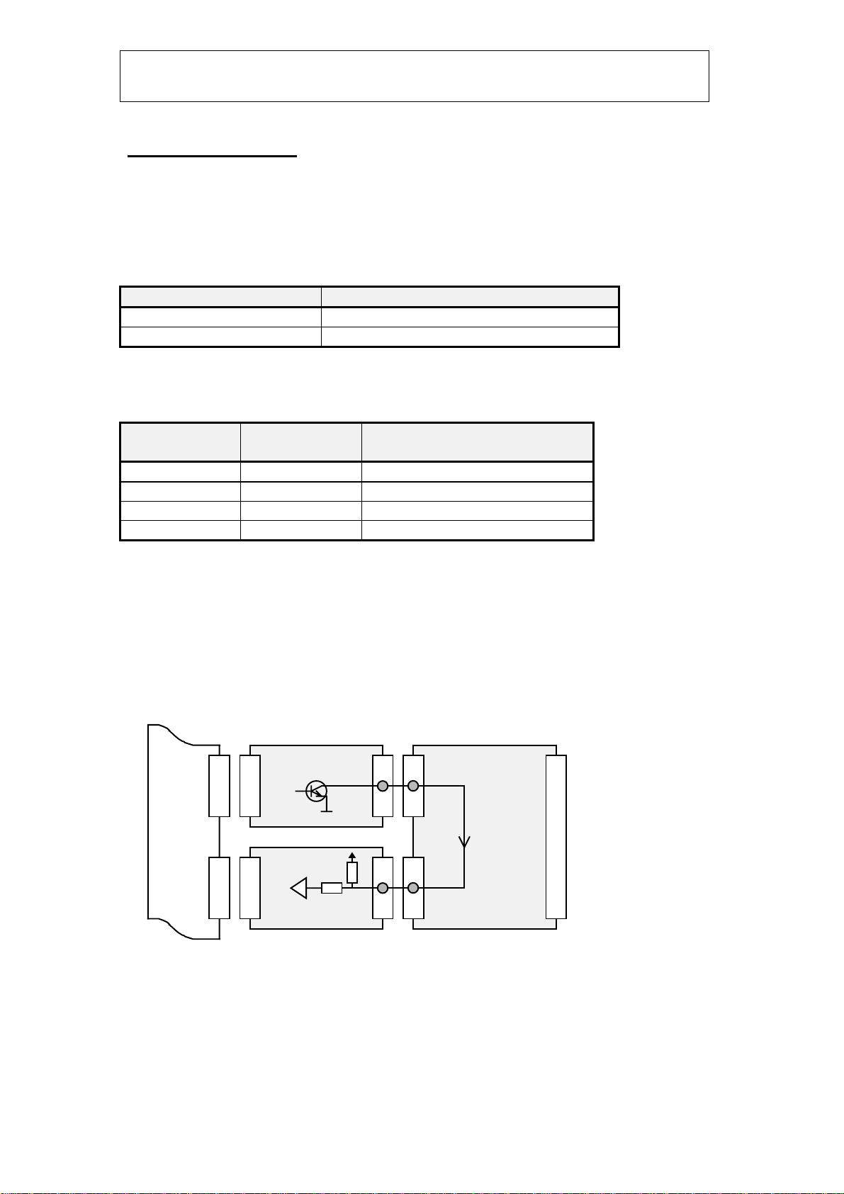
4.1.10 /SP1 to /SP4 and /SN1 to /SN4
Positive and Negative Limit switch input to MAC4 controller and VME4ST motor driver.
Signals are routed from Backplane motor connectors CH1-CH4 to MAC4 and VME4ST via
optocouplers. No current through the opto-couplers means ON limit, a current of 2-30 mA
means OFF limit. External circuitry for limit switches will consist of a normally closed
switch or transistor, which opens on limit condition.
If no limits are required (for instance a filter wheel with no mechanical end stops) the user
must connect a bridge (wire) between both limit inputs and ground. If an input is left open, it
will cause a limit condition, and the motor will not be able to move.
In Fig 4.1.10 below, the limit switch input circuitry is shown. Upper and lower limit switch
inputs are identical. In the figure only one input is shown.
If a limit switch input is activated, VME4ST amplifier will shut off motor current
immediately for motor rotation in one direction. Further, MAC4-STP will stop any movement
in this direction, and higher level software can read out limit switch status from the MAC4-
STP.
MAC4/STP
VME4ST
VME4ST P2 BACKPLANE
MOTOR
CONNECTOR
(ONE AXIS)
VME
BUS
OPTO-
COUPLER
/SP/SN
G
N
D
V
C
CFUSE 1.5A
ULIM/
LLIM
+5V
+5V
USER
LIMIT
SWITCH
(EXTERNAL)
+5V
GNDA
LL+/UL+
LL-/UL-
OPTO-
COUPLER
Fig 4.1.10. Limit switch inputs.
For further information about the connection of external devices like limit switches etc., see
figure 4.3.B (sample set-up) and section 4.3.3 (limit switch connection).
Note 1 : Important ! Close the jumpers BR5-6, BR9-10, BR13-14, BR17-18 on MAC4-STP
(RD2) to adapt the limit inputs, respectively, for TTL-level inputs. If the jumpers
are not closed, the inputs are configured for +24V level inputs, and will not work.
Table of contents
Other ESO Telescope manuals


Popular Telescope manuals by other brands


Meade
Meade 50 AZ-T instruction manual

Bushnell
Bushnell Deep Space 78-9003 user guide

ORION TELESCOPES & BINOCULARS
ORION TELESCOPES & BINOCULARS BX90 instruction manual

Orion
Orion StarBlast 6 instruction manual

Celestron
Celestron Celestar 8 instruction manual

Bresser
Bresser Venus 45-41000 Instructions for use


