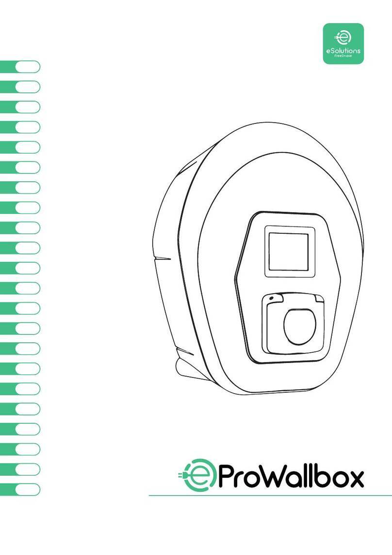
eSolutions PULSAR PLUS User manual

Installation Guide
eSolutions PULSAR PLUS


Manage Your Charger
with the eSolutions App
Let’s get started!
Commençons!
¡Empecemos!
Complete the installation of your Pulsar Plus.
Complétez l’installation de votre Pulsar Plus.
Completa la instalación de tu Pulsar Plus.
EN Download to:
FR Téléchargez pour:
• Connect your charger via Bluetooth.
• Add your charger to a Wi-Fi network.
• Manage and control your charger
with the app.
• Vous connecter à votre chargeur via Bluetooth.
• Ajouter votre chargeur à un réseau Wi-Fi.
• Gérer et contrôler votre chargeur à l’aide
de l’application.
Your charging unit is active and will work upon installation.
It does not require an app to use.
ES Descarga para:
• Conectarte a tu cargador vía Bluetooth.
• Conectar el cargador a tu red Wi-Fi.
• Controlar y gestionar tu cargador
usando la app.
Votre unité de charge est active et fonctionnera dès l’installation.
Il n’est pas nécessaire d’utiliser une application pour l’utiliser.
IMPORTANT:
Su unidad de carga está activa y funcionará una vez instalada.
No se requiere una aplicación para su uso.
IMPORTANT:
IMPORTANTE:

EN
ENGLISH
FRANÇAIS
INDEX
4
40
22
GETTING STARTED
5
9
6
10
9
10
9
10
9
10
Data Sheet
Package contents
Safety instructions
Before installing Pulsar Plus
Prepare the charger for installation
Components
Location
Required tools
Included mounting parts
Positioning
INSTALLATION
Hardwire installation
Holster
NEMA plug-in installation
11
12
13
14
15
19
16
20
17
20
18
16
19
17
20
12
14
11
11
14
14
15
19
NEMA outlet installation
Installing the wallplate
Placement
Mounting
Placement
Guide to LEDs
Installing the wallplate
Charging
Electrical wiring
Closing the charger
Installing the holster
Mounting the charger
Troubleshooting
Rated current adjustment
Preparing your charger
Registering and connecting
your charger
Existing NEMA outlet
Determine wiring entry
Powering on
Removing the NEMA 14-50P cable
Compatibility
Operating
ESPAÑOL

EN
5
General specifications
Model Pulsar Plus
Cable length
Color
25ft
Matte black
Dimensions 7.8” x 7.9” x 3.9” (without cable)
Charging protocol SAE J1772
Weight 4.4lbs (without cable)
Operating temperature
Storage temperature
EMC compliance
Electrical safety
-22ºF to 104ºF (-30ºC to 40ºC)
-40ºF to 158ºF (-40°C to 70°C)
FCC Part 15 Class B, CAN ICES-003B / NMB-003B
Contains FCC IDs: QOQBGM13P, 2ADHKWWILC3000
Contains ICs: 5123A-BGM13P, 20266-ATWILC3000
UL 2594, UL 2231, NMX-J-668/2-ANCE-2013
Part number structure
Electrical specifications
Charging Power
Rated Current
Rated voltage AC ± 10%
Connector type
Configurable current
Rated frequency
Enclosure protection rating
Power input connection
9.6kW 11.5kW
40A 48A
208/240 V (Level 2)
From 6A to rated current
SAE J1772 Type 1
60Hz
Type 4 per UL 50E
Plug connected (NEMA 14-50P) or hardwired
A
B
C
D
E
F
G
Code Definition
Model PUP1 Pulsar Plus NA
Cable U25ft
EVC 1Type 1
Power 5
611.5kW
9.6kW
Version
Custom
C
0
G
N
002
X
Hardwired + OCPP
Hardwired
NEMA 14-50P + OCPP
Plug-in version
Black
Revision X
Revision
PN: PUP1-U-1-5-C-002-A
A B FGD
CE
GETTING STARTED
Data Sheet
PN:XXXX-X-X-X-X-XXX-X
----
E506750 EVSE
Wallbox Chargers S.L.U.

6
EN
WARNING: Improper connection of the equipment-grounding conductor may
result in a risk of electric shock. Check with a qualified electrician or service
person if you are in doubt as to whether the product is properly grounded. Do not
modify the plug provided with the product. If it does not fit the receptacle, have a
proper receptacle installed by a qualified electrician.
• Read all instructions before installing and using your Free2move Charge Wallbox
charger.
• Permanent (hardwired) connection of your charger and/or installation of
electrical circuits, conduit, and NEMA receptacles must only be performed by a
qualified electrician in accordance with all local electrical codes and ordinances.
Unauthorized installation or modifications will void the manufacturer’s warranty.
• This device should be supervised when using around children.
• Do not put fingers into the electric vehicle connector.
• Do not use your Free2move Charge Wallbox charger if the flexible power cord or
EV cable is frayed, has broken insulation, or any other signs of damage.
• Do not use your Free2move Charge Wallbox charger if the enclosure or the EV
connector is broken, cracked, open, or shows any other indication of damage.
• Do not operate your Free2move Charge Wallbox charger in temperatures outside
its operating range of -22ºF to 104ºF (-30ºC to 40ºC).
• Do not open your charger in rain or other inclement weather.
• Do not open the front cover of your charger while it is connected to the power
supply.
• Install your charger in a suiciently ventilated location and avoid installation
in areas with direct sunlight.
• Do not install your Free2move Charge Wallbox charger near flammable,
explosive, or combustible materials.
• In case of flooding, do not operate your charger while it or your vehicle is
submerged in water.
• If your charger was submerged in water due to flooding, have a qualified
electrician inspect your charger prior to energizing or using your charger again.
Your Free2move Charge Wallbox charger must be grounded. If it should malfunction
or break down, grounding provides a path of least resistance for electric current
to reduce the risk of electric shock. Your charger is equipped with a cord having an
equipment grounding conductor and a grounding plug. The plug must be plugged into
an appropriate receptacle that is properly installed and grounded in accordance with all
local codes and ordinances.
Warning for AC plug-in products: Grounding instructions
WARNING: When using electric products, basic precautions should always be
followed, including those below. This manual contains important instructions that
cover the safe installation, operation and maintenance of the unit.
SAVE THESE INSTRUCTIONS |INSTRUCTIONS PERTAINING TO RISK OF FIRE OR ELECTRIC SHOCK.
GETTING STARTED
Safety instructions

7
EN
• Your Free2move Charge Wallbox charger contains no user serviceable parts.
Do not attempt to repair or service any other part of the unit yourself. If the
unit requires servicing, please contact customer service.
• The installation, maintenance, and servicing of your Free2move Charge
Wallbox charger must only be performed by qualified personnel in accordance
with applicable local regulations.
• Protect your Free2move Charge Wallbox charger from any external impact.
• Take appropriate precautions with electronic medical implants.
• Disconnect the main service power to your charger before cleaning the unit.
Do not use cleaning solvents to clean any part of your charger. Use a clean, dry
cloth to remove accumulated dust and dirt.
• Under no circumstance should you over-tighten the connecting cable while it
is connected to the vehicle.
• Ensure that the charging cable is positioned in such a way so that it will not be
stepped on, tripped over, or subjected to damage or stress. Do not close your
garage door on the charging cord.
Maintenance instructions
WARNING: Consult a qualified electrician to ensure that the installation meets local regulations.
This product must be connected to a grounded, metal, permanent wiring system,
or an equipment-grounding conductor must be run with the circuit conductors and
connected to the equipment grounding terminal on the product.
See installation instructions.
Warning for hardwired products: Grounding instructions
Any information in this manual may be changed without prior notice and does not
represent any obligation on the part of the manufacturer.
Any resulting damage due to disregard or actions contrary to the instructions in this
manual is excluded from the product warranty.
Images in this manual are for illustration purposes only and might dier from the
delivered product.
Legal notice
Moving and storage instructions
• Your Free2move Charge Wallbox charger should never be lifted or carried by
the power supply cord or by the EV cable. Always lift or carry your charger by
lifting up the charger’s enclosure.
• The charger is only to be used for fixed installations and cannot be used as a
portable device.
• Store your Free2move Charge Wallbox charger in a dry location, and within the
storage temperature of -40ºF to 158ºF (-40ºC to 70ºC).

8
EN
FCC Note
This equipment has been tested and found to comply with the limits for a
Class B digital device, pursuant to part 15 of the FCC Rules.
These limits are designed to provide reasonable protection against harmful
interference in a residential installation.
This equipment generates, uses and can radiate radio frequency energy and, if
not installed and used in accordance with the instructions, may cause harmful
interference to radio communications. However, there is no guarantee that
interference will not occur in a particular installation.
If this equipment does cause harmful interference to radio or television reception,
which can be determined by turning the equipment o and on, the user is encouraged
to try to correct the interference by one or more of the following measures:
• Reorient or relocate the receiving antenna of the aected ratio or television.
• Increase the separation between the charger and any aected devices.
• Connect the charger to an outlet on a circuit dierent from the one to which any
aected devices are connected.
• Consult the dealer or an experienced radio/TV technician for help.
Industry Canada compliance statement
This device contains license-exempt transmitter(s)/receiver(s) that comply with
Innovation, Science, and Economic Development Canada’s license-exempt RSS(s).
Operation is subject to the following two conditions:
• This device may not cause interference.
• This device must accept any interference, including interference that may cause
undesired operation of the device.
Industry Mexico compliance statement
Operation of this equipment is subject to the following two conditions:
• This equipment or device may not cause harmful interference;
• This equipment or device must accept any interference that may cause
undesired operation.

9
EN
Safety icons
E. Flying debris, risk of injury. Flying debris
may cause eye, head, and ear injuries.
Workers need to be very careful when at
risk.
D. Ground earth connection required.Take
care to ground electrical currents to protect
your appliances and home from surges
in electricity. If your electrical system is
grounded, all of the electricity in excess will
go into the earth.
B. Sharp element, risk of injurious cuts. Take
care to avoid injuries from sharp elements.
D. Risk of electric shock. Disconnect and wait
10 minutes. Installation and maintenance
must be carried out only when the power is
o. Switch o the main switch of Supernova
before proceeding and make sure that the
electrical power is disconnected.
Supernova works at high electrical voltage,
so only qualified personnel are permitted
to install and maintain its components.
Consequently, do not allow unqualified
personnel to go near it.
C. Risk of foot crush. Be careful when
assembling and disassembling components
so that they do not crush a human body or
body part.
Caution. Follow all the safety and
installation instructions carefully. Failure to
follow instructions may be a safety hazard
and/or cause equipment malfunction.
A.

10
EN
Components
Required tools
Included mounting parts
T20 Screwdriver
or Bit
Torque
Screwdriver
(Hardwired
version)
Small, flat
Screwdriver
Phillips Screwdriver
or Bit
x2
ø6 x 50mm
Phillips Screws
x2
ø5 x 40mm
Phillips Screws
PULSARPLUS
Amperage Reduction Label
ProductLabel
CircuitBreakerLabel
PlacetheappropriateInput/Output
labelontopof the charger’s label.
Labelthebreakerwiththe selected amperage value.
Followtheinstructionsofthe installation guide to select the amperage value.
Savethislabel
sheetforfuture use.
Input/Output:
208/240VAC,60Hz,16A
Input/Output:
208/240VAC,60Hz,20A
Input/Output:
208/240VAC,60Hz,24A
Input/Output:
208/240VAC,60Hz,32A
Input/Output:
208/240VAC,60Hz,40A
EVCharger
20A TM
EVCharger
20A TM
EVCharger
25A TM
EVCharger
25A TM
EVCharger
30A TM
EVCharger
30A TM
EVCharger
40A TM
EVCharger
40A TM
EVCharger
50A TM
EVCharger
50A TM
EVCharger
60A TM
EVCharger
60A TM
WallboxChargersS.L.U
EnclosureType4
PN:PUP1-U-1-5-N-002-A
22ºFto104ºF(-30ºCto 40ºC)
08/2020
SN:123456 UID: abcdefgh
Input/Output:
208/240VAC,60Hz,48A
Input/Output:
208/240VAC,60Hz,40A
Free2move Charge
Wallbox Pulsar Plus
with Charging Cable
Holster Amperage Reduction
Labels
Electric Drill
3/8” (8 mm) bits
PencilStud
Detector
NEMA 14-50P 240V
outlet
Ground facing down
Or electrical material
to hardwire
Spirit Level
Measuring
Tape
x2
T20 4 x 10mm
Torx Screws
(Hardwire version)
GETTING STARTED
Package contents
Installation Guide
x1
Screw Plug
(Plug-in
version)
x4
ø8 x 40mm
Wall Anchors
ø3.5 x 9.5mm
Phillips Screws
x2

11
EN
For secure mounting, you will want to install
your charger on a vertical wall stud or on a
solid wall with appropriate mounting anchors.
For the placement of your charger, consider
how you will normally park your car, the
location of the vehicle’s charge port, and the
length of the charging cable (25 feet/750cm).
Prepare the charger for
installation
NOTE: You should always have enough
slack in the charging cable so as not to apply
tension to the cable or the cable connections.
Before getting started, carefully lift the charger
from the packaging, remove the cardboard
covering the cables, and carefully unfasten the
plastic cable ties on the EV cable bundle. Leave
the cables in the box until needed to ensure they
do not get damaged during installation.
Check the product label to identify the model/
version of your charger. Make note of the serial
number (SN) and unique identification number
(UID) as you will need these to complete the
registration of your charger.
Charger height
Recommended
50-67”
(130-170 cm)
Outlet height
Recommended
43-59”
(110-150 cm)
Plug-in Version
Location
Positioning
Hardwire Version
Cable length
12” (30 cm) With NEMA cable installations, be sure to take
into consideration the 12” (30cm) length of
NEMA cable when positioning your charger in
relation to the NEMA receptacle.
For hardwire installations, the wiring may use
either the rear or bottom access ports in your
charger. Be sure to note that the power supply
wiring and conduit (if used) will need to be
placed on the left side of your charger.
We recommend installing your charger as
shown in the diagram on the left. Note that the
minimum installation height must be at least
18” (46cm), measured from the bottom of your
charger. Wallbox recommends an installation
height of 50-67” (130-170cm).
Before installing your charger, be sure to obtain any required permits and/or approvals in
accordance with applicable codes, regulations, and ordinances for electrical installations.
40A NEMA Plug-in installation: page 11.
40A or 48A Hardwire installation: page 14.
GETTING STARTED
Before installing Pulsar Plus
PN:XXXX-X-X-X-X-XXX-X
----
E506750 EVSE
Wallbox Chargers S.L.U.

12
EN
NEMA 14-50
If you already have a NEMA outlet, ensure that:
• It complies with local electrical codes.
• It has a designated circuit breaker and
electrical wiring that are dimensioned
appropriately.
When installing a NEMA 14-50 outlet, be sure the
ground pin is facing down as shown in the diagram
on the left.
14-50R 240V/50A “RV” outlet.
NEMA outlet installation
Instructions for electricians to install a NEMA
outlet to be used with a Free2move Charge
Wallbox charger.
Existing NEMA outlet
GROUND
NEUTRAL
120V 120V
240V
YX
Switch o the circuit breaker of the electrical
outlet before installing your charger.
• Ensure you have the correct permits for this
electrical installation.
• Remember that the NEMA outlet must be
placed on the left side of the charger as
shown at page 8.
• Keep in mind that the power supply cable
length is limited to 12” (30cm).
• Ensure the electrical panel supports a 240V
dedicated circuit with a new, dedicated two-
pole circuit breaker.
• CAUTION: To reduce the risk of fire, connect
only to a circuit with a branch circuit
overcurrent protection of 50A in accordance
with ANSI/NFPA 70 (US) C22.2 NO.280-13
(Canada).
Important recommendations
Refer to one of the corresponding sub-sections below for an existing NEMA outlet or for installing a new NEMA outlet.
INSTALLATION
NEMA plug-in installation

13
EN
1.Using a wall stud finder, find the wall stud
nearest to the NEMA outlet. Mark a vertical line
approximately 20” (50cm) in length in line with
the wall stud.
2.Ensure that the placement of the NEMA
outlet and your charger will allow for an adequate
connection of the 12” (30cm) NEMA cable.
4.Unplug your charger and carefully place it
back in the packaging box while you continue.
3.Carefully lift the charger from the box, plug
the NEMA cable into the outlet, and position the
charger centered on the vertical line. Position the
charger such that the NEMA cable has a gentle
curve and is not stretched. Mark a horizontal line
at the bottom of the charger.
Placement
Make sure the outlet is powered o!
Ensure the NEMA receptacle is correctly installed before connecting your charger. See instructions on Page 9.
≈ 8”
≈ 20 cm
1.Remove the tape from the wallplate to detach
it from the charger.
2.Place the wallplate with the bottom edge
aligned with the horizontal line and the center
holes aligned with the vertical line. Mark the
location of the holes.
Installing the wallplate
Follow our recommendations
for location and positioning
the charger (page 8).
Alternately you may find a suitable location on
a solid wall.
INSTALLATION
NEMA plug-in installation

14
EN
x2
x2
1.Carefully remove your charger from the
packaging box and hang your charger from the
top of the wallplate.
ø6 x 50mm
x2
Mounting
ø3.5 x 9.5mm
4.Firmly mount the wallplate using the provided
wall screws. Do not over-tighten the screws.
3.Drill two holes with an appropriate sized bit.
Place the wallplate in alignment with the holes.
2.Secure the charger to the wallplate using
the provided wallplate screws. Do not over-
tighten.
Proceed to the instructions for installing the
holster and operating your charger, pages 18-19.
If you are mounting your charger on a solid wall,
use the wall anchors provided with your charger.
INSTALLATION
NEMA plug-in installation

15
EN
Placement
Bottom
Connection Rear
Connection
Power supply/wiring
Determine wiring entry
Installation of your Free2move Charge Wallbox charger with a permanent power supply.
Before hardwire installation, determine which
entry port you will be using for your power
supply wiring or conduit. Your charger can be
connected from either the rear or bottom entry
ports. Choose the most appropriate connection
based on the placement of your wiring or
conduit.
Be sure to note that the power supply entry for
either port will be on the left side of your charger.
Ensure that you locate your charger so that the
power supply wiring or conduit is accessible on
the left side of your charger.
Using a wall stud finder, find the wall stud
nearest to and on the right side of the power
supply wiring.
Mark a vertical line approximately 20” (50cm)
in length in line with the wall stud at the
approximate height of your mounting.
Alternately you may find a suitable location on
a solid wall.
Preparing your charger
Make sure to power o any connections!
Hardwire installation requires opening your
charger to access and connect the hardwire power
supply connection.
• Remove the cover frame from the front of your
charger by removing the bottom screw that
aixes the frame to the cover.
• Remove the four corner screws on the cover and
carefully lift the cover.
• From the cover, carefully detach the ribbon
cable. Set the cover aside.
T20
ø4 x 10mm
Follow our recommendations
for location and positioning
the charger (page 9).
INSTALLATION
Hardwired installation

16
EN
This installation method is optional for 40A NEMA Model.
Removing the NEMA
14-50P cable
40A NEMA Model only
1.To disconnect the NEMA power cable wiring,
unscrew the terminal screws as shown in the
diagram on the left.
2.Loosen the left cable gland in a counter-
clockwise direction and pull down on the NEMA
cable to release it from your charger.
Safely store or dispose of the NEMA cable.
Use a small screwdriver to cut a slit in the rubber
grommet to create an opening for your power
supply wiring. Alternately, if you are using conduit
for the rear attachment, remove the grommet and
attach the conduit fitting.
• For 40A model rear wiring installations, remove
the bottom cable gland and attach the provided
screw plug to cover the bottom port.
For rear wiring installations
Remove the attached cable gland (40A model) or
screw plug (48A model) to allow the attachment of
the conduit fitting.
For bottom wiring installations
For rear wiring installation, also mark
the location of the rear power entry port.
For rear wiring installation, draw the power supply
wiring through the hole in the wall and then through the
rear port of the wallplate before mounting the wallplate.
x2
1.Remove the tape from the wallplate to detach
it from the charger.
2.Place the wallplate with the center holes
aligned with the vertical line drawn earlier.
Mark the location of the holes.
3.Drill two holes with an appropriate sized bit.
Place the wallplate in alignment with the holes
and firmly mount the wallplate using the provided
wall screws. Do not over-tighten the screws.
• If you are mounting your charger on a solid
wall, use the wall anchors provided with your
charger.
Installing the wallplate
The rear/bottom aperture has a diameter of 1 1/4”
(3.25cm), therefore a 1” conduit fitting is recommended.
x2
INSTALLATION
Hardwired installation

17
EN
Electrical wiring
L2L1
Mounting the charger
Hot wires
Black + Red
Ground
Green or
Bare wire
INSTALLATION
Hardwired Installation
x2
ø3.5 x 9.5mm
1.Carefully remove your charger from the
packaging box and hang it from the top of the
wallplate.
1.For bottom wiring installation, feed the power
supply wires through the bottom port with enough
length to easily connect the wires to the terminals.
2.Replace the two wallplate screws to secure
your charger to the wallplate. Do not over-tighten.
2.Connect the electrical wires according to the
diagram on the left.
3.Use copper conductors only within the wire
size range of 10 to 6 AWG (6mm² to 16mm²).
4.Strip 1/2” (12mm) of insulation o each wire,
insert the wires per the diagram, and tighten each
connector screw to 11.5in·lbs (1.3N·m).
For rear wiring installation, feed the power supply
wires through the rear port (and through the rubber
grommet, if not using conduit) with enough length
to easily connect the wires to the terminals.
NOTE: If using a conduit connection, pull the
wiring through before connecting the conduit.
Ensure the electrical panel supports a 208/240V
dedicated circuit with a new, dedicated two-pole
circuit breaker, rated for the selected amperage
(see following section). The voltage between the
hot wires (L1 and L2) must be 208/240V.

18
EN
INSTALLATION
Hardwired Installation
Closing the charger
Torque: 13.3in·lbs (1.5N·m)
Rated current adjustment
4
2
6
24A
16A
40A
30A
20A
50A
Position Amps Circuit Breaker Rating
5
3
7
32A
20A
48A
40A
25A
60A
1
2
3
4
5
6
7
8
9
0
The 40A and 48A
versions are set to
position 7by default.
øT20
5 x 10mm
Selecting a switch position
exceeding the rated current will
not exceed the rated current.
Current
selector
1.Both the 40A and 48A versions of Pulsar Plus
can be adjusted from 16A to the maximum rated
amperage of each model. If you are installing your
charger on a circuit rated lower than the maximum
rating for your charger, you can use the current
selector to manually set a lower maximum current.
2.On your charger cover, locate the current
selector and set the rotary switch to the
appropriate setting per the chart below.
3.When setting your charger’s current lower
than the max.rating, use the label corresponding
to your selected current value from the enclosed
amperage reduction label sheet and aix it over
the existing label on your charger.
Hardwire installations
CAUTION To reduce the risk of fire, only connect
your charger to a circuit with a branch circuit
overcurrent protection of 125% of the selected max
amperage setting of the device in accordance with
ANSI/NFPA 70 (US) C22.2 NO 280 13 (Canada).
1.Carefully reattach the communications cable
to your charger cover and close the cover of your
charger.
2.Insert the four corner screws to secure your
charger cover. Do not over-tighten.
3.Making sure to properly align the bottom
screw opening, place the cover frame on your
charger and attach the frame with the screw.
Do not over-tighten.
Proceed to the instructions for installing the
holster and operating your charger, pages 18-19.
PULSARPLUS
Amperage Reduction Label
ProductLabel
CircuitBreakerLabel
PlacetheappropriateInput/Output
labelontopof the charger’s label.
Labelthebreakerwiththe selected amperage value.
Followtheinstructionsof the installationguide to select the amperage value.
Savethislabel
sheetforfuture use.
Input/Output:
208/240VAC,60Hz,16A
Input/Output:
208/240VAC,60Hz,20A
Input/Output:
208/240VAC,60Hz,24A
Input/Output:
208/240VAC,60Hz,32A
Input/Output:
208/240VAC,60Hz,40A
EVCharger
20A TM
EVCharger
20A TM
EVCharger
25A TM
EVCharger
25A TM
EVCharger
30A TM
EVCharger
30A TM
EVCharger
40A TM
EVCharger
40A TM
EVCharger
50A TM
EVCharger
50A TM
EVCharger
60A TM
EVCharger
60A TM
WallboxChargersS.L.U
EnclosureType4
PN:PUP1-U-1-5-N-002-A
22ºFto104ºF(-30ºCto 40ºC)
08/2020
SN:123456 UID: abcdefgh
Input/Output:
208/240VAC,60Hz,48A
Input/Output:
208/240VAC,60Hz,40A

19
EN
INSTALLATION
Holster
1.For a secure mounting, locate the holster on
a vertical wall stud or similar solid wall. Mark the
two screw holes.
The holster is used to store your EV connector
when not in use. You may place the holster
wherever it is most convenient, being sure that
the location does not place any tension on the
charging cable.
2.Drill two holes where marked with an
appropriately sized drill bit, align the holster, and
securely fasten the holster with the two provided
screws. Do not over-tighten.
3. Drape the charging cable around your
charger and dock your EV connector in the
holster.
• You may drape the charging cable on the
holster, the charger, or both.
x2
Installing the holster
Installation height
Outdoor:
18 - 48” (45 - 120cm)
Indoor:
24 - 48” (60 - 120cm)
ø5 x 40mm
Proceed to the instructions for operating
your charger at page 19.

20
EN
If you have installed a NEMA plug-in model,
insert the NEMA plug in the receptacle.
For all models, once all electrical connections
have been safely made, switch on the power to
the circuit from the circuit breaker.
The charger LED ring should light up in a steady
green. If the LEDs are not lighting, power o the
circuit at the circuit breaker and contact your
electrician to ensure proper electrical installation.
Powering on
Guide to LEDs
Registering and
connecting your charger
Download the app to your smartphone
or tablet, log in and follow the on-screen
instructions to create an account and register
your charger. You will need to verify your
account with a valid email address.
Green: Ready.
Light blue: Connected to EV, ready for charge.
Dark blue (pulsing): Charging.
Yellow: Locked.
Red: Error (see troubleshooting section at page 18).
Operating
NOTE: Once you have powered on the connected circuit, your charger will be ready to charge your EV. To fully
access your charger functions and control your charger remotely, however, you will need to download the app to a
mobile device (smartphone or tablet) and register your charger following the directions below.
INSTALLATION
PN:XXXX-X-X-X-X-XXX-X
----
E506750 EVSE
Wallbox Chargers S.L.U.
Table of contents
Languages:
Other eSolutions Batteries Charger manuals
