Selectronic SP PRO Installation and operation manual

IN0051 Revision 05 (005293)–1 of 26
POWER PERFORMANCE PASSION
SP PRO Interactive Inverter Charger
Installation Note
Installation of Managed batteries with SP PRO
Introduction
This instruction will show how to setup and install a managed Lithium battery with a Selectronic SP PRO
series II in either a single phase system or Advanced Multiphase system (Three phase or Split phase).
The managed battery Installation kits are not suitable for SP PRO Series I products.
This installation note is applicable to the following installation kits.
Kit Name
Order Code
Included Items
Universal Battery Kit
005295
1 Communications Card
Assorted Cables
LG Chem Standalone Kit
005298
1 Communications Card
Assorted Cables
Advanced Two (Split) Phase Kit
005307
2 Communications Cards
Assorted Cables
Advanced Three Phase Kit
005304
3 Communications Cards
Assorted Cables
NOTES:
The Advanced Multiphase kits (005307 and 005304) include all of the components required to
install a multiphase system with managed batteries.
When installing an Advanced Multiphase system, also refer to installation guide:
IN0052_xx Installation of an Advanced Multiphase system.
Each application will have a minimum battery capacity and a maximum allowable PV, please refer
to the battery manufacturers data sheet.
In an Advance Multiphase system the CAN bus cable is ONLY connected from the battery bank to
the L1 SP PRO. There is no connection to the CAN on either the L2 or L3 SP PRO.

IN0051 Revision 05 (005293)–2 of 26
POWER PERFORMANCE PASSION
SP PRO Interactive Inverter Charger
Installation Note
Refer to the table below to understand which installation kit is the right choice for your application.
Note that the table below is equally applicable to both on-grid and off-grid systems.
Applicable Batteries
Installation Kit Order code for each
System Application
PV Type
Single
Phase
Split (Two)
Phase
Three
Phase
Generic
AC
Coupled
SCERT AC
Coupled
DC
Coupled
BYD B-Plus 2.5 modules
(in B-Box RES or PRO),
B-Plus L 3.5 modules,
Battery-Box Pro 13.8,
Battery-Box Pro 16.5
005295
P
005307
P
005304
✘
Sonnenschein@home
Lithium 6.8 or 9.0
005295
005307
005304
✘
Pylontech
US2000
005295
✘
(N/A)
✘
(N/A)
✘
LG Chem RESU 3.3, 6.5,
10, 13
005295
005307
✘
(N/A)
✘
LG Chem Stand-Alone
modules (LG Chem Rack
Mount)
S
005298
S
005307
S
005304
✘
P–The pre-charge/Battery sense wiring must be installed when using a BYD battery in an Advance
Multi-phase (AMP) system. See Installation note
IN0052_xx 005303 Installation of an Advanced
Multiphase system.
S–The battery fuse or circuit breaker must be turned ON before the battery bank is started (button
press on the master battery) when using the LG Chem Stand-Alone modules.
These install kits are required where a battery requires management between the SP PRO and
battery via CAN bus communications. If your chosen battery requires CAN bus connection and is
NOT on the list above, it cannot be used.

IN0051 Revision 05 (005293)–3 of 26
POWER PERFORMANCE PASSION
SP PRO Interactive Inverter Charger
Installation Note
Preparation
If installing Sonnenschein@home batteries: Make sure there are 2x 200A NH fuses (ABB
OFAF1H200 or equivalent) for SPMC482 OR 2 x 160A NH fuses (ABB OFAF1H160 or equivalent)
for SPMC481 installed in each battery box. Battery fuses are not supplied.
NOTE: The battery fuse size for the SPMC482 when used with a Sonnenschein@home Lithium must be
200A. In this application ONLY, do not use 250A fuses as specified in the SP PRO installation manual as
this may damage the Sonnenschein@home lithium. A 200A fuse is suitable in this application as the
battery voltage for the Sonnenschein@home lithium is higher (54 VDC) than nominal (48 VDC).
Summary of steps
The following is a summary of the steps needed to complete the installation.
Once the installation is completed, use the below points as a check list:
Make sure the appropriate Battery kit is on site.
Install batteries according to the manufacturer’s installation manual.
Install the latest version of SP LINK (11.15 or higher) on your computer from
http://www.selectronic.com.au
If the system is Advanced Multiphase with BYD batteries, wire in the Pre-charge.
Connect to the SP PRO via the original green comm card using SP LINK software.
Update the SP PRO firmware, selecting a firmware suitable for your AC coupled inverter if
applicable.
Install the blue or black comm card in the SP PRO.
Connect Communication cable from battery to the blue or black comm card in the SP PRO.
Update firmware in blue or black comm card to 2.06 or higher using SP LINK.
Create the configuration for SP PRO using the Site Configuration Wizard in SP LINK.
Connect to the SP PRO via SP LINK and save the configuration to the SP PRO.
Turn battery power OFF and back ON again to the SP PRO.
Test and commission the system.

IN0051 Revision 05 (005293)–4 of 26
POWER PERFORMANCE PASSION
SP PRO Interactive Inverter Charger
Installation Note
SP PRO Firmware Update
The SP PRO firmware must be 11.11 or higher. You must install SP LINK 11.15 or higher on a Windows
computer, connect to the SP PRO and update its firmware. This is done by following the steps below:
1. Leave the original green comm card in the SP PRO until the firmware update process is
complete.
2. Download the SPLINK software from the Selectronic Web site and install it on a Windows PC.
Windows XP, Vista, 7, 8.1 and 10 are supported.
http://www.selectronic.com.au/splink
3. Connect the PC to the SP PRO via the supplied USB cable.
4. Connect the DC power to the SP PRO. This is done as follows:
For BYD B-Plus 2.5 modules, BYD B-Plus 13.8 BYD B-Plus 15.5, turn ON the battery bank
by pressing the ON button. Turn on the Pre-charge / Battery Sense (If the system is
Advanced Multiphase) and wait until the SP PRO comes on, then turn on the Battery
Breaker or switch.
For LG Chem RESU –Turn ON the system DC breaker of fuses to the SP PRO then turn
ON the battery bank circuit breaker(s).
For Pylontech US2000 –Turn ON the battery by switching the On/Off switch to the ON
position.
For Sonnenschein@home –Leave the system DC circuit breaker or fuses OFF and turn
the battery ON by pressing the ON button (adjacent to the fuse holder). When the relay
inside the battery clicks indicating the batteries have come ON, turn ON the system DC
breaker or fuses.
For LG Chem Standalone (Rack Mount) –Turn ON the system DC breaker or fuses to the
SP PRO then turn ON the battery bank by pressing the ON button.
Wait until the SP PRO front panel LEDs are stable.
NOTE:
a. During the SP PRO power up, the front panel display cycles through three stages. First, all
LEDs turn green from bottom up, second, all LEDs turn red from bottom up and third, some
LED’s will be flashing while the battery LEDs are ON solid green. The third stage is what is
referred to as stable.
b. Perform the following tasks promptly, as the batteries might shutdown in 5-10 minutes
without the CANBUS communications. If this happens, turn the batteries ON and restart the
process.
5. Start Selectronic SP LINK.
IN0051 Revision 05 (005293)–5 of 26
POWER PERFORMANCE PASSION
SP PRO Interactive Inverter Charger
Installation Note
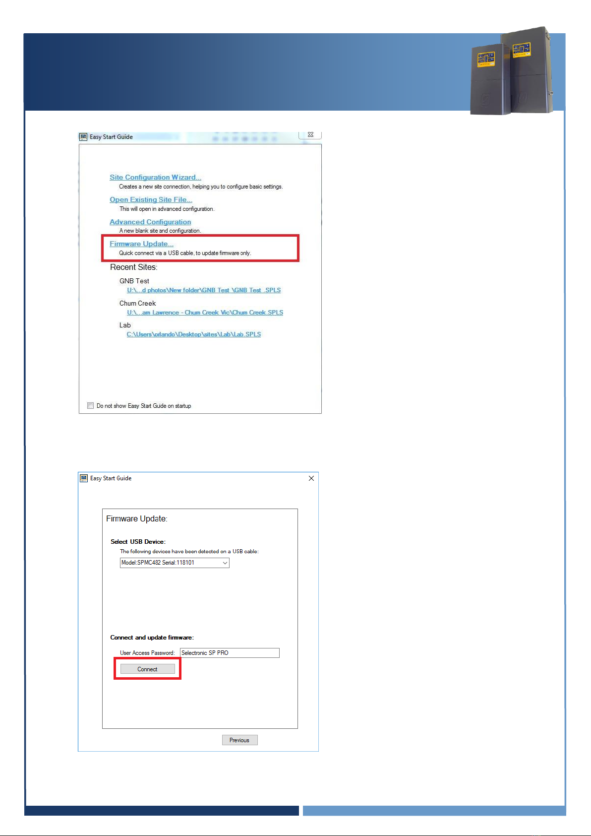
6. At the Easy Start Guide, select “Firmware Update…”
7. The Easy Start Guide will automatically detect when the SP PRO is ON and USB cable is plugged
into the SP PRO and computer.
Click “Connect” to start the SP PRO Firmware Update process.

IN0051 Revision 05 (005293)–6 of 26
POWER PERFORMANCE PASSION
SP PRO Interactive Inverter Charger
Installation Note
8. In the SP PRO Firmware Update screen, click on the Upload firmware and restart SP PRO
on completion button.
Important:
a. Some batteries may turn themselves OFF during the firmware update. If this occurs, turn
the batteries ON, close the SP PRO Firmware Update window and reconnect to the
SP PRO. Continue the firmware update (step 7 and 8), repeat the process until the
firmware is updated.
b. In the case where the SP PRO firmware upload is complete and the batteries turn OFF
while the SP PRO is performing a firmware upgrade, turn the batteries ON and wait until
the front panel LEDs are stable. This may take a few minutes.
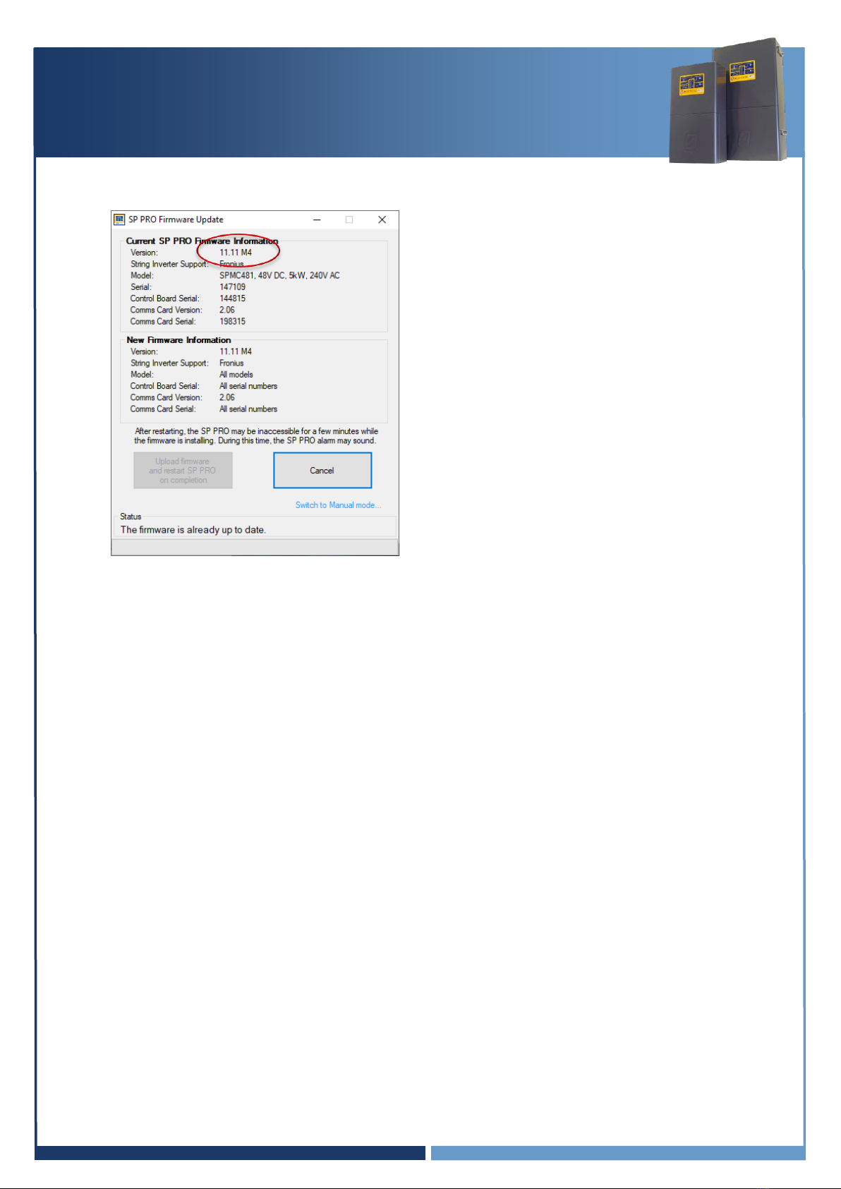
9. Verify the firmware has updated successfully. Once the SP PRO has restarted, wait another 20
seconds then click “Connect” again at the Easy Start Guide.
IN0051 Revision 05 (005293)–7 of 26
POWER PERFORMANCE PASSION
SP PRO Interactive Inverter Charger
Installation Note
10. The “Upload firmware and restart SP PRO on completion” button will now be disabled if the
Current and New versions are the same.
11. Disconnect SP LINK and power down the SP PRO inverter. All Lights on the front panel will be
OFF. The three blue lights across the top will still be lit if there is AC source power (grid or
generator). This is OK.
Continue to section “Installing the Comms Card 2017 (blue or black)” page 8

IN0051 Revision 05 (005293)–8 of 26
POWER PERFORMANCE PASSION
SP PRO Interactive Inverter Charger
Installation Note
Installing the blue or black Comm Card
1. Make sure that the SP PRO inverter is powered down. All Lights on the front panel will be off.
The three blue lights across the top will still be lit if there is AC source power (grid or generator).
This is Ok.
2. Remove the 4 Torx screws holding the original green comm card in the SP PRO.
Do not throw away the Torx screws, the screws will be used to remount the blue or black
Communication Card. (Mounting Screws)
3. Remove the 2 short grey RJ45 connectors from the Control Board in the SP PRO. (Internal
Communications Ports 1 and 2)
4. Remove the white, 2 pin plug on the top right corner of the green comm card (Power)
5. Remove the original green comm card.
6. Connect the white, 2 pin plug to the top, right corner of the blue or black comm card. (Power)
7. Connect the two, small grey RJ45 leads to the blue or black comm card and into the Control
board in the SP PRO. (Internal Communications Ports 1 and 2)
8. Screw down the blue or black comm card into the SP PRO using the 4 Torx screws.
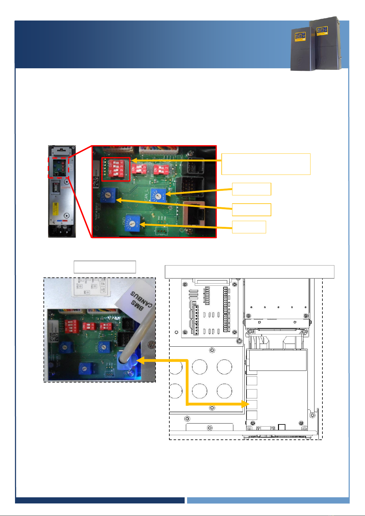
Power
Internal Communications
Port 1 and 2
USB Port
SCERT Comms to
Adaptor board
(J5 RS485-2)
CANBus Battery Comms
RS232 Port 1
Mounting Screws
Mounting Screws

IN0051 Revision 05 (005293)–9 of 26
POWER PERFORMANCE PASSION
SP PRO Interactive Inverter Charger
Installation Note
Communications Connection to SP PRO
The following communication connections must be completed for the appropriate battery type in order
for the system to operate with the SP PRO.
This section outlines the connection process of the communication line for the different battery options
compatible with the SP PRO inverter.
Section 1 for BYD B-Plus, B-Plus 13.8 and B-Plus 15.5 ONLY: Go to page 10
Communication connection for BYD B-Box
Section 2 for Sonnenschein@home Lithium ONLY: Go to page 11
Communication connection for Sonnenschein@home Lithium
Section 3 for LG Chem RESU (Single battery) ONLY: Go to page 12
Communication connection for LG Chem RESU
Section 4 for LG Chem RESU Plus (Dual battery) ONLY: Go to page 13
Communication connection for LG Chem RESU Plus
Section 5 for LG Rack mount modules ONLY: Go to page 14
Communication connection for LG Chem Rack Mount
Section 6 for Pylontech US2000 modules ONLY: Go to page 15
Communication connection for LG Chem Rack Mount
Pinout for the BMS to SP PRO CAN Bus cable
Pinout for BMS to SP PRO cable for the LG Standalone modules (Rack mount).

IN0051 Revision 05 (005293)–10 of 26
POWER PERFORMANCE PASSION
SP PRO Interactive Inverter Charger
Installation Note
Section 1 for BYD B-Plus batteries in a BYD B-Box
1. When installing a Split phase or Three phase system you must connect the pre-charge / battery
sense terminals. The BYD uses the pre-charge function in the SP PRO. ( see “IN0052_xx
Installation of an Advanced Multiphase system” for wiring details.)
2. Leave the battery temperature sensor connected and rolled up inside the SP PRO. This is not
used in a managed battery system.
3. Follow the BYD B-Box instructions to install the BYD B-Box.
4. Using the applicable installation kit, connect the RJ45 Connector cable from the SP PRO blue or
black comm Card “SP PRO CANBUS” to the BYD B-Box “BMS CANBUS”.
Go to section “Check Communications Card Firmware” page 16
SP PRO Inverter (L1 only in a multiphase system)
SP PRO CANBUS
BYD B-Box
blue or black
Comm Card
(Comms Card 2017)

IN0051 Revision 05 (005293)–11 of 26
POWER PERFORMANCE PASSION
SP PRO Interactive Inverter Charger
Installation Note
Section 2 for Sonnenschein@home Lithium
1. Do not connect any wires to the pre-charge / battery sense terminals. The battery sense voltage
is read from the Sonnenschein@home battery BMS.
2. Leave the battery temperature sensor connected and rolled up inside the SP PRO. This is not
used in a managed battery system.
3. Follow the Sonnenschein@home Lithium instructions to install the Sonnenschein@home Lithium.
4. Using the applicable installation kit, connect the RJ45 Connector cable from the SP PRO blue or
black comm card “SP PRO CANBUS” to the Sonnenschein@home Lithium “BMS CANBUS”.
4. Fit two 200A NH fuses (ABB OFAF1H200 or equivalent) for SPMC482 or two 160A NH fuses (ABB
OFAF1H200 or equivalent) for SPMC481 into the fuse housing inside the Sonnenschein@home.
NOTE: The battery fuse size for the SPMC482 when used with a Sonnenschein@home lithium must be
200A. In this application ONLY, do not use the 250A fuses as specified in the SP PRO installation manual
as this may damage the Sonnenschein@home lithium. A 200A fuse is suitable in this application as the
nominal battery voltage for the Sonnenschein@home lithium is 54V.
Go to “Check Communications Card Firmware” page 16
blue or black
Comm Card
SP PRO CANBUS
Sonnenschein@home
SP PRO Inverter (L1 only in a multiphase system)
Fuses inside
IN0051 Revision 05 (005293)–12 of 26
POWER PERFORMANCE PASSION
SP PRO Interactive Inverter Charger
Installation Note
Section 3 for LG RESU (Single battery)
1. The SP PRO battery temperature sensor remains connected to the SP PRO.
Roll it up and place it inside the SP PRO.
2. Do not connect any wires to the pre-charge/battery sense terminals. The battery sense voltage is
read from the RESU BMS.
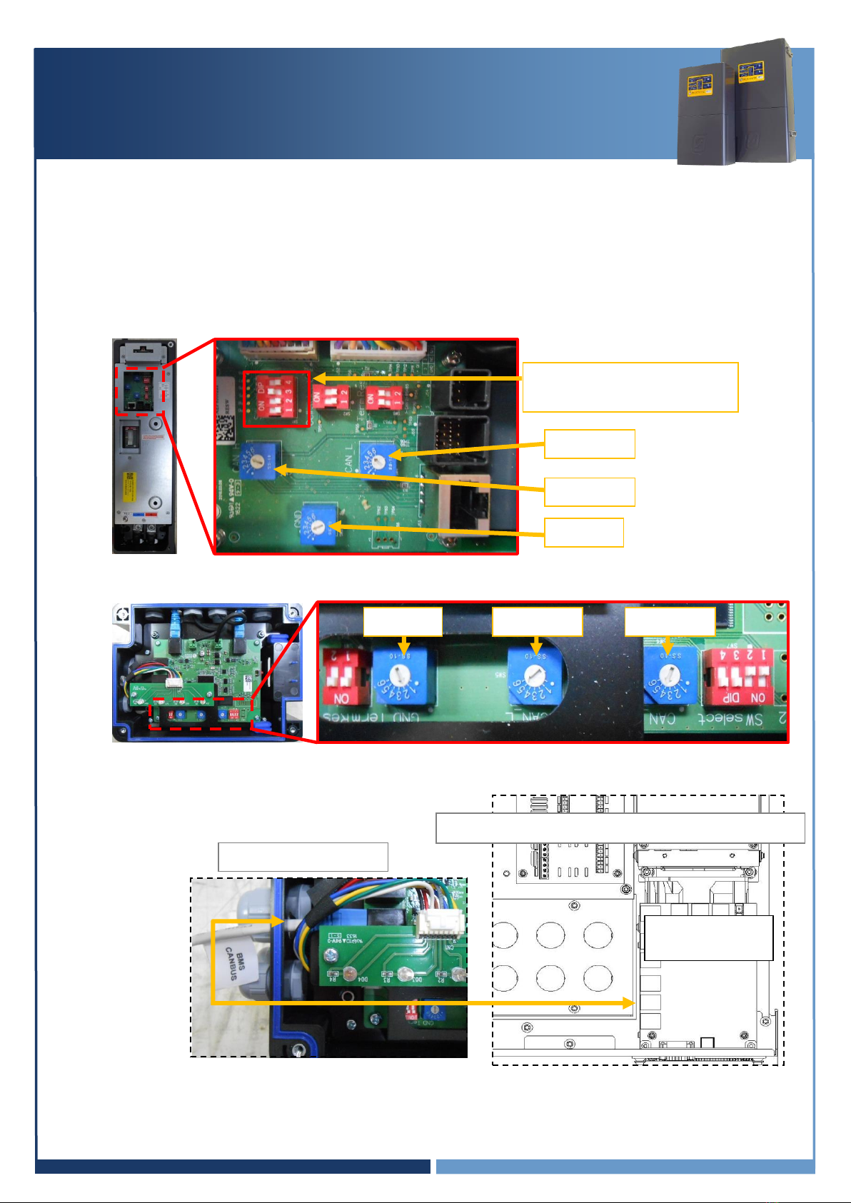
3. Configure the LG Chem RESU dip switch, set “SW Select”: 1&2 = OFF and 3&4 = ON.
4. Configure blue rotary switches, CAN H = 4, CAN L= 5 and GND = 2
5. Using the applicable installation kit, connect the RJ45 Connector cable from the SP PRO blue or
black comm card “SP PRO CANBUS” to the LG Chem RESU “BMS CANBUS”.
Go to section “Check Communications Card Firmware” page 16
blue or black
Comm Card
SP PRO CANBUS
SW Select: 1&2 = OFF
3&4 = ON
LG Chem RESU
SP PRO Inverter (L1 only in a multiphase system)
GND = 2
CAN L = 5
CAN H = 4
IN0051 Revision 05 (005293)–13 of 26
POWER PERFORMANCE PASSION
SP PRO Interactive Inverter Charger
Installation Note
Section 4 for LG Chem RESU Plus (Dual battery)
1. The SP PRO battery temperature sensor remains connected to the SP PRO.
Roll it up and place it inside the SP PRO.
2. Do not connect any wires to the pre-charge/battery sense terminals. The battery sense voltage is
read from the RESU BMS.
3. Follow the RESU instructions to install the RESU plus and the RESU battery banks.
4. Configure the LG Chem RESU dip switch, set “SW Select”: 1,2&4 = OFF and 3 = ON.
6. Configure the LG Chem batteries and the LG Chem RESU Plus blue rotary switches:
CAN H = 4, CAN L= 5 and GND = 2.
5. Using the applicable installation kit, connect the RJ45 Connector cable from the SP PRO blue or
black comm card “SP PRO CANBUS” to the LG RESU “BMS CANBUS”.
Go to section “Check Communications Card Firmware” page 16
SW Select: 1,2&4 = OFF
3 = ON
CAN L = 5
CAN H = 4
blue or black
Comm Card
SP PRO CANBUS
SP PRO Inverter (L1 only in a multiphase system)
GND = 2
CAN L = 5
GND = 2
LG Chem RESU Plus
CAN H = 4
IN0051 Revision 05 (005293)–14 of 26
POWER PERFORMANCE PASSION
SP PRO Interactive Inverter Charger
Installation Note
Section 5 for LG Chem Rack Mount Modules
1. Do not connect any wires to the pre-charge or battery sense terminals. The battery sense
voltage is read from the LG Chem Rack Mount BMS.
2. Follow the LG Chem Rack Mount instructions to install the LG Rack Mount.
3. Using the applicable installation kit, connect the RJ45 end of the cable to the SP PRO blue or
black comm card “SP PRO CANBUS” and connect the DB9 end to the LG Chem Rack Mount
battery DB9 cable “BMS CANBUS”.
Go to section “Check Communications Card Firmware” page 16
blue or black
Comm Card
SP PRO CANBUS
LG Chem Rack Mount
SP PRO Inverter (L1 only in a multiphase system)
IN0051 Revision 05 (005293)–15 of 26
POWER PERFORMANCE PASSION
SP PRO Interactive Inverter Charger
Installation Note
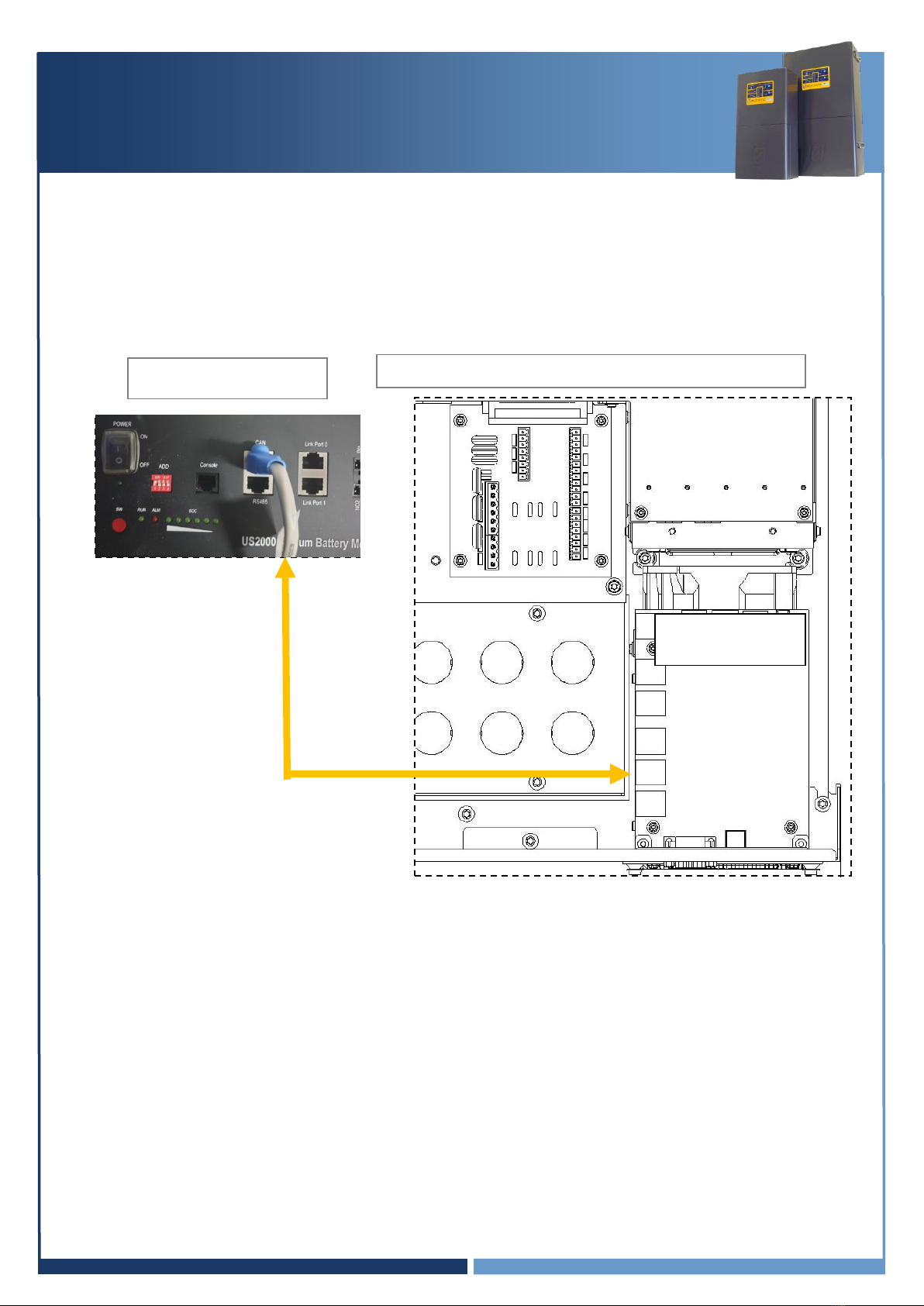
Section 6 for Pylontech US2000 modules
1. Leave the battery temperature sensor connected and rolled up inside the SP PRO. This is not
used in a managed battery system.
2. Follow the Pylontech instructions to install the modules.
3. Using the applicable installation kit, connect the RJ45 Connector cable from the SP PRO blue or
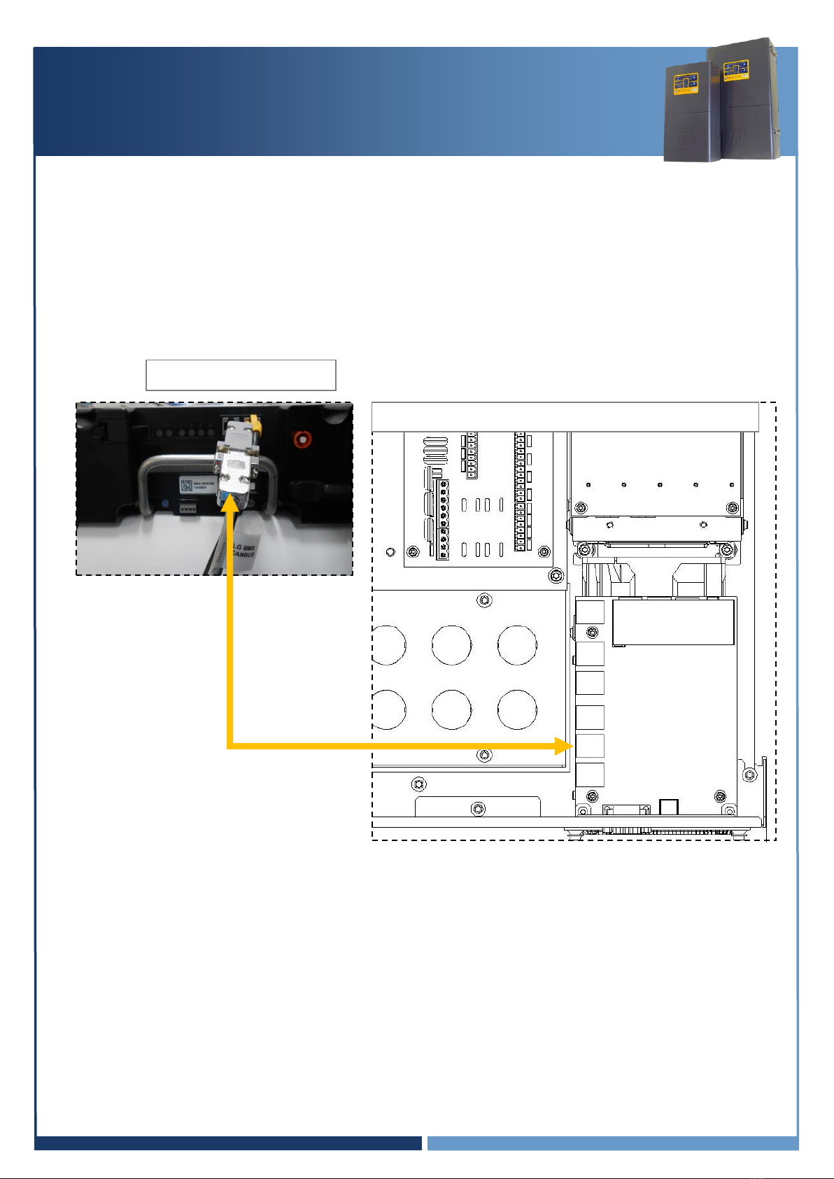
black comm Card “SP PRO CANBUS” to the Pylontech module “BMS CANBUS”.
Go to section “Check Communications Card Firmware” page 16
SP PRO
SP PRO CANBUS
Pylontech US2000
blue or black
Comm Card
(Comms Card 2017)

IN0051 Revision 05 (005293)–16 of 26
POWER PERFORMANCE PASSION
SP PRO Interactive Inverter Charger
Installation Note
Check Communications Card Firmware
The Communication Card firmware must be 2.06 or higher.
A Communication Card with firmware 0.05 or higher can be updated using SP LINK.
To check and update the firmware if required, follow the steps below:
Note: Each battery type has a different power ON procedure. If the correct procedure for a given
battery type is not followed, the battery may not turn ON and run.
1. Connect the DC power to the SP PRO. This is done as follows:
For Sonnenschein@home –Leave the system DC circuit breaker or fuses OFF and turn
the battery ON by pressing the ON button (adjacent to the fuse holder). When the relay
inside the battery clicks, indicating the batteries have come ON, turn ON the system DC
breaker or fuses.
For LG Chem RESU –Turn ON the system DC breaker or fuses to the SP PRO then turn
ON the battery bank circuit breaker(s).
For Pylontech US2000 –Turn ON the battery by switching the On/Off switch to the ON
position.
For BYD B-Plus 2.5 modules, BYD B-Plus 13.8 BYD B-Plus 15.5, turn ON the battery bank
by pressing the ON button. Turn on the Pre-charge / Battery Sense (If the system is AMP)
and wait until the SP PRO comes on, then turn on the Battery Breaker or switch.
For LG Chem Rack Mount –Turn ON the system DC breaker or fuses to the SP PRO then
turn ON the battery bank by pressing the ON button.
Wait until the front panel LEDs are stable.
NOTE:
a. During the SP PRO power up, the front panel display cycles through three stages. First, all LEDs turn
green from bottom up, second, all LEDs turn red from bottom up and third, some LED’s will be flashing
while the battery LEDs are ON solid green. The third stage is what is referred to as stable.
b. Perform the following tasks quickly as the batteries might shutdown in 5-10 minutes without the
CANBUS communications. If this happens, turn the batteries ON and restart the process.
2. After the SP PRO has powered up and the front panel LEDs are stable, check the green LEDs on
the blue or black comm card.
The right LED should be steadily ON.
The left LED should be ON or flash approximately once per second.
3. Start Selectronic SP LINK.
1
2
IN0051 Revision 05 (005293)–17 of 26
POWER PERFORMANCE PASSION
SP PRO Interactive Inverter Charger
Installation Note
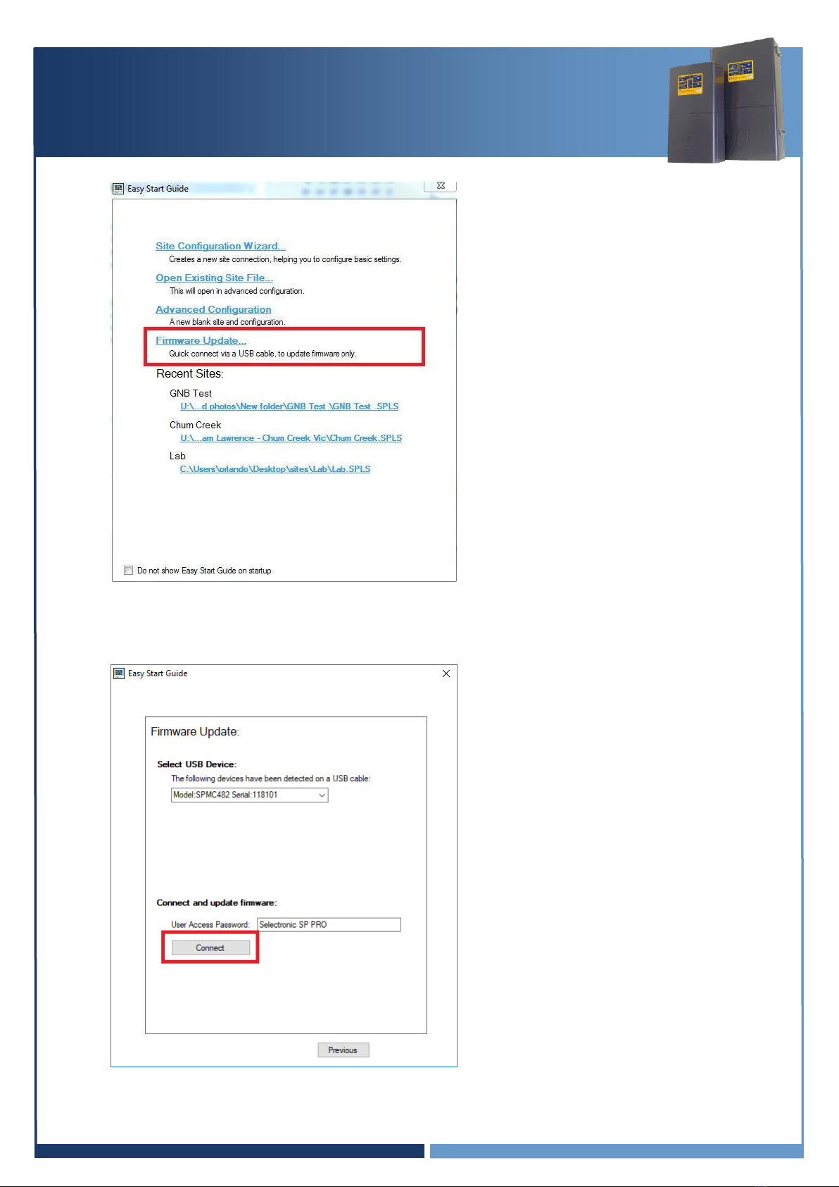
4. Select “Firmware Update…”
5. The Easy Start Guide will automatically detect when the SP PRO is ON and USB cable is plugged
into SP PRO and computer.
Click “Connect” to start the firmware update process.
IN0051 Revision 05 (005293)–18 of 26
POWER PERFORMANCE PASSION
SP PRO Interactive Inverter Charger
Installation Note
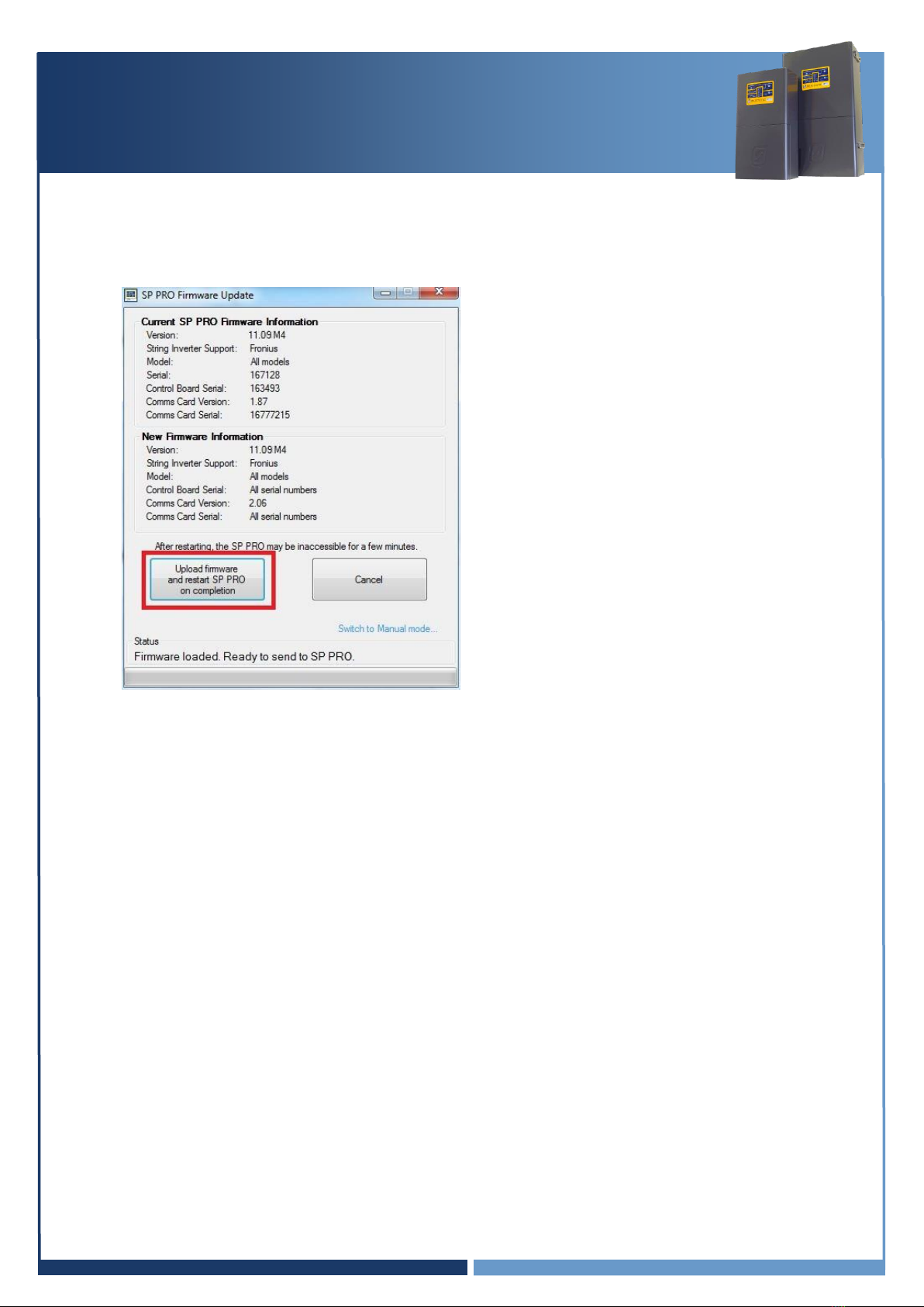
6. In the SP PRO Firmware update screen click on the Upload firmware and restart SP PRO on
completion button.
Note: If firmware is already up to date then this button will be disabled. Continue to
“SP PRO Configuration” on page 19
Important:
a. Batteries may turn OFF during the firmware update. If this occurs, turn the batteries ON,
close the SP PRO Firmware Update window.
Reconnect to the SP PRO and continue Firmware update (step 7 and 8). Repeat the
process until the firmware is updated.
b. In the case where the SP PRO firmware upload is complete and the batteries turn OFF
while the SP PRO is performing a firmware upgrade, turn the batteries ON and wait until
the front panel LEDs are stable. This may take a few minutes.
7. After the update is completed, the SP PRO will automatically restart. You will need to wait about
2.5 minutes for the blue or black comm card to restart. Communications with the SP PRO will
be lost during this time.

IN0051 Revision 05 (005293)–19 of 26
POWER PERFORMANCE PASSION
SP PRO Interactive Inverter Charger
Installation Note
8. Verify the firmware has updated successfully. Once the SP PRO has restarted, wait another 20
seconds then click “Connect” again at the Easy Start Guide.
9. Make sure the Current “Comms Card Version” is 2.06 or higher, and matching the New version.
Note: If the blue or black comm card Firmware is up to date then the “Upload firmware and
restart SP PRO on completion” button will be disabled.
Note: The blue or black comm
card info will be displayed on the
screen.
IN0051 Revision 05 (005293)–20 of 26
POWER PERFORMANCE PASSION
SP PRO Interactive Inverter Charger
Installation Note
SP PRO Configuration
1. Make sure the USB lead is connected between the SP PRO and PC.
2. Make sure the DC power is present at the SP PRO.
If NOT then connect the DC power to the SP PRO as follows:
For Sonnenschein@home –Leave the system DC circuit breaker or fuses OFF and turn
the battery ON by pressing the ON button (adjacent to the fuse holder). When the relay
inside the battery clicks indicating the batteries have come ON, turn ON the system DC
breaker or fuses.
For LG RESU –Turn ON the system DC breaker of fuses to the SP PRO then turn ON the
battery bank circuit breaker(s).
For BYD B-Plus 2.5 modules, BYD B-Plus 13.8 BYD B-Plus 15.5, turn ON the battery bank
by pressing the ON button. Turn on the Pre-charge / Battery Sense (If the system is AMP)
and wait until the SP PRO comes on, then turn on the Battery Breaker or switch.
For LG Chem Rack Mount –Turn ON the system DC breaker or fuses to the SP PRO then
turn ON the battery bank by pressing the ON button.
Wait until the front panel LEDs are stable.
NOTE:
a. During the SP PRO power up, the front panel display cycles through three stages. First, all
LEDs turn green from bottom up, second, all LEDs turn red from bottom up and third, some
LED’s will be flashing while the battery LEDs are ON solid green. The third stage is what is
referred to as stable.
b. Perform the following tasks quickly as the batteries might shutdown in 5-10 minutes without
the CANBUS communications. If this happens, turn the batteries ON and restart the process.
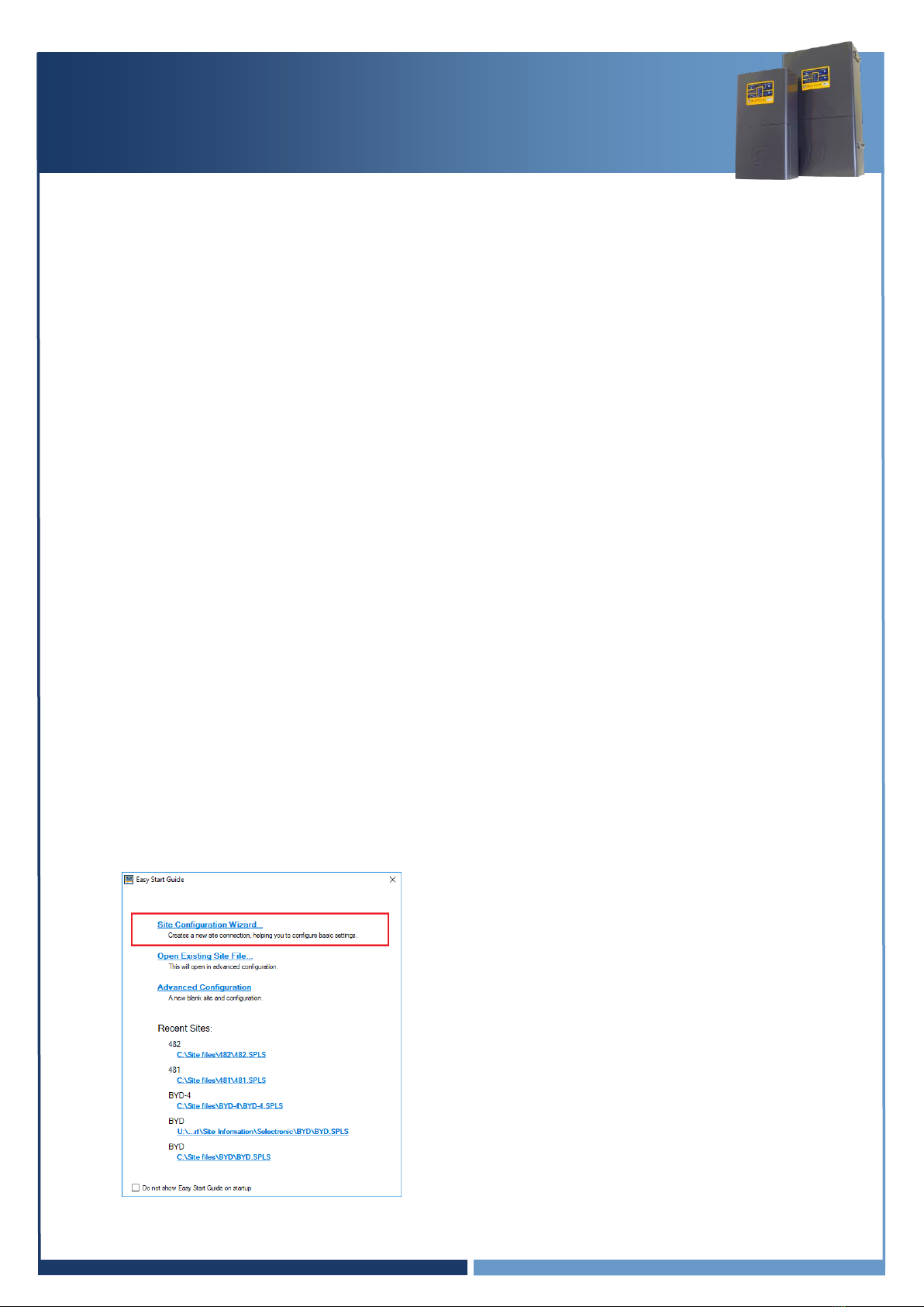
3. Start Selectronic SP LINK.
4. Select “Site Configuration Wizard”
Other manuals for SP PRO
9
Table of contents
Other Selectronic Batteries Charger manuals


