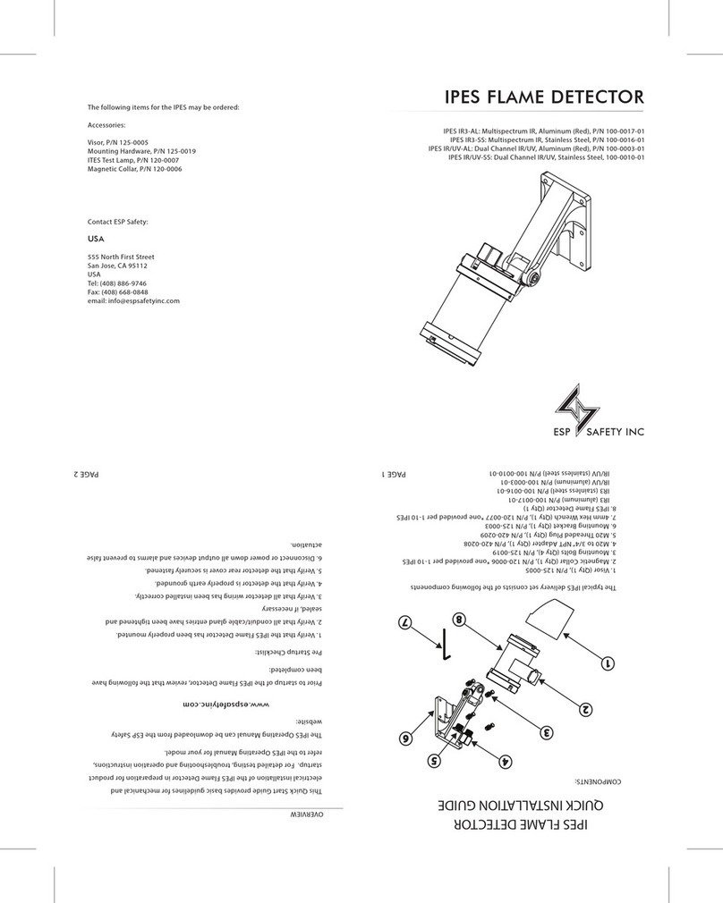
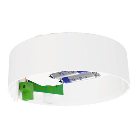
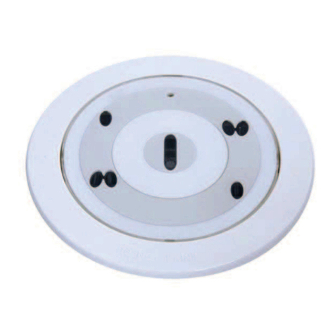
ESP Safety IPES-IR/UV User manual

IPES-IR/UV Flame Detector
Operating Manual
80010-001 R07


IPES-IR/UV Flame Detector
Operating Manual
80010-001 R07
ESPSafety,Inc.
555NorthFirstStreet
SanJose,CA95112
408‐886‐9746
March2013
RevisionHistory:80010‐001
DateRevisionDescriptionApproved
12/09/0901InitialDraftJ.Lorelli
1/10/1002TechnicalcontentreformattedJ.Lorelli
3/12/1003Corrections;FMchangesJ.Lorelli
3/30/1004Corrections;RevT5markingK.Bernstein
2/22/1105IECEx/ATEXrevisionsK.Bernstein
4/4/1206CorrectionsYaroslavMiloserdov
3/21/1307Addition;AppendixCWarranty&
ReturnPolicy
A. Burgos

IPES-IR/UV Flame Detector
80010-001 R07 Operating Manual
Page ii
Revised 10/21/2013
TableofContents
1.0Introduction......................................................................................................................................................................1
OurMission...............................................................................................................................................................................1
ESPSafetyIncContactInformation..........................................................................................................................................1
2.0Description........................................................................................................................................................................2
Application................................................................................................................................................................................2
Specifications............................................................................................................................................................................2
3.0SafetyConsiderations........................................................................................................................................................3
Guidelines.................................................................................................................................................................................3
ExplosionProtectionMeans.....................................................................................................................................................3
AdditionalConsiderations.........................................................................................................................................................4
FMCompliance.......................................................................................................................................................................4
IPES‐IR/UV.................................................................................................................................................................................4
4.0PerformanceCharacteristics..............................................................................................................................................6
Appearance...............................................................................................................................................................................7
ResponseTime..........................................................................................................................................................................7
GenerationofAlarmSignals.....................................................................................................................................................7
EliminationofFalseAlarms.......................................................................................................................................................7
Serviceability.............................................................................................................................................................................8
LED............................................................................................................................................................................................8
OpticalIntegrity........................................................................................................................................................................8
AnalogSignal...........................................................................................................................................................................10
DigitalSignal...........................................................................................................................................................................10
RelayDryContactSignal.........................................................................................................................................................10
OperatingModes....................................................................................................................................................................10
5.0Installation.......................................................................................................................................................................11
ComponentPartsandDeliverySet.........................................................................................................................................11
VisualExamination..................................................................................................................................................................11
Pre‐InstallationSteps..............................................................................................................................................................11
Installation..............................................................................................................................................................................11
CompletingtheInstallation.....................................................................................................................................................19
ArrangementandFunctionofMountingConnectionTerminals............................................................................................14
6.0StartupandOperation......................................................................................................................................................16
Startup........................................................................................................................................Error!Bookmarknotdefined.
Operation................................................................................................................................................................................18
7.0Troubleshooting...............................................................................................................................................................18
TroubleshootingTable............................................................................................................................................................18
8.0Maintenance....................................................................................................................................................................19

IPES-IR/UV Flame Detector
80010-001 R07 Operating Manual
Page iii
Revised 10/21/2013
MaintenanceActivities...........................................................................................................................................................19
DailyMaintenance..................................................................................................................................................................19
EverySixMonths.....................................................................................................................................................................20
AutomaticTesting...................................................................................................................................................................20
9.0TransportationandStorage..............................................................................................................................................20
Transportation........................................................................................................................................................................20
Storage....................................................................................................................................................................................20
10.0Warranties......................................................................................................................................................................21
ExpectedServiceLifeofUnit..................................................................................................................................................21
11.0RepairandReturn...........................................................................................................................................................22
FieldRepair.............................................................................................................................................................................22
ReturnMaterialAuthorization(RMA)Number.......................................................................................................................22
12.0PartsOrderingInformation.............................................................................................................................................22
13.0Certifications..................................................................................................................................................................23
FM(U.S.&Canada).................................................................................................................................................................23
HazardousLocations...............................................................................................................................................................23
ABS..........................................................................................................................................................................................23
ATEX/......................................................................................................................................................................................23
CE............................................................................................................................................................................................23
IEC/.........................................................................................................................................................................................23
IECEx.......................................................................................................................................................................................24
IngressProtection...................................................................................................................................................................24
AppendixA1:IPES‐IR/UVExplosionProtectionMeans...........................................................................................................25
AppendixA‐2:IPES‐IR/UVInstallation....................................................................................................................................26
AppendixB:IPESDigitalCommunicationsProtocol................................................................................................................28
IPESCommands......................................................................................................................................................................28
SettingAddress/BaudRateCommand...................................................................................................................................28
PollStatusCommand..............................................................................................................................................................29
Itisimportantthatthisentiremanualbethoroughlyreadand
understoodpriortoinstallingoroperatingtheIPES‐IR/UV.Any
deviationfromtherecommendationsinthismanualmayimpair
systemperformanceandcompromisesafety.


IPES-IR/UV Flame Detector
80010-001 R07 Operating Manual
Page 1 of 29
Revised 10/21/2013
1.0Introduction
IntroductionTheIPES‐IR/UVflamedetector’sadvanceddetectiontechnologyincorporatesoptical
filtersconfiguredformaximumsensitivitytoradiationproducedbyflameorfireand
ensuresrapidflamerecognitionandalarmsignaling.TheIPES‐IR/UVhasafieldofview
ofnotlessthan90degrees.Uponfirerecognition,itsignalsachangeinstatefrom
normaloperationtofireinanyoriginalequipmentmanufacturersOEMorproprietary
alarmandresponsesystem.
Viaintegratedinfrared(IR)andultraviolet(UV)sensorstheIPES‐IR/UVmonitorsin
specificregionsofbothspectralranges.Intheinfraredspectrum,thedeviceis
configuredforsensitivitytowavelengthsintherangeof4.2to4.6microns,allowing
optimalsensitivitytohydrocarbonfires,andothertypessuchasmetalfireswhile
rejectingfalsesignalsfromincandescentlamps,sunlightandhotobjects.Forultraviolet
radiation,thedeviceisconfiguredforsensitivityintherangeof180to250nanometers,
makingthesensor“blind”tosunlightandradiationfromheatedobjectsbutstillableto
“see”theUVradiationemittedbyaflame.Withthesesettings,theIPES‐IR/UVselects
andalarmsfromthosecharacteristicwavelengthemissionsfromtheIR‐to‐UVspectrum
thatindicateactualflameorfire.
ThecombinationofmultiplesensorsandwavelengthrangesettingsmakestheIPES‐
IR/UVanexcellentchoiceforeliminationoffalsepositiveindicatorscausedbynon‐flame
sourcesofradiationsuchasartificiallighting,directandindirectsunlight,lightning,arc
weldingandmetalgrinding.
OurMissionESPSafety,Inc.’smissionistoprovidecompleteturn‐keyprotectionsolutionsbeginning
withthedesignstage,throughsysteminstallationandcommissioning,andon‐goingfield
serviceinhazardousenvironments.Ourlineofindustry‐leadingproducts,services,and
systemsbenefitssociety,saveslives,andpreservescapitalresources.
ESPSafety,Inc.Contact
Information
Telephone:408‐886‐9746
FAX:408‐886‐9757
Address:555NorthFirstStreet,SanJose,CA95112

IPES-IR/UV Flame Detector
80010-001 R07 Operating Manual
Page 2 of 29
Revised 10/21/2013
2.0Description
ApplicationTheIPES‐IR/UV’sdesignandexplosion‐proofratingsmakeitanexcellentchoicefor
indoorandoutdoorapplications,including:
Drillingandproductionplatforms
Shippingtankers,freighters,andothervessels
Fuelloadingfacilities
Refineries,bulkterminals,andtankfarms
LNG/LPGprocessingandstoragefacilities
Compressorstationsandpipelinefacilities
Petrochemical,paint,andfertilizerplants
Powerplantsandgasturbinefacilities
Transportationfacilities(airportsandsubways)
Oilandgasfiredboilers/furnaces
Aircrafthangars
SpecificationsTheIPES‐IR/UVmeetsindustrycertificationsandrequirementsforHazardousLocations.
DetectionType:Optical
DetectionMethod:IRandUVradiation
SpectralRange:4.2to4.6micron(IR);180to250nm(UV)
PowerSupply:18to32VDC
PowerConsumption:StandBy:2Wmax;AlarmState:3Wmax
FireRelayOutputs:Singlepolecontact,normallyopen,rated5A@30VDC;normally
closedcontactisavailableonrequest*
*NormallyclosedconfigurationisnotcompliantwithNFPA72,ULC/ORD–C386and
FM.
FaultRelayOutputs:Singlepolecontact,normallyopen,rated5A@30VDC;closedin
normalwork,openonfaultdetectionorlossofpower
Communications:
Analogoutput:4‐20mA
Digitalsignal:RS‐485withModbusprotocol
Wiring:14AWG(2.08mm2)or16AWG(1.31mm2).Shieldedcableisrecommended.
OperatingTemperature:‐40°Fto+185°F(‐40°Cto+85°C)
StorageTemperature:‐76°Fto+185°F(‐60°Cto+85°C)
Humidity:95%,non‐condensing
HazardousLocationClassification:Pleaserefertosection13.0Certifications

IPES-IR/UV Flame Detector
80010-001 R07 Operating Manual
Page 3 of 29
Revised 10/21/2013
ConduitEntry:¾”NPTapprovedHazLocbushing
EnclosureMaterials:316SSor6061Aluminum
EnclosureScrews:Pleaserefertosection13.0Certifications
Weight:SS=11lbs(5.0kg);Aluminum=5.5lbs(2.5kg)
3.0SafetyConsiderations
BeforeinstallingandoperatingtheIPES‐IR/UV,besuretoread
thisentiremanual.Failuretofollowtheseguidelinescouldresult
inimpairedproductperformanceandsafetyhazards.
GuidelinesFormaximumsafety:
Onlypersonswhohavethoroughlyreadandunderstoodthismanual,aretrainedin
safetytechniques,andhaveelectric‐safetycertificatesarepermittedtoinstalland
operatetheIPES‐IR/UV.
NeveroperatetheIPES‐IR/UVifthecasingisdamaged.
DonotseparatetheIPES‐IR/UVwhenenergized.
RefertotheAppendicesanddiagramsinthismanualtoensurethatthewiringisin
compliancewithlocalordinancesandtheNEC.
PerformregulartestingandmaintenanceasoutlinedintheMaintenancesection.
Ensurethatfire‐alarmandfire‐extinguishingsystemsandcontrolsareswitchedoff
beforeanytestingormaintenancetoavoidunwantedoperationofalarmsandfire‐
extinguishingequipment.
Alsoseetheindividualsectionsinthismanualforrelevantspecificsafetyguidelines.
ExplosionProtection
Means
ThetablebelowdescribesdesignfeaturesthatprotecttheIPES‐IR/UVagainstexplosions:
FeatureProtectionMeans
EnclosureofCurrent
CarryingParts
Thecasingincludesspigotjointswithcontrolledgapstomeet
explosion‐proofrequirementsforinstallationinClassI,DivisionI,
GroupB,CandD,andT5locations.
CaseMechanicalStrengthThehighmechanicalstrengthofthecaseisabletowithstandhigh
explosivepressureswithoutruptureorfailuresofmechanicalparts.
ThecasedesignisinaccordancewithFM3600andFM3615.
ManufacturingControlOf
Casing
RefertoAppendixA1formanufacturingdetails.Important
parametersinclude:
Maximumwidthandminimumlengthofspigotjoints
Surfaceroughnessofthejoinedparts
Thenumberofcompleteintactthreadsattheconduitentry
point

IPES-IR/UV Flame Detector
80010-001 R07 Operating Manual
Page 4 of 29
Revised 10/21/2013
FeatureProtectionMeans
IgnitionTemperatureTheignitiontemperatureofthesurroundingenvironmentislimited
bytheoutsidesurfacetemperatureofthehousing,whichdoesnot
exceed275°F(135°C).
SecuringofBolts,Joints
andGrounding
Springwashers,lockwashers,andlocknutsmaintaintheintegrityof
theboltedconnectionsbypreventinglooseningofthebolts.
JoinedPartsProtectionAnti‐seizelubricantisappliedonthecriticaljointsasdescribedon
AppendixA1.
CasingIngressProtectionThedesignofthecasingisprotectionclassIP66inaccordancewith
IEC60529‐004.
SealingCablesatConduit
Entry
Useapprovedhazardouslocationsealedconduitfittings.Foroutdoor
installations,ensuresealingmeetsIP66requirements.
Additional
Considerations
Itisimportanttoidentifyfalsealarmsourcesandanyconditionsthatcouldpreventthe
IPES‐IR/UVfromrespondingappropriatelytoafire.Thefollowingshouldbeconsidered:
FalseAlarm
Prevention
ArcWeldingandGasWelding
DonotperformarcorgasweldingwithinthefieldofviewoftheIPES‐IR/UV.Systembypass
ismandatoryforgasweldingandishighlyrecommendedforallweldingactivity.Referto
thesectiononFMCompliancebelowforresultsoftestingwithfalsestimuli.
Walkie‐Talkies
OwingtopotentialEMIandRFIinterference,walkie‐talkiesshouldnotbeusedwithin1foot
oftheIPES‐IR/UV.
FireTypesTheIPES‐IR/UVcandetecthydrocarbonfiresfrompetrochemicalsources,metalfires,and
firesfromwoodandpaperproducts.Inaddition,thedetectorisFM‐approvedfordetecting
methane,propane,n‐Heptane,JP4,andmethanolfires.
FMCompliance
IPES‐IR/UVMeetsFM(USandCanada)certificationsandrequirementsforHazardousLocation
classification:ClassI,DivisionI,GroupB,CandDandT5CasedesignaccordswithFM3600
andFM3615.Ta=‐40oCto+85oC(‐40oFto+185oF)IP66

IPES-IR/UV Flame Detector
80010-001 R07 Operating Manual
Page 5 of 29
Revised 10/21/2013
Standards
FlameResponse
Sensitivity
TITLEAUTHOR‐NUMBERDATE
NationalFireAlarmCodeANSI/NFPA722002
RadiantEnergy‐SensingFire
DetectorsforAutomaticFire
AlarmSignaling
ANSI/FM‐32602004
RadiantEnergy‐SensingFire
DetectorsforAutomaticFire
AlarmSignaling
FMApprovals‐32602000
ElectricalEquipmentForUseIn
Hazardous(Classified)Locations–
GeneralRequirements
FMApprovals–36001998
ExplosionproofElectrical
Equipment–General
Requirements
FMApprovals–36152006
FlameDetectorsULC/ORD‐C3861990
StandardforSmokeDetectorsfor
FireAlarmSystems
CAN/ULC‐S5292002
ThreadedConduitEntriesCSAC22.2No.0.5
(Reaffirmed)
1982
(1999)
Explosion‐ProofEnclosuresfor
UseinClassIHazardousLocations
CSAC22.2No.30
(Reaffirmed)
1986
(2003)
DegreesofProtectionProvidedby
Enclosures(IPCode)
ANSI/IEC60529
CSA‐C22.2No.60529
2004
2005
ExplosiveAtmospheres,General
Requirements
ANSI/ISA60079‐02009
ExplosiveAtmospheres,
Equipmentprotectionby
flameproof“d”enclosures
ANSI/ISA60079‐12009
WhenanIPES‐IR/UVdetectorisexposedtoaseriesoftestfiresalongthecenterlineofthe
sensorasdescribedinthetablebelow,thealarmresponseoftheIPES‐IR/UVisbelowthe
30‐secondresponsetimerequiredunderFMStandard3260.
FuelDistanceFireSizeAverageTime
n‐Heptane82ft.(25m.)1ft.x1ft.(32.5cm.)pan4.52sec.
Denaturedethyl
alcohol(85.4%)
82ft.(25m.)1ft.x1ft.(32.5cm.)4.9sec.
JP482ft.(25m.)2ft.x2ft.(60cm.)panInstantaneously

IPES-IR/UV Flame Detector
80010-001 R07 Operating Manual
Page 6 of 29
Revised 10/21/2013
FalseStimuli
Exposure
WhentheIPES‐IR/UVisexposedtothefiresspecifiedabove,andareinthepresenceofthe
followingfalsestimulisources–modulatedatapproximately1.5Hz,andun‐modulated–no
falsealarmactivationorinstabilityoccursattheminimumdistanceslistedbelow.
SourceDistance
Heater12inches(30.48cm.)
Arcwelder9.8feet(3m.)
Fluorescent6inches(15.24cm.)
Halogen6inches(15.24cm.)
Incandescent6inches(15.24cm.)
DirectsunlightDetectorsnotaffectedbyfrequencyrangeof
visiblelight
IndirectsunlightDetectorsnotaffectedbyfrequencyrangeof
visiblelight
FieldofViewTheIPES‐IR/UV’sviewingangleisvariedfromthecenterlineup,down,leftandright.The
detectorisexposedtoeachofthetestfiresdescribedin“FlameResponseSensitivity”above
atadistancedescribedinthetablebelow.
FuelHorizontal
(Left)
Horizontal
(Right)
Vertical
(Up)
Vertical
(Down)
Min,
Distance
Avg.Time
n‐Heptane45o45o45o45o56.1ft.(17.1
m.)4.61sec.
Denaturedethyl
alcohol85.4%45o45o45o45o41ft.(12.5
m.)4.55sec.
JP445o45o45o45o82ft.
(25m.)Instantaneously
4.0PerformanceCharacteristics
AppearanceTheIPES‐IR/UVconsistsofanexplosion‐proofcasingcontainingsensorswhichconvert
EarthGroundAttachmentPoint
MountingBase
OpticalWindowwithIR
&UVDetectors&
OperationalStatusLEDs
FrontCover
RearCover(removefor
wireinstallation)
Figure 4
-
1: Appearance of the IPES
-
IR/UV
Tilt&PanSwivelAdjustments

IPES-IR/UV Flame Detector
80010-001 R07 Operating Manual
Page 7 of 29
Revised 10/21/2013
electromagneticradiationfromflamesintoelectricalsignalsbyuseofelectronicamplifiers
andfilters,digital‐analogconverters,amicroprocessor,andLEDindicators.
ResponseTimeTheIPES‐IR/UVresponsetimetodetectingradiationemittedbytestsourcesofn‐Heptane
combustionina12”x12”(0.3mby0.3m)pan,andethylalcoholcombustionina12”x12”
(0.3mby0.3m)pan,atadistanceof82feet(25meters)doesnotexceed30seconds.
ThesensitivityandresponsetimecanbevariedinordertoreducethenoisewhentheIPES‐
IR/UVidentifiesafire,orthedistancetotheprobableplaceoffireisshort(“near/far”and
“slow/fast”modes).CanbesetusingtheESPCommanderprogram.
GenerationofAlarm
Signals
TheIPES‐IR/UVincorporatesopticalfiltersconfiguredformaximumsensitivitytoradiation
producedbyflameorfire,ensuringrapidflamerecognitionandalarmsignaling.Uponfire
recognitionwithinits90‐degreefieldofview,theIPES‐IR/UVsignalsachangeinstatefrom
normaltofireinanyOriginalEquipmentManufacturers(OEM)orproprietaryalarmand
responsesystem.
Inaddition,viaintegratedinfrared(IR)andultraviolet(UV)sensors,theIPES‐IR/UVmonitors
inspecificregionsofbothspectralranges.Intheinfraredspectrum,thedeviceisconfigured
forsensitivitytowavelengthsintherangeof4.2to4.6microns,allowingoptimalsensitivityto
combustiblegasfireswhilerejectingfalsesignalsfromincandescentlamps,sunlightandhot
objects.Forultravioletradiation,thedeviceisconfiguredforsensitivitytowavelengthsinthe
rangeof180to250nanometers,makingthesensor“blind”tosunlightandradiationfrom
heatedobjectsbutstillableto“see”theUVradiationemittedbyaflame.Withthesesettings,
theIPES‐IR/UVselectsandalarmsfromthosecharacteristicwavelengthemissionsfromtheIR‐
to‐UVspectrumthatindicateactualflameorfire.
Theanalogsignalsfromthesensorsarefiltered,amplified,andthenconvertedtodigital
signalswhicharethenprocessedinamicrocontrollerviaaspecialalgorithm.Thisensuresthe
reliabilityofthealarmsignals.
TheIPES–IR/UVtakesthefollowingparametersintoconsiderationwhengeneratinganalarm
signal:
Magnitudeofsignalsfromdifferentopticalchannels
Ratiosbetweenthesignalamplitudesofdifferentchannels
Signalmodulationfrequency
Phaserelationshipsamongthechannels

IPES-IR/UV Flame Detector
80010-001 R07 Operating Manual
Page 8 of 29
Revised 10/21/2013
EliminationofFalse
Alarms
ThecombinationofmultiplesensorsandwavelengthrangesettingsmakestheIPES‐IR/UVan
excellentchoiceforeliminationoffalsepositiveindicatorscausedbynon‐flamesourcesof
radiationsuchasartificiallighting,directandindirectsunlight,lightning,arcweldingand
metalgrinding.
Seeadditionalimportantconsiderationsforeliminatingfalsealarmsinsection3.0Safety.
AnAlarmconditionwillnormallyoverrideaFaultconditionunlessalossofoperatingpower
impairsthedetector’sabilitytogenerateormaintainanalarm.TheIPES‐IR/UVreportsboth
FaultandAlarmconditionsexclusiveofeachother.ThismeansbothaFireandFaultcanbe
reportedatthesametimeiftheyoccursimultaneously.
Serviceability
TheIPES‐IR/UVremainsserviceableinnon‐heatedroomsorundershedsattemperatures
from–40°Fto+185°F(–40°to+85°C).
LEDNormal,FireandFaultconditionsareindicatedbytworedLEDslocatedonthecover.Referto
Table4‐1:DeterminingLEDConditions,below.
OpticalIntegrityTomaintainreliabilityoftheIPES,theopticaldevicesareautomaticallyself‐testedfor
radiationtransmissionevery25to45minutes.Thisroutinetestdoesnotrequiretheuseofa
testlamp.Thistestdetermineswhetheranydustorothercontaminationhasformedonthe
detectingwindowswhichwouldscattertheinfraredradiation.
UVLEDINDICATOR
IRLEDINDICATOR
UVDETECTOR
IRDETECTOR
Figure 4-2: IR & UV Detectors and LED Indicators

Page 9 of 29 Revised 10/21/2012
Table4‐1:DeterminingLEDConditions
Aftercompletingallinstallationsteps,refertotheillustrationandLEDindicatortablebelowtodetermineLEDconditions.
NIPESstatusFirerelaydrycontactsconditionFault
relaydry
contacts
condition
Output
signal,mA
IndicatorLEDcondition
NormallyclosedNormallyopen
1Nopowersupply
voltage
Closedopenopen0Off
2Faultoroptical
interference(dust)
Closedopenopen2Every25to45secondstwoLEDsblinkwiththefollowing
frequencies:thefirstLEDblinks5timeswithaperiodof0.5seconds,
thesecondoneblinks3timeswithaperiodof1second.BothLEDs
areoffduringthepausebetweenblinking.
3Normal(nofaultsor
firesduringoperation)
Closedopenclosed4Whennoradiationispresent:
Every25to40secondsthetwoLEDsblinkalternately3timeswitha
periodof1second.BothLEDsareoffduringthepausebetween
blinking.
WhenonlyIRradiationispresent:
TheIRLEDindicator(seefigure4‐2)willbeoncontinuously,theUV
LEDindicatorwillbeoff.
WhenonlyUVradiationispresent:
TheUVLEDindicator(seefigure4‐2)willbeoncontinuously,theIR
LEDindicatorwillbeoff.
4Fire,noFaultOpenclosedclosed18BothLEDslightcontinuously.
5Fire,withFaultOpenclosedopen18BothLEDslightcontinuously.
6Testmode(magnetic
collarison)
Closedopenopen2Magneticcollarison.firerelayisblocked.

IPES-IR/UV Flame Detector
80010-001 R07 Operating Manual
Page 10 of 29
Revised 10/21/2013
AnalogSignal
Analogsignal(4‐20mA)
Signallevel DetectorState
(±0.1)mACircuitopening
(2±0.1)mAFault
(4±0.1)mANormal
(18±0.1)mAFire
(2±0.1)mATest
DigitalSignalInformationaldigitalsignalsarestandardRS‐485communicationwithModbus:
Hardwareself‐testFault
OpticalinterferenceFault
Firedetected
(ThedigitalchannelprotocolModbusRTUisdescribedinAppendixB.)
RelayDryContact
Signal
Relaydrycontactsignal:
OperationofthenormallyopenFirerelaydrycontacts*
oFIRErelay–two‐directionalsingle‐polecontact,whichallowsthestatetobe
changedattheoutputtonormallyclosedornormallyopenbyusingtheESP
Commanderprogram.Thecontactrelayisratedforcurrentsrangingfrom10mA
to5AatDCvoltageof30V.
Theoutputsignal“Fire”canbeclearedaftereliminatingthesourceofthealarm
signal.
*AnormallyclosedconditionoftheFirerelaycontactsdoesnotcomplywiththe
requirementsofNFPA72orULC/ORD–C386andisnotapprovedbyFMapprovals.
OperationofthenormallyopenFaultrelaydrycontacts
oFAULTrelay–single‐directionpolecontactwhichisnormallyopen.Therelayis
designedtohandlecurrentsof10mAto5AatDCvoltageof30V.
RefertoTable4‐1:DeterminingLEDConditionsabove.
OperatingModesPossibledetectorconfigurationsusingESPCommander
TheIPES–IR/UVhasthefollowingdetectoroperatingmodes:
“Near/far”and“slow/fast”modes–Toprovidemaximumsensitivity.
“Latching/non‐latchingmode”–Toselecteitherlatchingornon‐latchingfunctionalityof
thefirerelay,whichprovideslatchingalarmstateforthefire‐alarmrelayincompliance
withNFPA72andULC/ORD–C386.
Themanufacturer’sdefaultsettingscorrespondtofarandfast.Tochangethemanufacturer’s
settingsconnecttheflamedetectortothecomputerandusetheESPCommanderprogram.

IPES-IR/UV Flame Detector
80010-001 R07 Operating Manual
Page 11 of 29
Revised 10/21/2013
5.0 Installation
ComponentParts
andDeliverySet
TheIPES‐IR/UVdetectorcomponentpartsanddeliverysetconsistsofthefollowing:
OneIPES‐IR/UVDetectorwithonemountingbase.
(10010‐001/10011‐001StainlessSteelor10010‐002/10011‐002Aluminum)
OneOperatingManual80010‐001
AccessoryKit(bolts,nuts,washers,etc.).RefertoAppendixA‐1,Drawing80025‐001,for
furtherdetails.
Optionalmagneticcollar(deliveredonlybyspecialrequest).
Comparethecontentsofthesettothepackinglisttobesureallitemswerereceived.Ifany
itemsaremissing,contactESPSafetyInc.
VisualExaminationBeforeinstallingtheIPES‐IR/UV,examinethedetectortobesurethat:
Thenameplatesandwarninglabelsareinplace.
Theexternalsurfacesoftheelementsandjoinedsurfacesofthecasingarefreeofdents
ordamage.(RefertoAppendixA1,Drawing80033‐001,andAppendixA2,Drawing
80025‐001.)
Thetamper‐proofscrewisintactonthefrontcover(SeeAppendixA2,Drawing80025‐
001.)
Pre‐Installation
Steps
Makesureallremovablepartsarejoinedtothecasingastightlyaspossible.
Warning:Donotopen,separateordisassemblecasingwhen
energized!Separatingthecasingcanresultinseriousdamageto
thedetectorwhichcouldgoundetected,resultinginfailureto
detectfires.
InstallationPositioningtheDetector
1. Positionthedetectortoprovideanunobstructedviewoftheareatobeprotected.The
detector’s90°viewingangleismostsensitivealongthecentralaxis;therefore,position
thecentralaxissothatithasthebestunobstructedviewoftheplaceofprobablefire.
Uselineofsightorlaserlevelformoreprecisetargeting.
2. Identifyallhighriskfiresources,todeterminethenumberofdetectorsneededfor
adequatecoverage.
3. Locatethedetector(s)foreaseofcleaningandservicing.Ensurethatprobablefire
sourcesarewithinthedetector(s)fieldofviewanddetectionrange.
4. Wheninstallingmultipledetectorsinthesamearea,beawareofoverlappingfieldsof
viewanddetectorhierarchy.Overlappingfieldsofviewcanbeusedtoprovideadditional
protectionagainstfalsepositivesorfalsenegatives,dependingonthecontrolsystem
logicconnectedtothedetectors.
Note:Tomitigatefalsepositives,positionthedetectorsothatitsfieldofviewdoesnot
coveranyareasoutsidethehazardousarea.
5. Mountthedetectoronarigidsurfacewhichminimizesvibrations.Usethemounting
hardwareprovidedalongwiththerubberbushingstofurtherisolatethedetectorfrom

IPES-IR/UV Flame Detector
80010-001 R07 Operating Manual
Page 12 of 29
Revised 10/21/2013
vibrations(seeAppendixA‐2,Drawing80025‐001,Sheet1).
Note:ESPSafetyInc.recommendsboltingthemountingbaseplatetothemounting
surface.Ifboltingisnotpossible,themountingplatecanbeweldedtothemounting
surfaceifitisasimilarmetal(either316StainlessSteelor6061aluminum).Before
welding,besuretoremovethedetectorfromthebaseplatebeforeattemptinganyweld
operation.
MoistureDamageProtection
Itistheresponsibilityoftheinstallertotakeproperprecautionsduringinstallationto
protecttheelectricalconnectionsandcomponentsfrommoisture.
Anti‐seizelubricantisprovidedforeasyassemblyandcorrosionprotectionofthejoints
betweentheenclosure/coverandenclosure/base.Afterdisassembly,wipethese
surfacescleanwithasoftcottonorwoolclothandthenre‐applyathinlayeroflubricant
priortoassembly.SeeAppendixA2(Drawing80025‐001,Sheet1).
Ifinstallingwiringcableinconduit,donotuseconduitforwiringtootherequipment.
Careshouldbetakentonotinstallthedetectorwhereheavycondensate,rain,orfogcan
coverthelensandreducethesensitivityofthedetector.
Ifpossible,conductfireteststoconfirmdetection.
Caution:Allcable/conduitentriesmustbesealedwithan
appropriateandcertifiedsealingplugandcablegland.Theuseof
industrialgrade,armoredfieldcableisrecommended.
Figure 5-1: View of IPES-IR/UV with Base Removed

IPES-IR/UV Flame Detector
80010-001 R07 Operating Manual
Page 13 of 29
Revised 10/21/2013
Table5‐1:ArrangementofElectricalConnections
ArrangementofElectricalConnections
ArrangetheelectricalconnectionsasdescribedinTable5‐1,Table5‐2andFigure5‐3below.
ToconnecttheIPES‐IR/UVtoexternaldevices,usearmoredcontrolcables4x1.5,whichare
usedinallclassesofexplosivezonesincludingindoorandoutdoorsites,channels,tunnels,
ground(trenches)withcorrosivemedium,andinzonescontainingroamingcurrents.
WiringRequirements
Thetemperatureratingofallfieldwiringconductorsshallbeatleast10oCgreaterthan
themaximumambienttemperature
Communications:14AWG(2.08mm2)or16AWG(1.31mm2)shieldedcable,twisted
pairisrecommendedtoprotectagainstEMIandRFIinterference;Power:14AWG(2.08
mm2)or16AWG(1.31mm2)wires.
Groundwireshallbe14AWG(2.08mm2)
Thewiringcolorandtypeshallcomplywithlocalcodes,ordinances,andtheNEC.Itis
recommendedthatthelocalauthoritybeconsultedincaseofdoubt.
Followthewiringinstructionsinthismanualtoensurecorrectfunctioningofthe
detector.
SettingtheModbusAddressandBaudRate
Toensurepropercommunications,auniqueaddressmustbeassignedtoeachdevice,as
duplicateaddressesarenotautomaticallydetected.Moduleswithduplicateaddresseswill
reportwiththesameaddress,confusinglatestupdates.Recordalladdressesanddevice
typesaftercompletingtheinstallation.
RefertoAppendixBforsettingtheModbusaddressandbaudrate.
Completingthe
Installation
Forthefollowing,refertotheillustrationsinAppendixA2(Drawing80025‐001,Sheets1&2).
1. UnscrewtheM5SocketHeadCapscrewsfromthebase.Removethedetectorfromthe
base.
2. DetachNPTconduitbushingfrombase.
3. Installthebaseonasuitableworkplatformandsecureusingthe4mountingscrews,
washers,nuts,andrubbergrommets.
4. Runthepower,control,andgroundwiresfromtheconduitintotheconduitbushingand
connecttothewiringterminalsinthebase.FollowFigure5‐2,Arrangementand
FunctionsofMountingConnectionTerminals,fordetails.
5. Tightentheconduitbushingto4‐1/2+‐1turnsofengagement.Sealtheconduitentry
withanapprovedhazardouslocationconduitsealant.
6. Runtheearthgroundwiretotheexternalgroundstudonthebase.
7. Aftercompletingallwiring,refertoTable4‐1toverifythefunctionalityofthefrontcover
LEDs.
8. Inspectbaseandre‐applyathinfilmofanti‐seizecompoundifrequired;re‐installthe
detectoronthebaseandevenlytightentheM5screwsto40in‐lbs.
9. Uponcompletingtheinstallation,checktheresistanceoftheearthgroundlugtoground
whichshouldnotexceed1ohm.

IPES-IR/UV Flame Detector
80010-001 R07 Operating Manual
Page 14 of 29
Revised 10/21/2013
ArrangementandFunctionof
MountingConnectionTerminals
Thearrangementandfunctionofmountingconnectionterminalsusedtoconnect
theIPES‐IR/UVtoacontrolsystemareshownbelow.
Table 5-2: Connecting Terminals
ReceptaclePinFunction
X3+24V24VDCfromsystempowersource(ExternalUserProvided)
GNDSystemGroundfromsystempowersource(ExternalUserProvided)
+4/20IndustryStandard+4‐20mAcurrentloopoutput
RS485ARS‐485MODBUS
RS485BRS‐485MODBUS
R_WORK
R_WORK
Fault/ObstructionRelayNormallyClosed(NCTypeB)WhenEnergized
X4+24VOutputtonextdeviceifrequired
GNDOutputtonextdeviceifrequired
+4/20IndustryStandard+4‐20mAcurrentloopoutput
RS485AOutputtonextdeviceifrequired
RS485BOutputtonextdeviceifrequired
R_FIRE
R_FIRE
AlarmRelayNormallyOpen(NOTypeA)WhenEnergized
X5FactoryUse
X6FactoryUse
1) WhenusinganRS‐485busconnection,itisadvisabletoconnecttheIPES‐IR/UVtothebusviatheterminalbox.To
connectthedetectortotheterminalbox,useacablenotlongerthan1.64feet(0.5m).Thecablecharacteristicsshould
meettherequirementofthecableentriesmountedontheIPES‐IR/UVcasingandthoseoftheterminalbox.
2) Arrangethepower‐supplysystemsothatthepower‐supplyvoltageacrossthedeviceterminalsrangesfrom18to32V
(takingintoaccounttheIPES‐IR/UVconsumption).
Figure 5-2: Arrangement and Functions of Mounting Connection Terminals
Table of contents
Other ESP Safety Security Sensor manuals
Popular Security Sensor manuals by other brands

RKI Instruments
RKI Instruments 35-3010RKA-03 manual

PCB Piezotronics
PCB Piezotronics ICP 353B51 Installation and operating manual
SGB
SGB VLR Series Documentation
RKI Instruments
RKI Instruments 35-3010RKA-06 manual
Inficon
Inficon D-TEK 3 operating manual

Medifab
Medifab Houdini Harness 27 Installation and user manual
