Espa SPEEDRIVE User manual

SPEEDRIVE
INSTRUCTIONS MANUAL
INSTRUCTIONS MANUALINSTRUCTIONS MANUAL
INSTRUCTIONS MANUAL
EN
ENEN
EN

- 2 -
Safety warning.
Safety warning.Safety warning.
Safety warning.
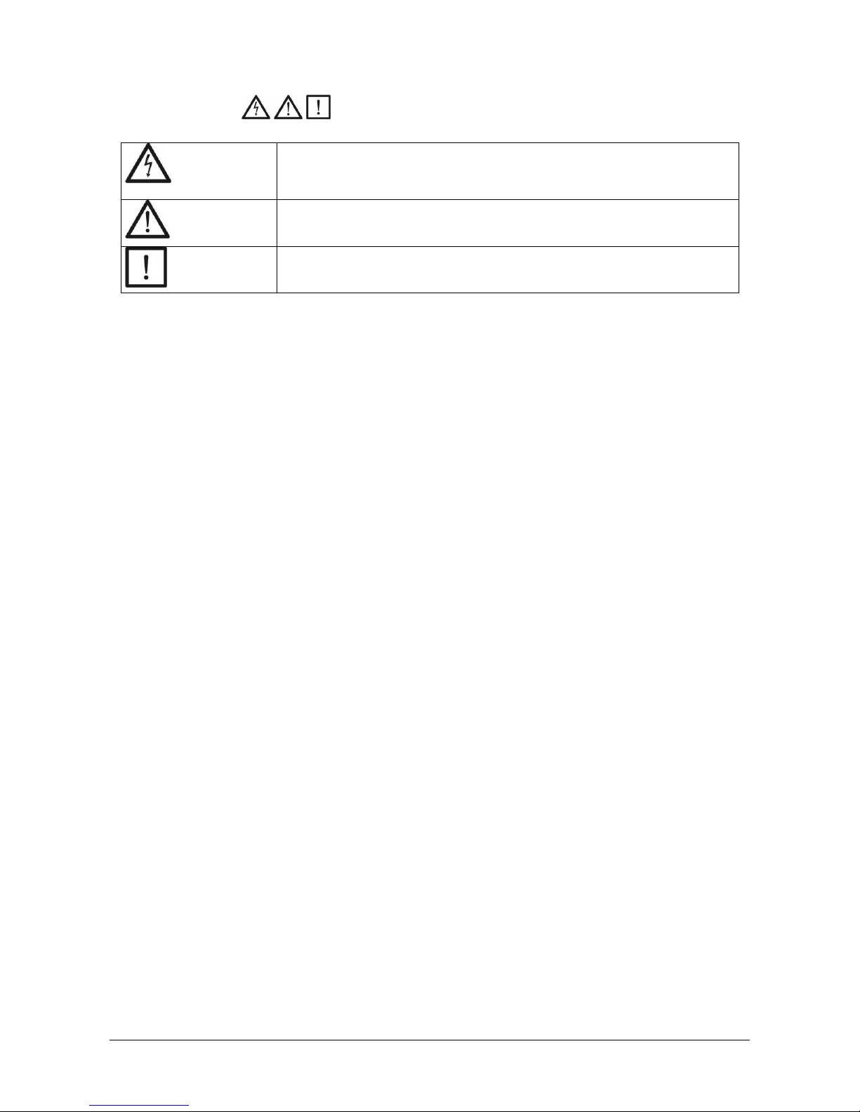
The following symbols shown beside a paragraph represent danger warnings associated to the
failure to comply with the corresponding instructions.
DANGER!
DANGER!DANGER!
DANGER!
Risk of
Risk ofRisk of
Risk of
electrocution.
electrocution.electrocution.
electrocution.
Not observing this precaution involves a risk of electrocution.
DANGER!
DANGER!DANGER!
DANGER!
Warns that not observing the precaution involves a risk of damage to people
and/or materials.
WARNING
WARNINGWARNING
WARNING
Warns that not observing the precaution involves a risk of damage to the pump
or the installation.
TABLE OF CONTENTS
TABLE OF CONTENTSTABLE OF CONTENTS
TABLE OF CONTENTS
1) GENERAL INFORMATION....................................................................................................................................3
2) TECHNICAL SPECIFICATIONS..............................................................................................................................3
2.1) Models. .....................................................................................................................................................3
2.2) Dimensions. ..............................................................................................................................................3
2.3) Features. ...................................................................................................................................................3
3) INSTALLATION. .................................................................................................................................................4
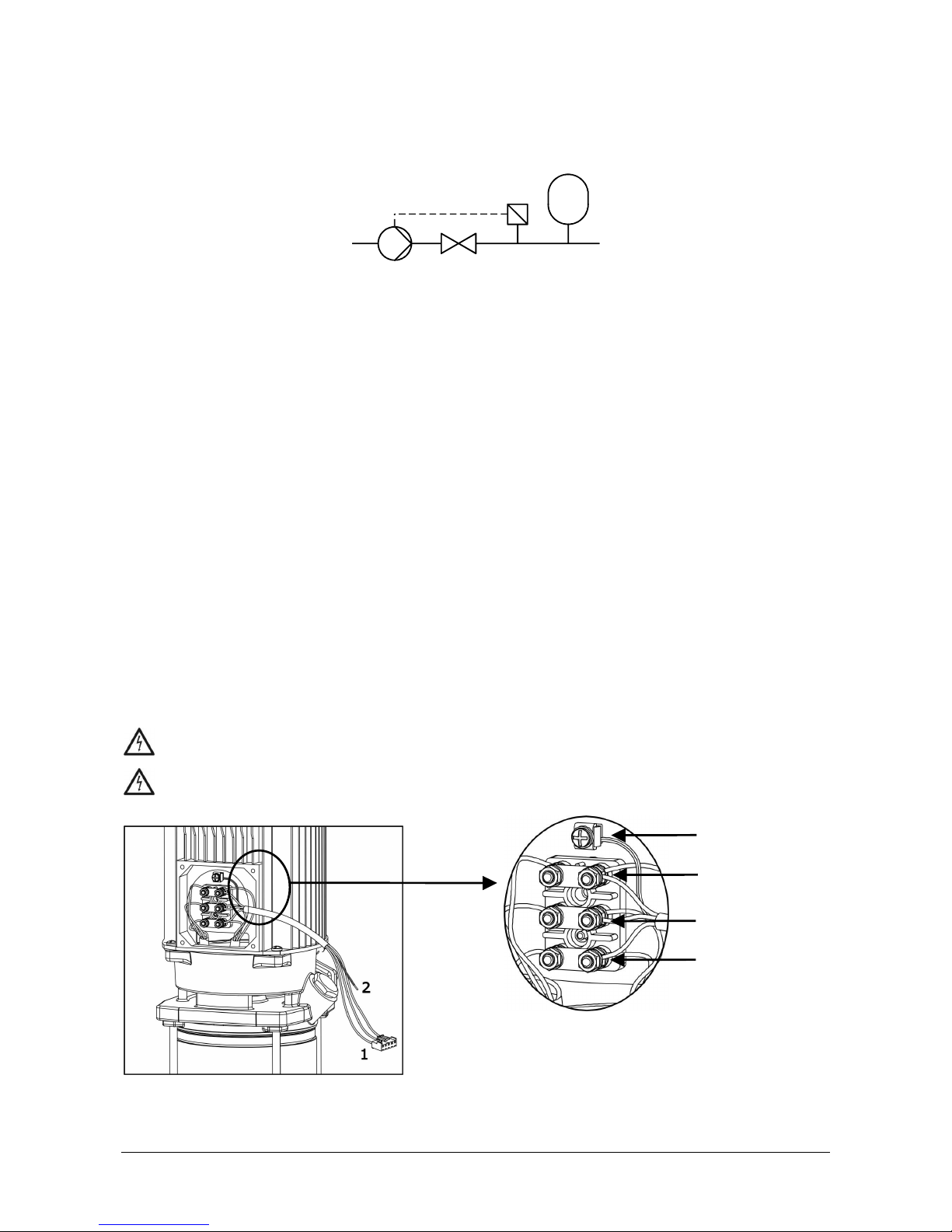
3.1) Hydraulic installation.................................................................................................................................4
3.2) Electrical connection to the motor. .............................................................................................................4
3.3) Installation on the pump............................................................................................................................5
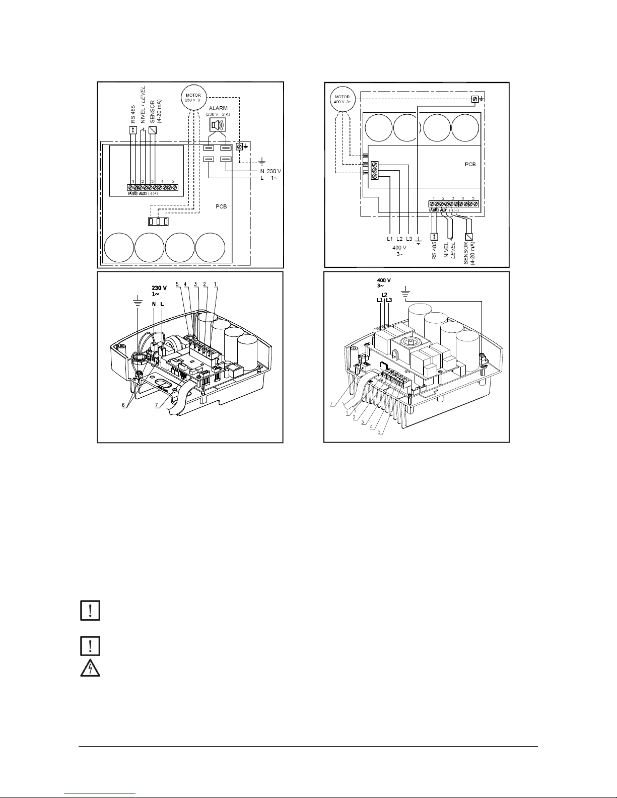
3.4) Power supply connection. ..........................................................................................................................7
3.5) Signals wires connection. ..........................................................................................................................8
4) OPERATING MODES. .........................................................................................................................................9
5) SETUP. .............................................................................................................................................................9
5.1) Definitions.................................................................................................................................................9
5.2) Browsing. ..................................................................................................................................................9
5.3) Description of the menus. ........................................................................................................................10
6) PROTECTION AND ERRORS. .............................................................................................................................15
ELECTRONIC CIRCUIT FAILURE..........................................................................................................................16
7) MULTIPLE OPERATION.....................................................................................................................................16
7.1) Booster set with "On-Off" auxiliary pumps ...............................................................................................16
7.2) Booster set with inverter regulated auxiliary pumps. ................................................................................17
8) MAIN COMPONENTS .......................................................................................................................................20
9) EVIDENCE OF CONFORMITY .............................................................................................................................20
9.1) LOW VOLTAGE..........................................................................................................................................20
9.2) ELECTROMAGNETIC COMPATIBILITY. .........................................................................................................20
9.3) OTHER INSTALLATIONS.............................................................................................................................20
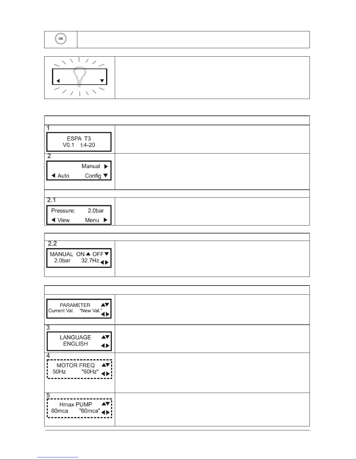
10) MENU DIAGRAM............................................................................................................................................21

- 3 -
1) GENERAL INFORMATION.
1) GENERAL INFORMATION.1) GENERAL INFORMATION.
1) GENERAL INFORMATION.
The Speedrive inverters have been designed to adjust the speed of three
threethree
three-
--
-phase motors
phase motorsphase motors
phase motors used with water pumps.
The inverter receives a signal from the pressure transducer that is proportional to the installation's pressure. This signal
is processed and it regulates the speed of the motor to keep the pressure constant, even though the consumption of
water varies.
It can be used with 50Hz or 60Hz motors. Selecting the output frequency with the menu option.
The units have a constant pressure control system. The PI system used provides two numerical constants that are
processed by the unit to achieve a stable regulation.
This type of regulation can greatly reduce the consumption of energy when compared to unregulated systems,
since the consumption of electricity will be proportional to the consumption of water. Another of the advantages
of regulated units is the decrease in voltage surges, softening current peaks and, therefore, increasing the
working life of the pump.
WARNING: Correct compliance with the installation and operating instructions and the electrical
connection diagrams will guarantee the correct operation of the unit.
DANGER: The failure to follow the instructions in this Manual can lead to motor overloads,
diminishment in technical characteristics, reduction of the unit's working life and all types of
subsequent results, for which we decline any responsibility.
2) TECHNICAL SPECIFICATIONS.
2) TECHNICAL SPECIFICATIONS.2) TECHNICAL SPECIFICATIONS.
2) TECHNICAL SPECIFICATIONS.
2.1) Models.
2.1) Models.2.1) Models.
2.1) Models.
INPUT
INPUTINPUT
INPUT
OUTPUT
OUTPUTOUTPUT
OUTPUT
Dimensions
DimensionsDimensions
Dimensions
Weight
WeightWeight
Weight
Model
ModelModel
Model
Speedrive
SpeedriveSpeedrive
Speedrive
Power
PowerPower
Power
supply
supplysupply
supply
voltage
voltagevoltage
voltage
Max.
Max.Max.
Max.
rated
ratedrated
rated
current
currentcurrent
current
Recommended
RecommendedRecommended
Recommended
line
lineline
line
protection
protectionprotection
protection
Max.
Max.Max.
Max.
motor
motormotor
motor
current
currentcurrent
current
Motor
MotorMotor
Motor
voltage
voltagevoltage
voltage
A
AA
A
B
BB
B
[V]
[V][V]
[V]
[A]
[A][A]
[A]
[A]
[A][A]
[A]
[A]
[A][A]
[A]
[V]
[V][V]
[V]
[mm]
[mm][mm]
[mm]
[mm]
[mm][mm]
[mm]
[kg]
[kg][kg]
[kg]
M2
M2M2
M2 1~ 230V AC
±10% 13.5 20 7 3~ 230V
AC 128 71 2.2
T2
T2T2
T2
7 10 6 2.4
T3
T3T3
T3
3~ 400V AC
±10% 11 15 9
3~ 400V
AC 142 85 2.5
2.2) Dimensions.
2.2) Dimensions.2.2) Dimensions.
2.2) Dimensions.
2.3) Features.
2.3) Features.2.3) Features.
2.3) Features.
• Degree of protection: IP55.
• Maximum working ambient temperature: 40 ºC.
• Inputs: 1 analogue 4-20mA, with 24V DC power supply. 1 digital input for the level switch.
• Outputs: Only M..., 1 potential-free contact, maximum current 2A at 250V AC.
• Communications: RS 485 serial port.

- 4 -
3) INSTALLATION.
3) INSTALLATION.3) INSTALLATION.
3) INSTALLATION.
3.1) Hyd
3.1) Hyd3.1) Hyd
3.1) Hydraulic installation.
raulic installation.raulic installation.
raulic installation.
3.1.1) Installation layout.
1
2
3
4
1. Pump with Speedrive.
2. Non-return valve.
Not required others non-return valves in the delivery pipe.
3. Pressure transducer. The 4-20 mA, 10 bar type,
EMC according EN 61000-6-2.
4. Accumulator.
Its sole function is to compensate minor water losses in the installation, preventing
continuous pump start-ups and stops. The accumulator's volume must be at least 10% of the
nominal flow of the pump(s) installed, calculated in litres per minute. (For ex.: Multi35 5,
QMAX=100 [l/min]x0.1=10 accumulator
≥
10l) The preload pressure must be 1 bar below to
the rated pressure.
3.1.2) Hydraulic connections.
See the pump manual.
For facilities in negative suction, it is required that the pipes are primed completely.
3.2) Elect
3.2) Elect3.2) Elect
3.2) Electrical connection to the motor.
rical connection to the motor.rical connection to the motor.
rical connection to the motor.
3.2.1) Speedrive with single
3.2.1) Speedrive with single3.2.1) Speedrive with single
3.2.1) Speedrive with single-
--
-phase input (Figure 1):
phase input (Figure 1):phase input (Figure 1):
phase input (Figure 1):
The motor must be connected to a 230 V power supply source.
The cable (1) supplied with the inverter must be connected to the motor.
If you wish to activate the 60Hz motor output, select the corresponding parameter in the menu.
Make sure that electrical consumption shown on the motor's data plate does not exceed that supplied by the
inverter.
DANGER.
Risk of electrocution
. Always connect the supplied grounding cable (2) between the motor
and inverter set.
DANGER.
Risk of electrocution
. Never open the Speedrive cover before disconnecting the power
supply during at least 5 minutes
least 5 minutesleast 5 minutes
least 5 minutes.
Figure 1
Figure 1Figure 1
Figure 1
Blue
Brown
Black
Yellow/Green

- 5 -
3.2.2) Speedrive with three
3.2.2) Speedrive with three3.2.2) Speedrive with three
3.2.2) Speedrive with three-
--
-phase input (Figure 2):
phase input (Figure 2):phase input (Figure 2):
phase input (Figure 2):
The motor must be connected to a 400 V power supply source.
The cable (1) supplied with the frequency inverter must be connected to the motor.
If you wish to activate the 60Hz motor output, select the corresponding parameter in the menu.
Make sure that electrical consumption shown on the motor's data plate does not exceed that supplied by the
inverter.
DANGER.
Risk of electrocution.
Always connect the supplied grounding cable (2) between the motor
and inverter set.
DANGER.
Risk of electrocution.
Never open the Speedrive cover before disconnecting the power
supply during at least 5 minutes
least 5 minutesleast 5 minutes
least 5 minutes.
Figure 2
Figure 2Figure 2
Figure 2
3.3) Installation on the pump.
3.3) Installation on the pump.3.3) Installation on the pump.
3.3) Installation on the pump.
The Speedrive is installed on the motor with a special supplied adapter.
The inverter is cooled with the use of the motor's cooling elements.
The unit has been designed for vertical and horizontal installation.
3.3.1) Motor adapter (Figure 3):
3.3.1) Motor adapter (Figure 3):3.3.1) Motor adapter (Figure 3):
3.3.1) Motor adapter (Figure 3):
Replace the connections box with the supplied motor adapter. Use the same screws. Torque 1~1.2 Nm.
Figure 3
Figure 3Figure 3
Figure 3
Azul
Marrón
Negro
Blue
Brown
Black
Yellow/Green

- 6 -
3.3.2) Speedriv
3.3.2) Speedriv3.3.2) Speedriv
3.3.2) Speedrive.
e.e.
e.
Installation of the Speedrive on the adapter. Use the screws (1) supplied.
Torque: 3 Nm.
Single
SingleSingle
Single-
--
-Phase Version
Phase VersionPhase Version
Phase Version
Three
ThreeThree
Three-
--
-Phase Version
Phase VersionPhase Version
Phase Version
Prepare the motor wires with ferrites:
connect the grounding wire (2)
Connect the motor wires to the provided socket (3)
Single
SingleSingle
Single-
--
-Phase Version
Phase VersionPhase Version
Phase Version
Three
ThreeThree
Three-
--
-Phase Version
Phase VersionPhase Version
Phase Version
Figure 4
Figure 4Figure 4
Figure 4
Figure 5
Figure 5Figure 5
Figure 5
1
1
3
2
2
3
4

- 7 -
3.4) Power supply connection.
3.4) Power supply connection.3.4) Power supply connection.
3.4) Power supply connection.
DANGER. Risk of electrocution.
Connection and grounding are compulsory.
All electrical connections will be in accordance with the IEC-60364 Regulations (electrical installation
in buildings) or the regulations in force in the destination country and local regulations.
The power supply line of equipment must be adequately protected. These protection elements will
prevent damage to persons during an electrical leakage. An exclusive power supply line is
recommended.
The system protection will be based on an earth leakage switch (I∆n = 30 mA).
The recommended earth leakage switch is "class A"
"class A""class A"
"class A" for pulsed and continuous currents, marked with the
following symbols:
The earth leakage value will depend on the number of units connected to the line and their power.
Motor size
Motor sizeMotor size
Motor size
Leakage current
Leakage currentLeakage current
Leakage current
0.75 to 3 kW < 3.5 mA
4 to 5.5 kW < 5 mA
The electrical installation should have a multiple separation system with contact openings ≥3 mm.
Single
SingleSingle
Single-
--
-phase frequency inverters.
phase frequency inverters.phase frequency inverters.
phase frequency inverters.
These units are supplied with a H07 RN-F power supply cable, 2m length and a connection plug. The power supply
input must be single-phase, at 230 V, 50 or 60 Hz.
See Figure 6
Figure 6Figure 6
Figure 6 for reference.
Voltage variations allowed ±10
Three
ThreeThree
Three-
--
-phase frequency inverters.
phase frequency inverters.phase frequency inverters.
phase frequency inverters.
These units have a three-phase power supply input, at 400 V, 50 or 60 Hz. The cabling procedures must be
undertaken by a professional installation entity.
Connection socket according figure 5
figure 5figure 5
figure 5 (4)
(4)(4)
(4). Connections, in accordance with Figure 7
Figure 7Figure 7
Figure 7.
Voltage variations allowed ±10%.
Preparing the power supply wires:

- 8 -
3.5) Signals wires connection.
3.5) Signals wires connection.3.5) Signals wires connection.
3.5) Signals wires connection.
Single
SingleSingle
Single-
--
-phase version
phase versionphase version
phase version
Three
ThreeThree
Three-
--
-Phase Version
Phase VersionPhase Version
Phase Version
Figure 6
Figure 6Figure 6
Figure 6
Figure 7
Figure 7Figure 7
Figure 7
1.- RS 485 communications output to connect various inverters. Up to 4 units.
2.- Auxiliary input for an external level switch or a potential-free contact to activate or stop the circuit.
Note: This input is supplied from the factory with an electric cable bridge.
3.- Input of the 4-20mA pressure transducer.
4.- Potential-free auxiliary input. Not used.
5.- Auxiliary transducer input. Not used.
6.- Only in single-phase versions. 230 V potential output, 2A maximum, external display or acoustic
operation for alarm signals.
7.- Micro-switches used to configure the inverter's operation.
WARNING: All external cabling connections must use terminal tips on the ends of each cable. External
cables must comply with the corresponding electrical safety and insulation regulations. Installation
should be made by qualified service personnel.
Avoid any cable pieces from falling inside the circuit, which could lead to its destruction.
DANGER. Risk of electrocution.
If the unit has to be uncovered due to any circumstance, first disconnect the power supply and wait 5
minutes before starting work with the circuit. The circuit's capacitors store energy. There is enough
energy inside the circuit to cause a strong electric discharge, even when the unit is not powered.

- 9 -
If necessary, reconnect the display cable to the motherboard.
Give special attention to positioning.
Single
SingleSingle
Single-
--
-Phase Version
Phase VersionPhase Version
Phase Version
Three
ThreeThree
Three-
--
-Phase Version
Phase VersionPhase Version
Phase Version
4) OPERATING MODES.
4) OPERATING MODES.4) OPERATING MODES.
4) OPERATING MODES.
Automatic mode.
Automatic mode.Automatic mode.
Automatic mode.
This is the common operating mode.
The inverter controls the motor's rotation speed to maintain a constant pressure in the installation (set pressure).
Manual mode.
Manual mode.Manual mode.
Manual mode.
Allows the pump start-up or stop manually at an adjustable frequency.
5) SETUP.
5) SETUP.5) SETUP.
5) SETUP.
Espa ESD pumps and Espa pressure booster sets are pre
Espa ESD pumps and Espa pressure booster sets are preEspa ESD pumps and Espa pressure booster sets are pre
Espa ESD pumps and Espa pressure booster sets are pre-
--
-configured in origin with an optimum pressure set
configured in origin with an optimum pressure setconfigured in origin with an optimum pressure set
configured in origin with an optimum pressure set
point for equipped pumps.
point for equipped pumps.point for equipped pumps.
point for equipped pumps. Do not need any further adjustment.
Do not need any further adjustment.Do not need any further adjustment.
Do not need any further adjustment.
Speedrive module purchased separately, is necessary its configuration, according to the following paragraphs.
5.1) Definitions.
5.1) Definitions.5.1) Definitions.
5.1) Definitions.
Set pressure:
Set pressure:Set pressure:
Set pressure: is the pressure that the unit will maintain in the installation.
Differentia
DifferentiaDifferentia
Differential pressure:
l pressure:l pressure:
l pressure: is the differential pressure required for the unit to activate again.
Stop frequency:
Stop frequency:Stop frequency:
Stop frequency: frequency at which the inverter stops the pump.
Stop delay:
Stop delay:Stop delay:
Stop delay: timer used by the unit before it stops.
Auxiliary
AuxiliaryAuxiliary
Auxiliary
“on
“on“on
“on-
--
-off” pump:
off” pump:off” pump:
off” pump: auxiliary pump that is not equipped with Speedrive.
Auxiliary
AuxiliaryAuxiliary
Auxiliary
regulated pump:
regulated pump:regulated pump:
regulated pump: auxiliary pump that is equipped with a Speedrive.
5.2) Browsing.
5.2) Browsing.5.2) Browsing.
5.2) Browsing.
Screen displaying
the menus
Browsing keys
Flashing = pump waiting
Fixed = pump operating
Failure
See description on screen
Power supply plug-in
Browsing the menus.
Variation of the flashing parameter.
Browsing a submenu.

- 10 -
Accepting changes.
Return to the general screen from display of parameters.
Pressure: 2.0bar
MenuView
Backlight
BacklightBacklight
Backlight
The screen is backlit display for better reading.
To save power, the backlight turns off in 60 seconds without pressing any keys.
To activate the backlight, press OK
OKOK
OK.
Without backlight does not work any other key.
5.3)
5.3)5.3)
5.3) Description of the menus.
Description of the menus.Description of the menus.
Description of the menus.
START SCREENS
START SCREENSSTART SCREENS
START SCREENS
Introduction screen
Introduction screenIntroduction screen
Introduction screen
Displayed during a few seconds when connecting the equipment.
Indicates: model, software version and pressure sensor configuration.
Start screen
Start screenStart screen
Start screen
The pump is not activated.
To start the pump manually, press ►(Man)
For automatic operation, press ◄(Auto)
To configure parameters, press ▼(Config)
MAIN SCREEN
MAIN SCREENMAIN SCREEN
MAIN SCREEN
It shows the system pressure. The pump will run automatically, as needed.
To display parameters, press ◄(View)
To return to the start screen, press ►(Menu)
MANUAL OPERATION
MANUAL OPERATIONMANUAL OPERATION
MANUAL OPERATION
It shows the system pressure and Speedrive output frequency.
Press ▲ON, to activate the pump. Start-up is always performed at 15Hz.
Press▼OFF, to stop the pump.
Press◄or ►, to adjust the frequency.
Press O
OO
OK
KK
K to exit the screen.
CONFIGURATION
CONFIGURATIONCONFIGURATION
CONFIGURATION
Screen descriptions:
- Top : parameter being configured.
- Lower left : current value of the parameter.
- Lower right, "flashing": new value being configured. Press OK
OKOK
OK to confirm.
LANGUAGE
LANGUAGELANGUAGE
LANGUAGE
Select the desired language.
MOTOR FREQUENCY
MOTOR FREQUENCYMOTOR FREQUENCY
MOTOR FREQUENCY
Configuration of the nominal frequency of the motor, 50Hz or 60Hz.
Check the motor's nameplate.
Note: This screen only appears in the initial preset or retrieving the factory
settings.
MAXIMUM PUMP HEIGHT
MAXIMUM PUMP HEIGHTMAXIMUM PUMP HEIGHT
MAXIMUM PUMP HEIGHT
Setting the maximum pressure the pump can provide.
Check the pump’s nameplate.
Note: This screen only appears in the initial preset or retrieving the factory settings

- 11 -
MAXIMUM MOTOR CURRENT
MAXIMUM MOTOR CURRENTMAXIMUM MOTOR CURRENT
MAXIMUM MOTOR CURRENT
Maximum operating current of the motor.
Adjust in accordance with the motor's data plate, plus 10%.
Note: This screen only appears in the initial preset or retrieving the factory settings
NOMINAL PRESSURE
NOMINAL PRESSURENOMINAL PRESSURE
NOMINAL PRESSURE
Configuration of the work pressure of the unit.
CONFIGURATION OF THE STOP FREQUENCY
CONFIGURATION OF THE STOP FREQUENCYCONFIGURATION OF THE STOP FREQUENCY
CONFIGURATION OF THE STOP FREQUENCY
CALCULATED STOP FREQUENCY
CALCULATED STOP FREQUENCYCALCULATED STOP FREQUENCY
CALCULATED STOP FREQUENCY
The stop frequency is calculated automatically.
Will be recalculated every time that is changed the nominal pressure.
To set a value in the manual mode, press◄(Man)
STOP FREQUENCY MANUALLY
STOP FREQUENCY MANUALLYSTOP FREQUENCY MANUALLY
STOP FREQUENCY MANUALLY
Enter the desired stop frequency.
Note: This value should only be entered by experts.
ADDITIONAL PARAMETERS SETTING
ADDITIONAL PARAMETERS SETTINGADDITIONAL PARAMETERS SETTING
ADDITIONAL PARAMETERS SETTING
FINE ADJUSTMENTS
FINE ADJUSTMENTSFINE ADJUSTMENTS
FINE ADJUSTMENTS
To set additional parameters, press ▼(Config)
To complete the setup, press ◄(Exit)
DIFFERENTIAL PRESSURE
DIFFERENTIAL PRESSUREDIFFERENTIAL PRESSURE
DIFFERENTIAL PRESSURE
Configuration of the difference between the set and start-up pressure.
For ex. : 3 bars set – 0.5 bars differential = 2.5 bars start-up
STOP DELAY
STOP DELAYSTOP DELAY
STOP DELAY
Timing of the unit before a stop. This timing process is associated to the stop
frequency.
REVESE ROTATION
REVESE ROTATIONREVESE ROTATION
REVESE ROTATION
To check the motor rotation direction, press ►(Check)
To change rotation direction, press ◄(Change)
Starting the motor, to 25Hz, for CHECK TURN DIRECTION
Press ▲ON, to activate the pump.
Press▼OFF, to stop the pump.
Press OK
OKOK
OK to exit the screen.
Confirm INVERT TURN.
Change to "YES" to reverse the turn direction
AUXILIARY PUMPS
AUXILIARY PUMPSAUXILIARY PUMPS
AUXILIARY PUMPS
For adjust auxiliary pumps parameters, press ►(Adjust)
If there are no regulated pumps, press ▼to advance to screen 11.

- 12 -
CONFIGURATION SUBMENU FOR AUXILIARY
CONFIGURATION SUBMENU FOR AUXILIARYCONFIGURATION SUBMENU FOR AUXILIARY
CONFIGURATION SUBMENU FOR AUXILIARY
PUMPS
PUMPSPUMPS
PUMPS
MAXIMUM CURRENT OF THE AUXILIARY PUMP (ELV only)
MAXIMUM CURRENT OF THE AUXILIARY PUMP (ELV only)MAXIMUM CURRENT OF THE AUXILIARY PUMP (ELV only)
MAXIMUM CURRENT OF THE AUXILIARY PUMP (ELV only)
Maximum motor current of the auxiliary pumps equipped with "ELV" box.
All motors have the same power rating.
Adjust in accordance with the motor's data plate, plus 10%.
Adjust in accordance with the motor's data plate, plus 10%.Adjust in accordance with the motor's data plate, plus 10%.
Adjust in accordance with the motor's data plate, plus 10%.
For auxiliary pumps equipped with "SPEEDRIVE" box this parameter must be
regulated individually, for each equipment. The value of this screen is ignored.
FREQUENCY "ON" FOR AUXILIARY PUMPS
FREQUENCY "ON" FOR AUXILIARY PUMPSFREQUENCY "ON" FOR AUXILIARY PUMPS
FREQUENCY "ON" FOR AUXILIARY PUMPS
Auxiliary pump activation frequency.
Maximum frequency achieved by the main pump. At this frequency, the 1
st
auxiliary
pump is activated, lowering the main pump frequency until it balances the set
pressure. If the main pump reaches this frequency again, the 2
nd
auxiliary pump will be
activated, and so forth.
The number of auxiliary pumps does not have to be determined, since the circuit
communications system detects its number.
DELAY ON
DELAY ONDELAY ON
DELAY ON
Delay time between the activation of auxiliary pumps.
Avoid continuous start-ups of reserve pumps due to fluctuations in the
installation.
HYSTERESIS OFF
HYSTERESIS OFFHYSTERESIS OFF
HYSTERESIS OFF
Difference between the stop frequency of the main pump and each auxiliary pump.
DELAY HYSTERESIS OF
DELAY HYSTERESIS OFDELAY HYSTERESIS OF
DELAY HYSTERESIS OFF
FF
F
Delay time in the stop sequence of auxiliary pumps.
PARAMETER RESET
PARAMETER RESETPARAMETER RESET
PARAMETER RESET
FACTORY PARAMETER
FACTORY PARAMETERFACTORY PARAMETER
FACTORY PARAMETER
To reset all changes of parameters and return to default settings, click OK
OKOK
OK.
Confirm the change to default parameters.
Select "Yes" and click OK
OKOK
OK to return to the default settings.
CONFIGURATION OF ADVANCED PARAMETERS AND METER RESET
CONFIGURATION OF ADVANCED PARAMETERS AND METER RESETCONFIGURATION OF ADVANCED PARAMETERS AND METER RESET
CONFIGURATION OF ADVANCED PARAMETERS AND METER RESET
ADVANCED PARAMETERS
ADVANCED PARAMETERSADVANCED PARAMETERS
ADVANCED PARAMETERS
To modify the advanced parameters or reset the meters, press ▼
To complete the setup, click OK
OKOK
OK.
ATTENTION. These parameters can only be configured by expert staff.
PASSWORD
PASSWORDPASSWORD
PASSWORD
There are 2 passwords available, depending on the action:
◄◄◄ + OK
+ OK+ OK
+ OK: to reset all meters.
►►► + OK
+ OK+ OK
+ OK: to adjust the unit's regulation and operation.

- 13 -
SUBMENU USED TO RESET METERS (password
SUBMENU USED TO RESET METERS (passwordSUBMENU USED TO RESET METERS (password
SUBMENU USED TO RESET METERS (password ◄◄◄)
))
)
RESET METER
RESET METERRESET METER
RESET METER
Select "Yes" and click OK
OKOK
OK to reset all meters.
Confirm RESET METER.
Select "Yes" and click OK
OKOK
OK to confirm reset all meters.
RESET ALARMS
RESET ALARMSRESET ALARMS
RESET ALARMS
Select "Yes" and click OK
OKOK
OK to reset all alarms.
Confirm RESET ALARMS.
Select "Yes" and click OK
OKOK
OK to confirm reset all alarms.
SUBMENU FOR THE CONFIGURATION OF ADVANCED PARAMETERS (password
SUBMENU FOR THE CONFIGURATION OF ADVANCED PARAMETERS (passwordSUBMENU FOR THE CONFIGURATION OF ADVANCED PARAMETERS (password
SUBMENU FOR THE CONFIGURATION OF ADVANCED PARAMETERS (password ►►►)
))
)
WORK PROPORTIONAL CONSTANT
WORK PROPORTIONAL CONSTANTWORK PROPORTIONAL CONSTANT
WORK PROPORTIONAL CONSTANT
Allows the variation of the unit's proportional constant after start-up.
WORK INTEGRAL CONSTANT
WORK INTEGRAL CONSTANTWORK INTEGRAL CONSTANT
WORK INTEGRAL CONSTANT
Allows the variation of the unit's integral constant after start-up.
START PROPORTIONAL CONSTANT
START PROPORTIONAL CONSTANTSTART PROPORTIONAL CONSTANT
START PROPORTIONAL CONSTANT
Allows the variation of the unit's proportional constant upon start-up.
STAR INTEGRAL CONSTANT
STAR INTEGRAL CONSTANTSTAR INTEGRAL CONSTANT
STAR INTEGRAL CONSTANT
Allows the variation of the unit's integral constant upon start-up.
PWM FREQUENCY (Pulse Width Modulation)
PWM FREQUENCY (Pulse Width Modulation)PWM FREQUENCY (Pulse Width Modulation)
PWM FREQUENCY (Pulse Width Modulation)
Allows the variation of the internal module switching tasks.
A high-pitched sound will be heard from the motor (depending on the type of
motor) when the switching frequency is varied.
DISPLAY OF PARAMETERS
DISPLAY OF PARAMETERSDISPLAY OF PARAMETERS
DISPLAY OF PARAMETERS
DISPLAY OF PARAMETERSDISPLAY OF PARAMETERS
DISPLAY OF PARAMETERS
Press OK
OKOK
OK to confirm.
Parameters can only be displayed, not modified.
To display the alarms, press ◄(Alarm)
To return to the main screen, press ►(Auto)
From any screen, tap OK to return to the main
From any screen, tap OK to return to the mainFrom any screen, tap OK to return to the main
From any screen, tap OK to return to the main screen 2.1
screen 2.1screen 2.1
screen 2.1
NOMINAL PRESSURE
NOMINAL PRESSURENOMINAL PRESSURE
NOMINAL PRESSURE
Work pressure assigned to the unit.

- 14 -
DIFFERENTIAL PRESSURE
DIFFERENTIAL PRESSUREDIFFERENTIAL PRESSURE
DIFFERENTIAL PRESSURE
Difference between the set and start-up pressure.
For ex. : 3 bars set – 0.5 bars differential = 2.5 bars start-up
MAXIMUM MOTOR CURRENT
MAXIMUM MOTOR CURRENTMAXIMUM MOTOR CURRENT
MAXIMUM MOTOR CURRENT
Maximum configured current/ Present current
STOP FREQUENCY
STOP FREQUENCYSTOP FREQUENCY
STOP FREQUENCY
Stop frequency of the inverter / Present output frequency
STOP DELAY
STOP DELAYSTOP DELAY
STOP DELAY
Timing before a stop.
MODULE TEMPERATURE
MODULE TEMPERATUREMODULE TEMPERATURE
MODULE TEMPERATURE
Current temperature of the module or circuit.
DISPLAY OF THE ALARM LOG
DISPLAY OF THE ALARM LOGDISPLAY OF THE ALARM LOG
DISPLAY OF THE ALARM LOG
DISPLAY ALARMS
DISPLAY ALARMSDISPLAY ALARMS
DISPLAY ALARMS
Press OK
OKOK
OK to confirm.
To display the log, press ◄(Hist)
To display the parameters, press ►(Param)
From any screen, tap OK to return to the main screen 2.1
From any screen, tap OK to return to the main screen 2.1From any screen, tap OK to return to the main screen 2.1
From any screen, tap OK to return to the main screen 2.1
OVERCURRENT
OVERCURRENTOVERCURRENT
OVERCURRENT
Number of times an overcurrent is detected.
(see Section 6)
SHORT
SHORTSHORT
SHORT-
--
-CIRCUIT
CIRCUITCIRCUIT
CIRCUIT
Number of times a fault caused by a short-circuit is detected.
(see Section 6)
VOLTAGE
VOLTAGEVOLTAGE
VOLTAGE
Number of times the inverter has stopped due to a voltage fault.
(see Section 6)
MODULE TEMPERATURE
MODULE TEMPERATUREMODULE TEMPERATURE
MODULE TEMPERATURE
Number of times the inverter has stopped due to excess temperature in the
module.
(see Section 6)
LACK OF WATER LEVEL IN TANK
LACK OF WATER LEVEL IN TANKLACK OF WATER LEVEL IN TANK
LACK OF WATER LEVEL IN TANK
Number of times the inverter has stopped by activating the probe level.
(see Section 6)
DISPLAY OF THE OPERATION LOG
DISPLAY OF THE OPERATION LOGDISPLAY OF THE OPERATION LOG
DISPLAY OF THE OPERATION LOG
DISPLAY LOG
DISPLAY LOGDISPLAY LOG
DISPLAY LOG
Press Ok to confirm.
To display the alarms, press ►(Alarm)

- 15 -
From any screen, tap OK to return to the main screen 2.1
From any screen, tap OK to return to the main screen 2.1From any screen, tap OK to return to the main screen 2.1
From any screen, tap OK to return to the main screen 2.1
NUMBER OF START
NUMBER OF STARTNUMBER OF START
NUMBER OF START-
--
-UPS
UPSUPS
UPS
Number of pump start-ups.
OPERATING HOURS
OPERATING HOURSOPERATING HOURS
OPERATING HOURS
Number of hours of operation of the pump.
LINE CONNECTION
LINE CONNECTIONLINE CONNECTION
LINE CONNECTION
Number of hours of connection to the line, even when the pump is stopped.
6) PROTECTION AND ERRORS.
6) PROTECTION AND ERRORS.6) PROTECTION AND ERRORS.
6) PROTECTION AND ERRORS.
OVERCURRENTS
OVERCURRENTSOVERCURRENTS
OVERCURRENTS
The circuit permanently controls the motor’s current consumption. If the current
exceeds the values established in parameter "MAXIMUM MOTOR CURRENT" at any
moment, the system will stop.
The reset is automatic. If the error is not solved 4 new attempts* are performed.
If the error is still present after the fourth attempt, the system will be set to a
permanent fault.
Press OK to reset. The start screen (#2) will appear.
SHORT
SHORTSHORT
SHORT-
--
-CIRCUIT
CIRCUITCIRCUIT
CIRCUIT
The state of connections will be diagnosed upon the motor's start-up.
The system will stop when a short-circuit is detected in the motor.
The reset is automatic. If the error is not solved 4 new attempts* are performed.
If the error is still present after the fourth attempt, the system will be set to a
permanent fault.
MODULE TEMPERATURE
MODULE TEMPERATUREMODULE TEMPERATURE
MODULE TEMPERATURE
The module's (T models) or circuit's (M models) temperature is monitored at all
times.
If the limit values established (not configurable) are exceeded in each circuit, the
system will stop.
The reset is automatic when the normal temperature is reinstated.
LACK OF WATER LEVEL IN TANK
LACK OF WATER LEVEL IN TANKLACK OF WATER LEVEL IN TANK
LACK OF WATER LEVEL IN TANK
If you have installed a float level in the inlet water tank (see apt. 3.5, n º 2), the
water level is below the minimum.
The reset is automatic when the water level recovered.
VOLTAGE
VOLTAGEVOLTAGE
VOLTAGE
The input voltage of the system will be monitored constantly.
The system will stop if the ±10% limits are exceeded.
The reset is automatic when the nominal voltage is reinstated.
PRESSURE TRANSDUCER
PRESSURE TRANSDUCERPRESSURE TRANSDUCER
PRESSURE TRANSDUCER
The pressure transducer connected to the unit is not working properly
The system will stop.
(For booster sets, if other transducers are connected to Speedrive slaves, the
booster will not stop and automatically switch to another transducer)
OVERCURRENT
ERROR
TEMPERATURE
ERROR
VOLTAGE
ERROR
PRESS TRANSD.
ERROR
SHORT-CIRCUIT
ERROR
LACK LEVEL
ERROR

- 16 -
LACK OF WATER / PIPE
LACK OF WATER / PIPELACK OF WATER / PIPE
LACK OF WATER / PIPE BREAKAGE
BREAKAGEBREAKAGE
BREAKAGE
If the unit works more than 60 seconds at 50Hz, but the pressure does not exceed
0.3 bar, is declared "error for lack of water."
the system will be set to a permanent fault.
Press OK to reset.
ELECTRONIC CIRCUIT
ELECTRONIC CIRCUITELECTRONIC CIRCUIT
ELECTRONIC CIRCUIT FAILURE
FAILUREFAILURE
FAILURE
The electronic circuit is breakdown.
The Speedrive stops working. It can only be repaired by official technical service.
MEMORY MODULE FAILURE
MEMORY MODULE FAILUREMEMORY MODULE FAILURE
MEMORY MODULE FAILURE
EEPROM memory module has had a serious malfunction and has stopped working.
The Speedrive enters standby mode, with a reference pressure of 2 bar. It can only
be repaired by official technical service.
DISPLAY CONNECTION ERROR
DISPLAY CONNECTION ERRORDISPLAY CONNECTION ERROR
DISPLAY CONNECTION ERROR
3 LED sequential lighting indicates an error in
connection the display signal cable to the
motherboard.
Reverse connector. Take care to position
*= Illustration of the sequence and times of the 4 attempts, if not none of them succeed:
1’ 5’
15’
60’
ON
OFF
1º
3º
2º
4º
7) MULTIPLE OPERATION.
7) MULTIPLE OPERATION.7) MULTIPLE OPERATION.
7) MULTIPLE OPERATION.
The Speedrive inverter can control more up to 4 pumps, equipped with various Espa solutions, for a multiple
pump booster set control.
a) Booster set with "On-Off" auxiliary pumps , equipped with "ELV" box .
b) Booster set with inverter regulated auxiliary pumps, equipped with "Speedrive" box in slave mode.
Communication is through communication port RS-485.
7.1) Booster set with "On
7.1) Booster set with "On7.1) Booster set with "On
7.1) Booster set with "On-
--
-Off" auxiliary pumps
Off" auxiliary pumpsOff" auxiliary pumps
Off" auxiliary pumps
Sequence of Operation:
- Faced with a demand for water, the pump A starts fast enough to meet the need for installation.
- If the need is beyond the capacity of the pump A, pump B is activated at 100% capacity. The pump A reduce
speed to meet demand (exchange rate set according to menu 10.1)
- If the need exceeds the capacity of the pumps A + B, the pump C is activated. The pump A reduce speed to
meet demand.
- And successively...
The operation mode is alternated. Each activation of the booster set, the order of start pumps is random. This will
equal the operation hours.
Installation and connections.
Installation and connections.Installation and connections.
Installation and connections.
The Speedrive installation and electrical wiring is done as described in this manual.
For installation and connections of the modules "ELV", see its installation manual.
The connection of the pressure transducer must be made solely on the drive Speedrive.
A 2-wire twisted and shielded cable 0.5mm2 section must make the communication between devices.
LACK OF WATER
ERROR
INTERNAL FAILURE
ERROR
EEPROM FILURE
ERROR

- 17 -
Figure 8
Figure 8Figure 8
Figure 8
Adjust the micro
Adjust the microAdjust the micro
Adjust the micro-
--
-switches on the ELV as needed
switches on the ELV as neededswitches on the ELV as needed
switches on the ELV as needed. See section 5 of the ELV manual.
Respect the polarity of the RS-485connection:
1
3
2
1
3
2
1
3
2
1
3
2
A B A B
A
B
A
B
Configuration.
Configuration.Configuration.
Configuration.
Set Speedrive menus as follows:
AUXILIARY PUMP
AUXILIARY PUMPAUXILIARY PUMP
AUXILIARY PUMP
Press ►(Adjust) for the adjustment of the parameters that govern to the
auxiliary pumps.
MAXIMUM CURRENT OF THE AUXILIARY PUMP.
MAXIMUM CURRENT OF THE AUXILIARY PUMP.MAXIMUM CURRENT OF THE AUXILIARY PUMP.
MAXIMUM CURRENT OF THE AUXILIARY PUMP.
Set the maximum motor current of the auxiliary pumps, according to his
motor's data plate plus 10%.
plus 10%.plus 10%.
plus 10%.
All auxiliary pump motors should be of the same power.
CHANGE FREQUENCY
CHANGE FREQUENCYCHANGE FREQUENCY
CHANGE FREQUENCY
Set the maximum frequency of the main pump to be activated the auxiliary
pumps.
The number of auxiliary pumps does not have to be determined, since the
circuit communications system detects the number (maximum 4).
DELAY ON
DELAY ONDELAY ON
DELAY ON
Set the desired delay time before the start of each auxiliary pump.
Programming cascade spreads auxiliary pumps.
Ignore. Press ▼
Ignore. Press ▼
7.2) Booster set with inverter regulated auxiliary pumps.
7.2) Booster set with inverter regulated auxiliary pumps.7.2) Booster set with inverter regulated auxiliary pumps.
7.2) Booster set with inverter regulated auxiliary pumps.
Synchronous sequence of Operation:
- Faced with a demand for water, the pump A starts fast enough to meet the need for installation.

- 18 -
- If the need is beyond the capacity of the pump A, pump B is activated. Both pumps sync speed to meet
demand (exchange rate set according to menu 10.4)
- If the need exceeds the capacity of the pumps A + B, the pump C is activated. Three pumps sync speed to
meet demand.
- And successively...
The operation mode is alternated. For each activation of the booster set, the order of start pumps is random. This
will equal the operation hours.
Installation and connections.
Installation and connections.Installation and connections.
Installation and connections.
The Speedrive installation and electrical wiring is done as described in this manual.
The connection of the pressure transducer must be made solely on the "Master" Speedrive.
A 2-wire twisted and shielded cable 0.5mm2 section must make the communication between devices.
Figure 9
Figure 9Figure 9
Figure 9
Adjust the micro-switches (
figure 6 o figure 7
) as needed:
MASTER/SLAVE
SWITCH 1 SWITCH 2 SWITCH 3 SWITCH 4
MASTER OFF OFF OFF OFF
SLAVE 1 OFF OFF OFF ON
SLAVE 2 OFF OFF ON OFF
SLAVE 3 OFF OFF ON ON
Respect the polarity of the RS-485connection:
1
3
2
1
3
2
1
3
2
1
3
2
A B A B
A
B
A
B
Configuration.
Configuration.Configuration.
Configuration.
Set master Speedrive menus as follows:
AUXILIAR
AUXILIARAUXILIAR
AUXILIARY PUMP
Y PUMPY PUMP
Y PUMP
Press ►(Adjust) for the adjustment of the parameters that govern to the
auxiliary pumps.
Ignore. Press ▼

- 19 -
CHANGE FREQUENCY
CHANGE FREQUENCYCHANGE FREQUENCY
CHANGE FREQUENCY
Set the maximum frequency of the main pump to be activated the auxiliary
pumps.
The number of auxiliary pumps does not have to be determined, since the
circuit communications system detects the number (maximum of 4).
DELAY ON
DELAY ONDELAY ON
DELAY ON
Set the desired delay time before the start of each auxiliary pump.
Programming cascade spreads auxiliary pumps.
HYSTERESIS OFF
HYSTERESIS OFFHYSTERESIS OFF
HYSTERESIS OFF
Set the desired difference between the stop frequency of the main pump and
each auxiliary pump.
Programming cascade spreads auxiliary pumps.
DELAY OFF.
Set the desired delay time in the stop sequence of auxiliary pumps.
Programming cascade spreads auxiliary pumps.
Set slave Speedrive menu as follows:
MOTOR FREQUENCY
MOTOR FREQUENCYMOTOR FREQUENCY
MOTOR FREQUENCY
Configuration of the nominal frequency of the motor, 50Hz or 60Hz.
Check the motor's nameplate.
Note: This screen only appears in the initial preset or retrieving the factory
settings.
MAXIMUM MOTOR
MAXIMUM MOTORMAXIMUM MOTOR
MAXIMUM MOTOR CURRENT
CURRENTCURRENT
CURRENT
Maximum operating current of the motor.
Adjust in accordance with the motor's data plate, plus 10%.
Note: This screen only appears in the initial preset or retrieving the factory
settings
Transducer failure.
Transducer failure.Transducer failure.
Transducer failure.
In a booster unit equipped with multiple transducers, if the main transducer fails, it automatically switches to a
secondary transducer.
In this case, displays the following error:
MAIN TRANSDUCER ERROR
MAIN TRANSDUCER ERRORMAIN TRANSDUCER ERROR
MAIN TRANSDUCER ERROR
It appears an asterisk in the pressure display = it is reading the pressure of an
auxiliary transducer.

- 20 -
8) MAIN COMPONENTS
8) MAIN COMPONENTS8) MAIN COMPONENTS
8) MAIN COMPONENTS
1
2
3
4
5
6
1 Motor adapter with connections box 85x85
2 Motor adapter with connections box 70x70
3 Speedrive box with electronic power circuit
4 Cable with plug
(only
M... versions)
5 Electronic control circuit
6 Speedrive cover
9) EVIDENCE OF CONFORMITY
9) EVIDENCE OF CONFORMITY9) EVIDENCE OF CONFORMITY
9) EVIDENCE OF CONFORMITY
9.1) LOW VOLTAGE.
9.1) LOW VOLTAGE.9.1) LOW VOLTAGE.
9.1) LOW VOLTAGE.
Speedrive is in compliance with directive 2006/95/CE (low voltage) and with harmonized standards EN 60730-1
and EN 60730-2-6
9.2) ELECTROMAGNETIC COMPATIBILITY.
9.2) ELECTROMAGNETIC COMPATIBILITY.9.2) ELECTROMAGNETIC COMPATIBILITY.
9.2) ELECTROMAGNETIC COMPATIBILITY.
Speedrive M1 and M2 are in compliance with directive 2004/108/CE (electromagnetic compatibility), for
industrial environment.
For residential environment, it will require the installation of a lead currents filter to prevent interference in the
mains. The Espa filter code 169777 is recommended.
Speedrive T1, T2 and T3 are in compliance with directive 2004/108/CE (electromagnetic compatibility) for
industrial environment.
Harmonized standards: EN 61000-6-2 and EN 61000-6-4.
9.3) OTHER INSTALLATIONS.
9.3) OTHER INSTALLATIONS.9.3) OTHER INSTALLATIONS.
9.3) OTHER INSTALLATIONS.
Speedrive module has been designed, and is certified, for united installation to the pump electric motor. Any
other configuration or installation can be subject to additional certifications. ESPA 2025 SL disclaims all liability
for uses not covered in this manual.
Pere Tubert
Technical manager
ESPA 2025, S.L.
Table of contents
Other Espa DC Drive manuals