SECTION 4 - INSTALLATION
WARNING: BEFORE PROCEEDING WITH INSTALLATION, ENSURE THAT THE
CONVEYOR BELT DRIVE AND ALL ASSOCIATED EQUIPMENT IS
FULLY ISOLATED AND LOCKED OUT.
CONTACT WITH A MOVING CONVEYOR BELT OR ITS COMPONENTS
CAN RESULT IN SERIOUS INJURY OR DEATH.
4.1 Installation Procedure
1. If the steel skirt plates are greater than dimension A (Sect 3.4) from the belt
surface, it may be necessary to extend the plates closer to the belt. A 150x10
flat bar welded to the outside of the chute or skirt side walls is an easy way to
achieve this, as long as sufficient freeboard is available outside the skirt line.
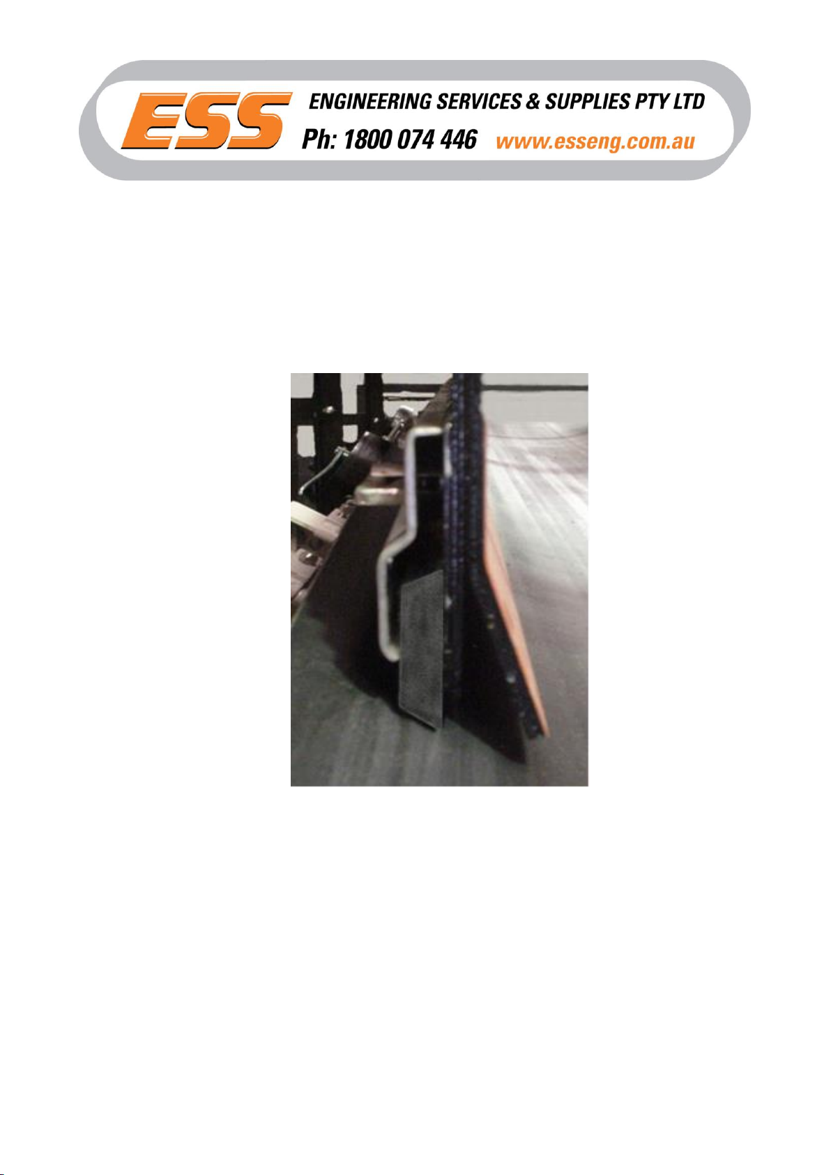
2. Take an ESS 2000 Back Plate section and position it such that the bottom edge
is uniformly dimension A (Sect 3.4) from the belt, and one end is at the required
start point of the skirt seal (preferably toward the tail end of the conveyor). The
bottom edge of the ESS 2000 must not protrude below the bottom edge of the
skirt plate or chute wall –see step 1 above.
Weld the backplate to the skirt / chute wall, using a 3mm x 25 long fillet weld at
the top above each captive wedge, and plug weld in each lower slot. Use an
appropriate welding blanket to protect the belt surface.
3. Repeat step 2 for the full skirt length, simply butting consecutive Backing Plates
against each other, maintaining dimension A from the belt. For skirt lengths that
are multiples of 600mm, and the final or closing length required is 600mm,
simply cut the backing plate in half (2 x 600mm sections), and fit the half length
of Backplate with one full Clamp Plate.
For closing lengths greater than 600mm, but less than 1200mm, cut a Backing
Plate to 600mm and install as described above. Use the following procedures
to complete the installation.