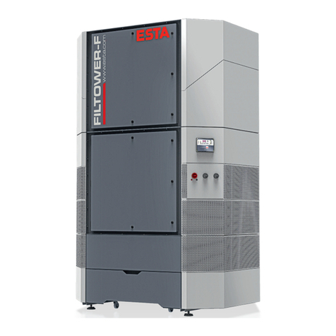
Esta DUSTOMAT 4-10 H User manual

Manual
DUSTOMAT 4 H
Fan Unit
ESTA Standard Control System
DUSTOMAT 4-10 H (order no.: 09,731)
DUSTOMAT 4-24 H (order no.: 09,761)
and variations
Manual
09731B-52-01

2
Fan unit standard control
09731B-52-01
Edition notice
Manual
Document no.: 09731B-52-01
Publishing date: 16.08.2015
Type of device: DUSTOMAT 4 H Fan unit ESTA standard control
Article no.: 09.731 // 09.761 and versions
Publisher
ESTA Apparatebau GmbH & Co. KG Tel.: +49 (0) 73 07 80 4 -0
Gotenstr. 2-6 Fax: +49 (0) 73 07 80 4 -500
Germany www.esta.com
Copyright notice (per DIN ISO 16016:2007-12)
Transfer or reproduction of this document, or the use or communication of its content, is forbid-
den without explicit consent. Violators will be liable for damages. All rights to patent, utility or
design registration are reserved.

Contents
09731B-52-01
Fan unit standard control
3
Contents
Contents.................................................................................................................................3
1. General instructions........................................................................................................4
1.1 Target group.............................................................................................................4
1.2 Tips ..........................................................................................................................4
2Product Description........................................................................................................4
2.1 Device image DUSTOMAT 4 H................................................................................4
2.2 Functional description ..............................................................................................5
2.3 Minimum volume flow monitoring.............................................................................6
3Safety................................................................................................................................7
3.1 Hazard categories....................................................................................................7
3.2 Symbol explanation..................................................................................................7
3.3 General safety instructions.......................................................................................8
3.4 Preventing electrical hazards ...................................................................................8
4Control system description............................................................................................9
4.1 ESTA Standard Control System control panel..........................................................9
5Faults/error messages..................................................................................................18
5.1 Possible error messages on the control panel........................................................18
5.2 Troubleshooting......................................................................................................21
Notes.....................................................................................................................................23

General instructions
4
Fan unit standard control
09731B-52-01
1. General instructions
1.1 Target group
This manual is intended for
Operators trained on the device who are familiar with the extraction process
Trained electrical specialists
Only change settings on the control unit with the support of ESTA customer ser-
vice
1.2 Tips
Read the instructions carefully before working with the device.
The device must be used only by persons who have been instructed in its han-
dling and are explicitly authorised to use it.
Always keep the instructions at the place where the device is being used, so that
they can be seen by personnel at all times.
2 Product Description
2.1 Device image DUSTOMAT 4 H
Filter unit
Fan Unit
Disposal unit
Control unit
Cleaning unit

Product Description
09731B-52-01
Fan unit standard control
5
2.1.1 Control unit ESTA standard control
2.2 Functional description
The control unit is integrated within the fan unit. The control unit is equipped with a
pressure sensor as a control device for overseeing minimum airflow volume. This
control device measures the negative pressure behind the filter unit. With in-
creased dust soiling of the filters in the filter unit, the flow resistance increases
along with the negative pressure behind the filter.
If the value set in the control system for the nominal volume flow is reached during
operation, this will be indicated by a message in the text field of the control panel.
At the same time, the filter cartridges are cleaned automatically with compressed
air. A pneumatic jet pulse cleaning device is integrated within the device's filter
unit for this very purpose. Intense pulses of compressed air are successively in-
troduced into the filter cartridges in the filter unit. The filters are freed from dust
and regenerated through this cleaning.
Control panel
Main switch
Signal

Product Description
6
Fan unit standard control
09731B-52-01
2.3 Minimum volume flow monitoring
The minimum volume flow is monitored through differential pressure measure-
ment. This is integrated into the control unit. If the nominal volume flow set at the
factory is fallen short of, the automatic cleaning of the filter cartridges begins. The
filter cartridges are automatically cleaned with compressed air. If the minimum
volume flow set in the device is reached, this will be indicated by a message in the
text field of the control panel and an acoustic signal. System shutdown and in-
spection is mandatory.
Extraction elements with various intake port diameters can be operated with the
device. When so doing, you must ensure that
The minimum airflow volume sucked away is not undershot.
- The minimum airflow volume depends on the diameter of the intake
port of the extraction element and the requisite conveying velocity.

09731B-52-01
Fan unit standard control
7
3 Safety
3.1 Hazard categories
Safety instructions and cross-topic information are indicated in this manual by
symbols.
Based on the severity of the hazard, the hazard warnings are categorized as fol-
lows:
DANGER
Hazard warning about an immediate danger to people.
Failure to comply can lead to severe injury or death.
WARNING
Warning about a recognisable hazard.
Failure to comply can lead to severe injury or death, and can destroy the device or
parts thereof.
CAUTION
Instruction about a hazard.
Failure to comply can lead to mild injury and to damage to the device.
3.2 Symbol explanation
Further information
Reference to ESTA customer service
Reference to legal regulations

Safety
8
Fan unit standard control
09731B-52-01
3.3 General safety instructions
In all emergencies, the device must be disconnected from the power supply im-
mediately, turned off at the main switch and the plug pulled immediately.
If there is a fire, alert the fire department immediately, and contain the fire by ap-
propriate means. Therefore keep a suitable extinguishing agent near the device
before start-up and during operation.
All movable machine parts driven by electric motors must be covered by fixed,
securely fastened protective covers that can be removed only with tools.
3.4 Preventing electrical hazards
DANGER
Electric shock from high voltages
Follow the safety rules for working with electrical devices!
Any work on the electrical grid and on voltage-conducting parts may only
be performed by an electrical specialist.
DANGER
Residual hazard from loose or open covers
Keep covers closed during operation!
Any work on the electrical grid and on voltage-conducting parts may only
be performed by an electrical specialist.
All electrical parts must be covered by fixed, securely fastened protective covers
that can be removed only with tools. The device complies with Protection Class I
according to DIN EN 60335.
After use, before moving the device to another site and before cleaning, mainte-
nance, or replacement or removal of movable parts, switch off the system at the
main switch and pull the mains connector.

09731B-52-01
Fan unit standard control
9
4 Control system description
4.1 ESTA Standard Control System control panel
Switch on the device at the main switch. The suction in manual mode is then
switched on and off by pressing the "ON/OFF" button.
1. Accessing the operation menu
2. Entering the ESC function in the menu
1. Navigation in the menus
2. Value adjustment
If held down, automatic value adjustment starts. The value increases if the
key is pressed down for an additional 5 seconds.
1. Beyond the menu functions:
Switching the extractor fan on and off / post-cleaning start
2. Within the menu function:
Selection / ENTER function
4.1.1 Operating on the control panel of the ESTA standard control
Once the device has been switched on at the main switch it is ready for opera-
tion. In this process the extractor fan is not activated.
Switching the suction operation on and off.
Display in suction operation.
Extractor fan: ON
DP filter = - 0.1 mbar
ESTA dust extractor
Ready for operation
Main switch
ON/OFF switch

Control system description
10
Fan unit standard control
09731B-52-01
After deactivation, the post-cleaning of the filter starts automatically. Then the
device switches back to a "ready for operation".
4.1.2 Menu selection / Operation menu
The normal user can only get into the operation menu in which he is able to op-
erate additional functions or open further information. The additional menu items
can only be accessed by production or ESTA service.
Operation menu:
The operation menu is accessed using the MODE button.
1. Sensor selection
Choice of which differential pressure sensor is displayed.
2. DP control filter
3. DP negative pressure
Change? -> ^
1. DP filter
2. Cleaning test
3. Drawer
4. Precoat. Function
5. Operating hours
6. Maintenance
7. Error messages
8. Button sound on/off
9. Language selection
10. Software version
11. Code entry
OPERATION MENU
1. Sensor selection
Post cleaning running
Valve number = 2

Control system description
09731B-52-01
Fan unit standard control
11
2. Cleaning test
The cleaning valves are activated with the current pulse and pause time. Clean-
ing runs until "test stop" is commanded with the ON/OFF button or until the menu
is exited.
5. Operating hours
The operating hours record the running time of the fan.
MODE button Menu function cancellation
6. Maintenance
The maintenance menu displays the hours set under minus the operating hours
under maintenance interval.
MODE button Menu function cancellation
8. Button sound on/off
There is a normal "good" sound and a "bad" sound, which indicates commands
that cannot be executed; such as selection and navigation at the end or start of
menus or value ranges.
Button sound: ON
Switch with ON / OFF
Button sound: OFF
Switch with ON / OFF
1998 h
until maintenance
Cleaning valve = 1
Test stop with ON / OFF
Cleaning: OFF
Test start with ON / OFF
Operating hours
= 2 h

Control system description
12
Fan unit standard control
09731B-52-01
9. Language selection
This is where you select the menu language.
10. Software version
Displays the software version with date.
11. Code entry
Code entry access to the service menu settings enables parameter settings to
be made without a hardware key. A 4-digit access code is required for this. If re-
quired, you can get this access code from ESTA customer services. The access
code is valid for at least one, and a maximum of two, operating hours after entry.
1. Value adjustment
If held down, automatic value adjustment starts. The value increases if the
key is pressed down for an additional 5 seconds.
2. Within the menu function:
Selection / ENTER function
3. Entering the ESC function in the menu
Code accepted!
MODE or ON/OFF
Please enter code
v ^ IIII ON/OFF
Software version
Vx.xx, x. MONTH 20xx
2. English
3. Spanish
4. French
Change?
1. German

Control system description
09731B-52-01
Fan unit standard control
13
In the event of the access code being entered incorrectly, the following message
appears.
1. Within the menu function:
Selection / ENTER function
2. Entering the ESC function in the menu
ESTA customer service: +49 (0) 7307 804 - 0
Incorrect access code!
MODE or ON/OFF

Control system description
14
Fan unit standard control
09731B-52-01
4.1.3 Service menu / Settings
Once the code entry has been successfully activated, the following settings can
be made.
Only do this with the support of ESTA customer service.
The following settings are linked to the
error messages below:
2. Upper threshold
3. Lower threshold
4. No. of valves
5. Pulse time
6. Pause time
7. Jet alarm threshold
8. Precoat. threshold
9. Post-clean. cycles
10. Brush maintenance
11. Brushing duration
12. Repetition
13. Start mode
14. Star start-up time
15. Wait Triangle
16. Fail-safe fault
17. Drawer aid
18. Control threshold
19. Neg. press. threshold
20. Motor control variable
21. Rem. ctrl overrun
22. Maintenance interval
23. Maintenance reset
24. Parameter reset
25. System message
Control filter full
Operation prohibited
SETTINGS
1. Type of cleaning

Control system description
09731B-52-01
Fan unit standard control
15
1. Value adjustment
If held down, automatic value adjustment starts. The value increases if the
key is pressed down for an additional 5 seconds.
2. Within the menu function:
Selection / ENTER function
3. Entering the ESC function in the menu
Jet alarm threshold exceeded
Check
suction power

Control system description
16
Fan unit standard control
09731B-52-01
4.1.4 Parameter list DUSTOMAT 4-10 H
The values in the following table apply as reference values for the configured pa-
rameters.
Here external losses of pressure that may occur through the connected pipeline
are not considered.
Parameter
Adjustment range
Set value at
ø125
Language selection
DE, EN, ES, FR, etc.
DE
1.
Type of cleaning
Brush / jet
Jet
2.
Upper threshold, clean-
ing
0 - 30 mbar
30
3.
Lower threshold, clean-
ing
0 - 30 mbar
30
4.
No. of valves
1 - 5
2
5.
Pulse time
0.0001 - 0.9999 sec
0.15
6.
Pause time
0.1 - 999.9 sec
3
7.
Jet alarm threshold horn
0 - 30 mbar
17
8.
Pre-coating threshold
0 - 30 mbar
0
9.
Post-cleaning cycles
0 - 20
6
13.
Start mode
Direct / star-delta / FC
Direct
14.
Star start-up time
0 - 60 sec
0
15.
Waiting time until delta
0 - 1000 ms
500
18.
Control filter threshold
0 - 30 mbar
12
19.
Negative pressure
threshold
0 - 60 mbar
23
20.
Motor control variable
0 - 100% (in 5% steps)
21.
Rem. ctrl overrun
0 - 60 min.
1
22.
Maintenance interval
0 - 10 h x 1000
2

Control system description
09731B-52-01
Fan unit standard control
17
4.1.5 Parameter list DUSTOMAT 4-24 H
The values in the following table apply as reference values for the configured pa-
rameters.
Here external losses of pressure that may occur through the connected pipeline
are not considered.
Parameter
Adjustment range
Set value at
ø160
ø180
ø200*
Language selection
DE, EN, ES, FR, etc.
DE
1.
Type of cleaning
Brush / jet
Jet
2.
Upper threshold, cleaning
0 - 30 mbar
20
19
17
3.
Lower threshold, cleaning
0 - 30 mbar
19
18
16
4.
No. of valves
1 - 5
2
5.
Pulse time
0.0001 - 0.9999 sec
0.15
6.
Pause time
0.1 - 999.9 sec
3
7.
Jet alarm threshold horn
0 - 30 mbar
21
8.
Pre-coating threshold
0 - 30 mbar
0
9.
Post-cleaning cycles
0 - 20
6
13.
Start mode
Direct / star-delta / FC
Direct
14.
Star start-up time
0 - 60 sec
0
15.
Waiting time until delta
0 - 1000 ms
500
18.
Control filter threshold
0 - 30 mbar
12
12
12
19.
Negative pressure threshold
0 - 60 mbar
31
29
26
20.
Motor control variable
0 - 100% (in 5% steps)
21.
Rem. ctrl overrun
0 - 60 min.
1
22.
Maintenance interval
0 - 10 h x 1000
2
* Standard

18
Fan unit standard control
09731B-52-01
5 Faults/error messages
5.1 Possible error messages on the control panel
1. Error messages
The system monitors the valve outlets for short-circuits and disconnection.
Monitoring only starts when a valve is activated.
2. Rotating field
The control system checks the rotating field of the feed every time the main
switch is activated. In the event of an incorrect field of rotation, this message ap-
pears and system operation is not possible. The rotating field must be changed.
To do this, switch the system off again on the main switch, and change the rotat-
ing field on the supply cable.
3. Motor fault
The input motor fault on the power unit is activated. The collective fault and horn
relays are triggered. The mains, star and delta contactor relays are deactivated.
Suction operation can only be switched back on once the motor fault has been
eliminated. The fault must be confirmed with the ON/OFF button.
Rotating field incorrect
Operation prohibited
The system is
fault-free
EMERGENCY OFF:
Motor fault

Faults/error messages
09731B-52-01
Fan unit standard control
19
4. Collective fault
An external contact at terminal 45, 46 leads to an EMERGENCY OFF message.
Operation is interrupted and can only be confirmed with the ON/OFF button. If
the external error message no longer exists, operation continues.
5. Valve error ;F
If ,F! is shown on the display after cleaning is performed in the Jet cleaning
cleaning mode, a valve error was detected during the cleaning process. A more
detailed description of the error is accessible in the operation menu in the sub-
menu error messages. If a valve error has occurred, cleaning is continued de-
spite the error. The cause of the error should be eliminated immediately.
The cause of this fault could be a severed cable or a defective valve.
The cause of this fault could be a short-circuit in the cable or valve.
6. Jet alarm threshold exceeded
This error message appears if the differential pressure over the filter continues to
increase despite cleaning being applied.
The message must be confirmed with the ON/OFF button. Then cleaning must
be started via the operation menu under the menu item cleaning test.
Jet alarm threshold exceeded
Valve number: X
fault: excess current
Valve number: X
Fault: interruption
XXXX ,F!
XXXX
EMERGENCY OFF: Input
Collective fault

Faults/error messages
20
Fan unit standard control
09731B-52-01
7. Control filter full
This message appears if the set threshold is exceeded. The collective fault and
horn relays are switched on. The message can be confirmed with the ON/OFF
button once the threshold is fallen short of.
8. Check suction power
This message appears when the negative pressure threshold is exceeded. The
collective fault and horn relays are switched on. The message is automatically
reset when the value falls below the threshold.
The message can be confirmed with the ON/OFF button. The pressure is
checked again after 10 seconds. If the threshold continues to be exceeded, the
error message re-appears.
9. Negative pressure exceeded
This message appears when the negative pressure threshold is exceeded at the
separate pressure switch. The device switches off. After that, the suction pipe
should be checked.
The message is to be confirmed with the ON/OFF button.
10. Please check your Parameter settings
One or more parameters are outside the permissible range. The error prevents
the activation of suction operation. The factory parameters can be set or com-
pletely re-established in the service menu settings. The relevant hardware key
or a code entry is required for this purpose.
Cancel with the MODE button.
PLEASE CHECK YOUR
PARAMETER SETTINGS
Negative pressure
exceeded
Check
suction power
Control filter full
Operation prohibited
This manual suits for next models
3
Table of contents
Other Esta Fan manuals
Popular Fan manuals by other brands
Vent-Axia
Vent-Axia GALAXY GDB Series Installation and wiring instructions
Sonnenkonig
Sonnenkonig JOVA 2 user manual
Evo
Evo VentCore 10-0800-VCMV Operator's manual
Hinkley
Hinkley INDY MAXX 99 instruction manual
Kipp & Zonen
Kipp & Zonen CVF4 instruction manual
ProKlima
ProKlima FN-110142.1 instruction manual
