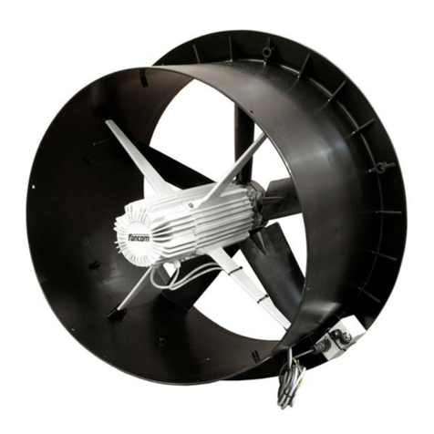
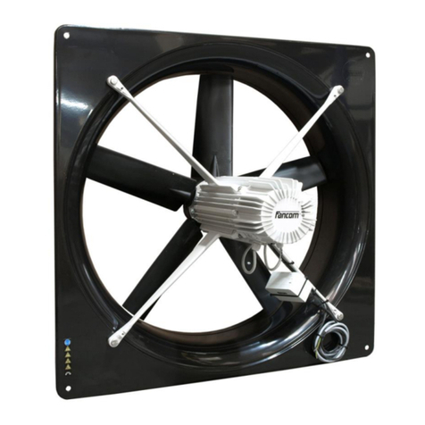
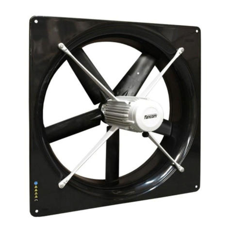
Fancom ATM80 User manual

AT(M)
MANUAL/HANDLEIDING/ANLEITUNG/NOTICE/MANUALE/
Руководство
VERSION A1

N.B.: The original, authentic version of this manual is the English version produced by Fancom B.V. or one of its
daughter companies (referred to further as Fancom). Any modifications introduced to this manual by third parties
have neither been checked nor approved by Fancom. Modifications are taken by Fancom to include translations
into languages other than English and the insertion and/or deletion of text and/or illustrations to/from the original
contents. Fancom cannot be held liable for any damages, injury, guarantee claims and other claims relating to
this type of modification, in as far as these modifications result in a content that differs from the original English
version of this manual produced by Fancom. For the latest information about product installation and operation,
please contact the customer service dept. and/or the technical service dept. of the Fancom concerned. In spite
of the care taken when compiling this manual, if you should discover any errors, please inform Fancom B.V. in
writing. Fancom B.V., PO Box 7131, 5980 AC Panningen (the Netherlands).
Copyright © 2020 Fancom B.V.
Panningen (the Netherlands)
All rights reserved. Nothing from this manual may be copied, distributed or translated into other languages, partly
or wholly, without express prior written permission from Fancom. Fancom reserves the right to modify this manual
without notice. Fancom can give no guarantee, neither implicit nor explicit, for this manual. All risks are for the
user.
This manual has been compiled with the utmost care. If, however, you should discover an error, please inform
Fancom B.V.
Art.Nr. 5911837
GB201117

Table of contents
1. General introduction ............................................................................................................................... 1
1.1 How to use this manual ............................................................................................................... 1
1.2 Symbols on the AT(M) ................................................................................................................. 1
1.3 Fancom Sales & Service Center ................................................................................................. 1
1.4 Safety instructions and warnings ................................................................................................. 1
2. Installing the AT(M) ................................................................................................................................. 3
2.1 Mount the AT(M) .......................................................................................................................... 3
2.2 Connect the AT(M) ...................................................................................................................... 5
2.3 Install the protective screen (optional) ........................................................................................ 6
2.4 Test the AT(M) ............................................................................................................................. 7
3. Using the AT(M) ....................................................................................................................................... 8
3.1 First use ....................................................................................................................................... 8
3.2 Maintenance ................................................................................................................................. 9
3.3 Disposal / recycling ...................................................................................................................... 9
4. Service .................................................................................................................................................... 10
4.1 Replace the AT motor ................................................................................................................ 10
4.2 Replace the DRS feedback sensor ........................................................................................... 10
5. Technical specifications ....................................................................................................................... 12
6. EC declaration of conformity ............................................................................................................... 13

1. General introduction
This manual has been created with the utmost care. If, however, you should discover an error, please inform
Fancom B.V..
1.1 How to use this manual
The following symbols are used in this manual:
Tips and suggestions.
Note providing recommendations and additional information.
Warning indicating damage to the product if you do not follow procedures carefully.
Warning indicating danger to humans or animals.
Electric shock hazard. Danger to humans and animals.
Example of a practical application of the described functionality.
Calculation example.
1.2 Symbols on the AT(M)
The following symbols are used on the AT(M):
Read the documentation and safety instructions which are provided in this user manual.
Warning indicating danger to the product or danger to humans or animals.
Moving parts can crush and cut.
Air flow direction.
1. Fancom Sales & Service Center
For any questions and support, please contact the local Fancom Sales & Service Center.
1.4 Safety instructions and warnings
Before installing and commissioning the AT(M), carefully read the separate safety document. This
contains safety instructions, provisions and conditions.
1

The installation of the device and remedying of any malfunctions should be performed by a certified
electrical installer according to the applicable norms.
The guarantee does not apply if the product is installed in any other way than is indicated by
Fancom and if the product's motor has been opened and changes have been made to the product.
Never install a damaged AT(M). A damaged AT(M) is unsafe because it may fall apart. Which as a
result can hurt humans and animals. Notify your supplier of any damages.
Parts of this product may have sharp edges. Wear safety gloves.
Do not touch any of the AT(M) moving parts.
Ensure that the workplace is clean and dry.
Notify your supplier of any damages.
2

2. Installing the AT(M)
Install the AT(M) and associated components as follows:
1. Mount the AT(M) (see (p. 3))
2. Connect the AT(M) (see (p. 5))
3. Install the protective screen (see (p. 6))
If the AT(M) is installed at heights less than 2.5 m above the floor and/or the AT(M) is within reach
of animals/humans then placement of a protective screen is necessary. Contact with rotating parts
of the AT(M), can cause serious to fatal injuries as result.
4. Test the AT(M) (see (p. 7))
The open position of the damper is factory adjusted. The closed position is automatically
calibrated during power up.
2.1 Mount the AT(M)
Mount the AT(M) in or on a solid structure with sufficient load-bearing capacity. Insufficient insight
into load-bearing capacity of the structure can cause the fall of the AT(M) with serious to fatal
injuries as a result.
Take into account the correct airflow direction.
Take the dimensions of various types of AT(M) into account when installing.
Type Ø A
mm
(inch)
B
mm
(inch)
Ø C
mm
(inch)
D
mm
(inch)
..35 440 (17.3) 393 (15.5) 362 (14.3) 350 (13.8)
..40 502 (19.8) 398 (15.7) 412 (16.2) 350 (13.8)
..45 565 (22.2) 404 (15.9) 462 (18.2) 350 (13.8)
..50 628 (24.7) 410 (16.1) 512 (20.2) 350 (13.8)
..56 702 (27.6) 418 (16.5) 572 (22.5) 350 (13.8)
..63 775 (30.5) 571 (22.5) 650 (25.6) 500 (19.7)
..80 985 (38.8) 595 (23.4) 813 (32.0) 500 (19.7)
35 - 56 63 - 80
C
A
B
D
B
C
A
D
3

2.1.2 Quick installation 5 - 80
Quick installation may only be done if the structure has exactly the same dimensions as the
underside of the module and is sufficiently solid.
1. Position the tube on the underside of the module. Take note that the openings through which the linking pins
go are directly across from each other.
2. Push the linking pins in so that the tube is connected to the module. If the linking pins can't be pushed in
completely (e.g. because they come in contact with the blades), then place them in the half-closed position.
Half-closed Closed
3. Secure the linking pins by screwing in a screw with lock washer from inside the tube into the linking pins.
Drilling
50 and 56 AT(M) in combination with CLICK extension tubes must be secured with 3 extra M4
bolts (M4 bolts spaced 120° from each other) in addition to the 3 standard linking pins.
3x
Install the protective screen
If the AT(M) is installed at heights less than 2.5 m above the floor and/or the AT(M) is within reach
of animals/humans then placement of a protective screen is necessary. Contact with rotating parts
of the AT(M), can cause serious to fatal injuries as result.
4

2.2 Connect the AT(M)
Before connecting, turn off the power and turn it back on only after the entire installation is ready.
If an end station controls more than one AT(M) unit (max. 3) in a parallel circuit, each AT(M) unit
must be wired directly from the end station. Do not wire from a connection box of one AT(M) unit to a
connection box of another AT(M) unit.
Make sure that the AT(M) is well and properly grounded according to the guidelines.
Keep signal and power cables as short as possible. If the length of the cable is longer than 40m, the
0V wire of the 24Vac power supply has to be connected double. Do this for all AT(M) units which are
connected to the same end station. The cable length may never exceed 100m.
The voltage and frequency data on the actuator identification plate must correspond to the power
supply.
Place cables preferably in a duct (separate signal cables from power supply cables).
Use low current cables for the electrical connection of the AT(M).
Connect the AT(M). Use the:
●Technical specifications (see (p. 5)).
The voltage and frequency data on the actuator identification plate must correspond to the power
supply.
●Connection diagram (see (p. 6)).
AT Control damper
Supply voltage 18-24Vac + 10% (ATM 35-56)
24Vac + 10% (ATM 63-80)
Power consumption 4W
Max. current 200mA
Control signal 10-0Vdc
Running time 90° angular rotation 22 sec. (ATM 35-56)
49 sec. (ATM 63-80)
Normal condition at delivery 0Vdc open, 8.5Vdc almost closed
Possibility to adjust the position at maximum control voltage
Transformer max. 16 actuators on 100VA transformer
PFB (Power Fail Box) max. 16 actuators on PFB
5

-
s
+
24Vac
24
IN
1 2
3
4
5 6
7
7
2
1
3
GND
*
(+) (-)
GND
IN
GND
24
GND
+ s -
white
brown
green
yellow
blue
red
black
Vortex damper
control
Direction Sensitive
RPM feedback
- DSR (ATM only)
Cable 7×0.14mm2
shielded
AT motor
Position feedback
Wiring connection
Alignment lock
Trimming
potentiometer
max. stroke
Connection box
Cable entry:
ATM 7×0.8mm
AT 4×0.8mm
Terminal strip
2. Install the protective screen (optional)
Turn the power supply off before cleaning or before carrying out any maintenance.
Before mounting the protective screen, make sure that the impeller is not turning.
6

Air inlet side
Install the protective screen on the AT(M) and secure it as shown in the illustration below:
2.4 Test the AT(M)
1. Check whether the AT(M) has been connected correctly.
2. Check whether the AT(M) works optimally.
Do not touch any of the AT(M) moving parts.
7

. Using the AT(M)
Before using the AT(M) you have to set the airflow measurement in the controller.
AT(M) 35-56
0
2.000
4.000
6.000
8.000
10.000
12.000
0
200
400
600 800 1.000 1.200
1.400 1.600 1.800
ATM 56
ATM 50
ATM 45
ATM 40
ATM 35
M3/h
(cfm)
RPM
AT(M) 63-80
0
5.000
10.000
15.000
20.000
25.000
0
200
400 600 800
1.000 1.200 1.400
ATM 80
ATM 63
M3/h
(cfm)
RPM
.1 First use
Do not touch any of the AT(M) moving parts.
Fancom advises to leave the AT(M) on for about 6 hours after installation, to let it run in.
8

.2 Maintenance
The AT(M) requires no specific maintenance. Fancom recommends that your installation technician inspects the
complete climate installation, of which the AT(M) is a component, every half-year.
Disconnect electrical power before inspecting or servicing equipment.
Inspect the AT(M) periodically for any damages.
Check the AT(M) for proper functioning regularly.
Fancom recommends that your installation technician inspects the complete climate installation, of
which the AT(M) is a component, every half-year.
.2.1 Cleaning
The AT(M) may be cleaned wet, but consider the following:
Do not use a high pressure hose or aim at motor seals or openings at close range.
Do not use water or high pressure cleaners for lengthy periods. The AT(M) contains rotating parts,
the throttle vanes. This means the construction is not completely waterproof. Water in the AT(M) can
cause mall funtions.
Do not turn the AT(M) during or after the cleaning process. Note that the air inlet side is always on
the bottom side.
After installation, there must always be power to the AT(M). This prevents the formation of
condensation in the AT(M).
. Disposal / recycling
When disposing the AT(M) please comply with all relevant requirements and regulations applicable in your
country.
9

4. Service
The following components of the AT(M) can be replaced:
●AT motor
●DRS feedback sensor
4.1 Replace the AT motor
For correct operation carry out instructions in the given order. If not, readjustment will be necessary.
1. Remove the plug from the connection box.
2. Place the entire AT(M) on the ground.
3. Unscrew the lid at the top and remove it. The AT motor can now be reached.
4. Disconnect the wiring from the AT motor (pay attention to the colour sequence) and then remove the AT motor.
5. Open the control dampers manually; check for smooth running.
6. Place the new AT motor and connect in the same way.
7. Replace the lid and tighten the screws.
8. Replace the unit.
9. Reconnect the plug to the connection box.
10. Check the AT(M) using the connected computer.
4.2 Replace the DRS feedback sensor
Ensure that there is a control of 100%, the AT control damper should be completely open. Also the output voltage
must be 0Vdc. If the AT control damper completely open, follow the procedure below.
1. Remove the plug from the connection box.
2. Place the entire AT(M) on the floor.
3. Unscrew the lid at the top and remove it. The AT motor and the DRS feedback sensor are now accessible.
4. Remove the AT motor, without disconnecting any connections. Position the motor so that the screw connection
of the DRS feedback sensor can be reached.
10

5. Replace the DRS feedback sensor.
<1mm
DSR feedback
sensor
Magnet
6. Place the AT motor. The control dampers should be still open.
7. Replace the lid, keeping the alignment lock in place.
8. Screw the lid on AT(M) (do not force it).
9. Reconnect the plug on the connection box.
10. Check if the system is functioning and re-adjust the AT control damper, if necessary.
11. Re-attach the AT(M) to the ventilation system.
Use the following technical specifications when replacing the DRS feedback sensor:
DRS feedback sensor
Supply voltage 8-18Vdc
Load (typical at 12V) min. 9.5mA, max. 15mA
Number of pulses per rotation 4
11

5. Technical specifications
Housing
ATM AT
Protection class IP55 IP55
Operating environment
Operating temperature range 0°C to +40°C
Storage temperature range -10°C tot 50°C
Relative humidity < 85%, not condensing
12

6. EC declaration of conformity
Manufacturer: Fancom B.V.
Address: Industrieterrein 34
City: Panningen (the Netherlands)
Hereby declares that the: AT(M)
Complies with the provisions of the:
1. Low voltage directive 2014/35/EU
according to EN-EN-IEC 60335-1:2012 + AC:2014 + A11:2014
2. Machine directive 2006/42/EC
3. EMC directive 2014/30/EU
Emission according to NEN-EN-IEC 61000-6-3: 2007
Immunity according to NEN-EN-IEC 61000-6-2: 2019
Place: Panningen
Date: 11/17/2020
Paul Smits
Managing Director
13

N.B.: De originele, authentieke versie van deze handleiding is de door Fancom B.V. of door een van haar
dochterondernemingen (verder aangeduid als Fancom) geproduceerde Engelstalige versie. Achteraf door
derden aangebrachte wijzigingen in deze handleiding zijn door Fancom noch gecontroleerd, noch goedgekeurd.
Onder wijzigingen verstaat Fancom o.a. het vertalen in een andere taal dan het Engels en het toevoegen en/of
verwijderen van tekst en/of illustraties aan/uit de originele inhoud. U kunt Fancom niet aansprakelijk stellen voor
schade, letsel, garantieclaims en andere claims die verband houden met dit soort wijzigingen, voor zover deze
wijzigingen resulteren in een inhoud die afwijkt van de authentieke door Fancom geproduceerde Engelstalige
versie van deze handleiding. Voor actuele informatie over productinstallatie en bediening neemt u contact op met
de klantenservice en/of technische serviceafdeling van de betreffende Fancom-onderneming. Mocht u onverhoopt
toch een fout ontdekken, dan vragen wij u vriendelijk Fancom B.V. hiervan schriftelijk in kennis te stellen. Fancom
B.V., Postbus 7131, 5980 AC Panningen (the Netherlands).
Copyright © 2020 Fancom B.V.
Panningen (the Netherlands)
Alle rechten zijn voorbehouden. Niets uit deze handleiding mag worden gekopieerd, gedistribueerd of vertaald
in andere talen, geheel of gedeeltelijk, zonder voorafgaande schriftelijke toestemming van Fancom. Fancom
behoudt zich het recht voor om wijzigingen in de handleiding aan te brengen. Fancom kan echter geen garantie
geven, impliciet noch expliciet, voor deze handleiding. Het risico hiervan ligt volledig bij de gebruiker.
Deze handleiding is met de grootst mogelijke zorg samengesteld. Mocht u onverhoopt toch een fout ontdekken,
dan vragen wij u vriendelijk Fancom B.V. hiervan in kennis te stellen.
Art.nr. 5911837
NL201112

Inhoudsopgave
1. Algemene inleiding .................................................................................................................................. 1
1.1 Hoe gebruikt u deze handleiding ................................................................................................. 1
1.2 Symbolen op de AT(M) ................................................................................................................ 1
1.3 Fancom Sales & Service Centre ................................................................................................. 1
1.4 Veiligheidsinstructies en -waarschuwingen .................................................................................. 1
2. De AT(M) installeren ................................................................................................................................ 3
2.1 Monteer de AT(M) ........................................................................................................................ 3
2.2 Sluit de AT(M) aan ...................................................................................................................... 5
2.3 Plaats het beschermrooster (optie) ............................................................................................. 6
2.4 Test de AT(M) .............................................................................................................................. 7
3. De AT(M) gebruiken ................................................................................................................................ 8
3.1 Eerste gebruik .............................................................................................................................. 8
3.2 Onderhoud ................................................................................................................................... 9
3.3 Afvoer/recycling ............................................................................................................................ 9
4. Onderhoud ............................................................................................................................................. 10
4.1 De AT-motor vervangen ............................................................................................................ 10
4.2 De RTTM-sensor vervangen ..................................................................................................... 10
5. Technische gegevens ........................................................................................................................... 12
6. EG-verklaring van overeenstemming .................................................................................................. 13

1. Algemene inleiding
Deze handleiding is met de grootst mogelijke zorg samengesteld. Mocht u onverhoopt toch een fout ontdekken,
dan vragen wij u vriendelijk Fancom B.V. hiervan in kennis te stellen.
1.1 Hoe gebruikt u deze handleiding
In deze handleiding worden de volgende symbolen gebruikt:
Tips en suggesties.
Opmerking met aanbevelingen en aanvullende informatie.
Waarschuwing duidend op schade aan het product als u procedures niet zorgvuldig uitvoert.
Waarschuwing duidend op gevaar voor mens of dier.
Kans op gevaarlijke elektrische schokken. Gevaar voor mens of dier.
Voorbeeld van een concrete toepassing van de beschreven functionaliteit.
Voorbeeld van een berekening.
1.2 Symbolen op de AT( )
De volgende symbolen worden gebruikt op de AT(M):
Lees de documentatie en veiligheidsvoorschriften behorend bij deze gebruikershandleiding.
Waarschuwing duidend op gevaar voor het product of gevaar voor mens of dier.
Bewegende onderdelen kunnen verbrijzelen en snijden.
Luchtstroomrichting.
1.3 Fancom Sales & Service Centre
Voor ondersteuning en antwoord op eventuele vragen kunt u het lokale Fancom Sales & Service Centre
raadplegen.
1.4 Veiligheidsinstructies en -waarschuwingen
Lees het veiligheidsdocument aandachtig door, voordat u de AT(M) installeert en in gebruik neemt.
Dit document omvat veiligheidsinstructies, bepalingen en voorwaarden.
1

De installatie van het apparaat en het verhelpen van eventuele storingen mag uitsluitend door een
erkend installateur te worden uitgevoerd volgens de geldende normen.
De garantie is niet van toepassing als het product op een andere wijze is geïnstalleerd dan door
Fancom is aangegeven en/of als de motor van het product is geopend en er wijzigingen aan het
product zijn aangebracht.
Installeer nooit een beschadigde AT(M). Een beschadigde AT(M) is onveilig omdat deze uit
elkaar kan vallen. Als gevolg daarvan, kunnen mens en dier gewond raken. Meld eventuele
beschadigingen aan uw leverancier.
Delen van dit product kunnen scherpe randen hebben. Draag veiligheidshandschoenen.
Raak de bewegende onderdelen van de AT(M) niet aan.
Zorg voor een schone en droge werkplek.
Meld eventuele beschadigingen aan uw leverancier.
2
Table of contents
Languages:
Other Fancom Fan manuals