ESTeem Edge 900 User manual

ESTeem Secure Wireless Networking
ESTeem User’s Manual
Edge 900
Manual Revision 2.0
May 2021

Electronic Systems Technology, Inc.
dba ESTeem Wireless Modems
415 N Roosevelt St; STE B
Kennewick, WA 99336
Phone: 509-735-9092
E-mail: market@esteem.com
Web Site: www.esteem.com
Copyright© 2021 by Electronic Systems Technology, Inc.
All rights reserved. Printed in the United States of America. No part of this publication may be reproduced, stored in a
retrieval system, or transmitted, in any form or by any means, electronic, mechanical, photocopying, recording, or
otherwise, without the prior written permission of Electronic Systems Technology.
Author:
Date:
Name:
Philip P. Marske
Title:
Product Specialist
Approved by:
Date:
Name:
Michael Eller
Title:
President

Edge 900
User’s Manual
Revised: 2 June 2021 ESTeem Edge 900
CHAPTER 1 –Introduction
Before You Begin
1
Edge 900 Overview
1
Steps to Programming Edge 900
2
CHAPTER 2 –Selecting Mode of Operation
Modes of Operation Overview
2
Network Diagrams
3
CHAPTER 3 –Installing Software
Install Discovery Utility
5
Edge 900 Configuration Utility
6
Basic Tab
---------------------------------------------
7
Serial Tab
---------------------------------------------
8
IP Access List
---------------------------------------------
8
Advanced
---------------------------------------------
8
Utilities
---------------------------------------------
9
Using Spectrum Analyzer
10
CHAPTER 4 –Programming Edge 900
Programming Edge 900
10
Step 1 –Find Best Frequency Channel
---------------------------------------------
10
Step 2 –Configure Master & Client Radios
---------------------------------------------
11
Step 3 –Test Radio Link
---------------------------------------------
11
Network Optimization
12
FCC Information
13
Edge 900 Antenna & Cable Configuration
14
Edge 900
User’s Manual
Revised: 2 June 2021 1 ESTeem Edge 900
Chapter 1 - Introduction
BEFORE YOU BEGIN
Thank you and congratulations on your purchase of the ESTeem Edge900 wireless
Ethernet radio! This manual was written to help both the first time and advanced
users of the Edge900 to configure the wireless radio for your application. If this is
your first time configuring the Edge900 and you would like to get going as soon as
possible, all product documentation and utilities can be found at the Getting
Started page of the ESTeem web site at www.esteem.com/gettingstarted.
The ESTeem Edge900 wireless networking hardware is a sophisticated networking
device. To keep the manual usably short, many of the application descriptions
and programming details assume the user has a good working knowledge of the
following network concepts:
•General Ethernet networking and the configuration of LAN topologies
•Common Ethernet terminology and acronyms
•TCP/IP network protocol structure and how to configure TCP/IP networks and
subnets.
•How to identify and set the TCP/IP address on your computer
•Have administrator privileges to the computer and network you are
configuring.
If you are unfamiliar with any of the above networking concepts, you may need to contact your network administrator for
assistance.
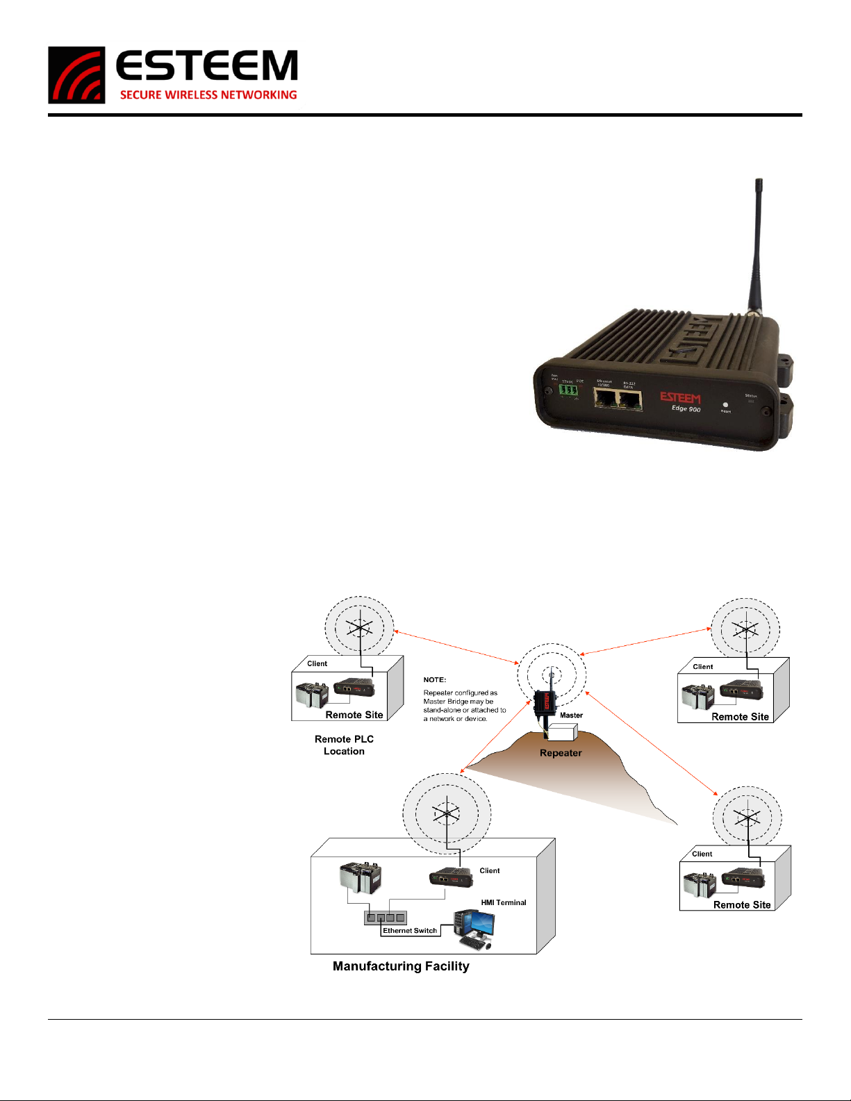
OVERVIEW
The Edge 900 is a wireless (radio)
modem operating in the unlicensed
900 MHz ISM band (902-928 MHz).
This simple to configure radio is used
to network Ethernet or legacy serial
devices at distances up to 10 miles
using a high security 256-AES
encryption. The Edge 900 is designed
to provide secure and reliable wireless
utilizing 13 discrete channels
throughout the 902-928MHz ISM Band.
Figure 1: ESTeem Edge900 Radio
Figure 2: General Example Application

Edge 900
User’s Manual
Revised: 2 June 2021 2 ESTeem Edge 900
STEPS TO PROGRAMMING EDGE 900
The programming of the Edge 900 radio is completed in three simple phases:
1) Select Mode of Operation
The Edge900 radio will come by default in Client mode. Most of the radios in your system will be in this mode but one must
be in Master mode for the clients to connect to. If you are going in the field, you can select Analyzer mode to run the
spectrum analyzer and select the best channel for operations. If the radios are being installed, you can select Alignment
mode which sets the radios into a point-to-point configuration that rapidly sends packets back and forth and displays the
RSSI in the Discover Suite allowing quick and easy antenna alignment.
2) Install Programming Software
The Edge900 configuration software is contained within our Discovery Suite software and can be downloaded for free from
our website (www.esteem.com/esteem-utilities/). It is a Java based program and needs NPCAP to function so both of those
utilities need to be installed for the software to function properly. Once both are installed you can run the utility and
Discover your radio.
3) Program Radios
Once you have selected your Mode of Operation you can configure the other needed settings, Channel, Network ID, and
Passphrase. Mode detailed information on these settings can be found further in the manual. Once you have a Master and
a Client with matching Channel, Network ID, and Passphrase settings they will start communicating. It is that easy!
Chapter 2 –Selecting Mode of Operation
The Edge 900 Radio will allow programming for any of the 4 modes of operation: Master, Client, Alignment, or Analyzer. Two modes
of operation (Master and Client) are used for operating the radio and the Alignment and Analyzer modes are used for setup and
troubleshooting. Every network will consist of a single Master with one or more Client radios. The Alignment and Analyzer modes
are used in helping to setup and configure the radios. When set up, the network will always be a “hub and spoke” based network
with the Master in the center (Hub) and the Client(s) as end points (Spoke). If a repeater is needed in the network the Master will be
required to take a that position, only the Master can communicate directly with multiple radios.
1) Master
Every Edge 900 radio network needs one radio set to Master to function. The Master is the main point of communication for all
Client radios in the network. The Master will have a direct connection to all clients and as such should be the main location in the
network unless a repeater is needed. If a repeater is required only the Master mode radio can act as this repeater. Two Master
radios cannot communicate over an RF link to each other.
2) Client
The most common mode of operation for the Edge900 radio will be Client. Clients will connect to a Master radio with the same
Network ID and Passphrase on the same frequency channel. A Client cannot communicate with another Client radio directly, they
must talk through a Master radio.
3) Analyzer
The Analyzer Mode is a powerful tool for setting up your Edge 900 network. It includes most of the basic functions of a Spectrum
Analyzer but is isolated to the 902-928 MHz Band. This mode allows you to monitor the received signal levels at the current location
of the configured Edge 900 radio. This allows you to see which channel would best suit your network at each location.
4) Alignment
The Alignment Mode is a specialized tool to help maximize the installation of a point-to-point radio system. When 2 radios are in
Alignment Mode one radio will constantly report the RSSI from the other radio. This helps with making sure the Client radio’s
antennas are aligned properly back to the Master radio’s antenna.

Edge 900
User’s Manual
Revised: 2 June 2021 3 ESTeem Edge 900
Network Diagrams
The configuration of the Edge 900 is
very simple in that there are only two
communication modes of operation, as
either a Master or Client. Every Edge
900 network will have a single Master
with one or more Clients. The following
network diagrams cover most
applications.
Figure 4: Point to Point with Repeater Example
Figure 3: Point to Point Example

Edge 900
User’s Manual
Revised: 2 June 2021 4 ESTeem Edge 900
Figure 6: Multipoint Network with Repeater Example
Figure 5: Multipoint Network Example
Edge 900
User’s Manual
Revised: 2 June 2021 5 ESTeem Edge 900
Chapter 3 –Installing Software
ESTeem Discovery Suite
The ESTeem Discovery Suite will allow configuration of the IP address on the Edge 900 radio to match the network regardless of its
current IP subnet. The Discovery Utility will also allow access to the Edge 900 Configuration Utility for programming and
troubleshooting the wireless network.
Installation
The Discovery Utility can be downloaded from the ESTeem web site (https://www.esteem.com).
1. The Discovery Suite is a Java™ based application compatible with any computer operating system that can run Java (Window,
Linux, etc). The application requires two (2) additional support files to operate:
Java Runtime Utility –Downloadable from https://www.java.com or Open JDK. The version required will be based upon your
operating system.
Note: The installation and updates from Java may try and install additional web browser toolbars. Uncheck the optional
installation if they are not desired.
Npcap –Downloadable from https://nmap.org/download.html. Be sure to download the latest Stable release for your operation
system.
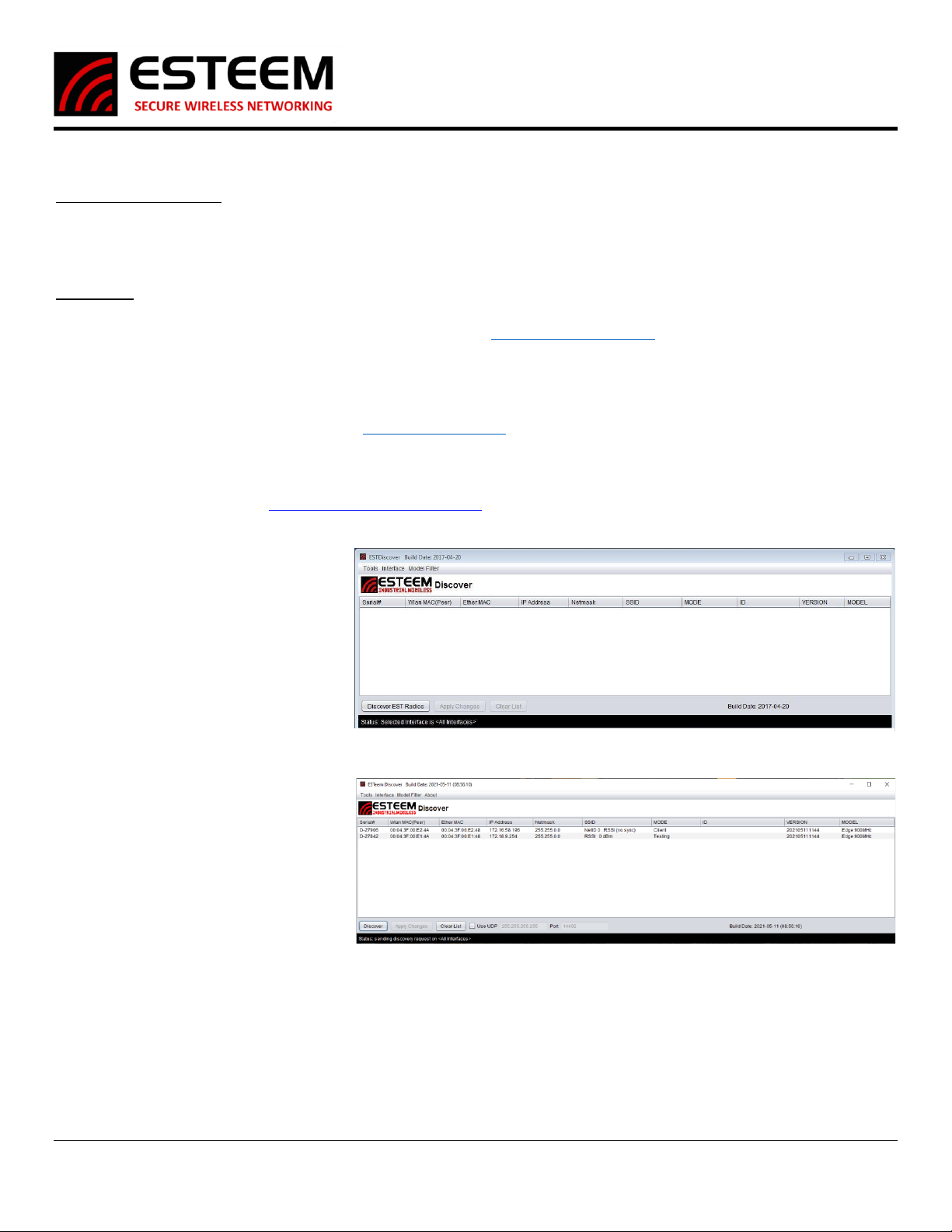
2. Once both the above programs have
been installed, save the ESTDiscover.exe
file to any location on your computer
such as the Desktop. Double click the
ESTeem.exe program and Figure 7 will be
displayed.
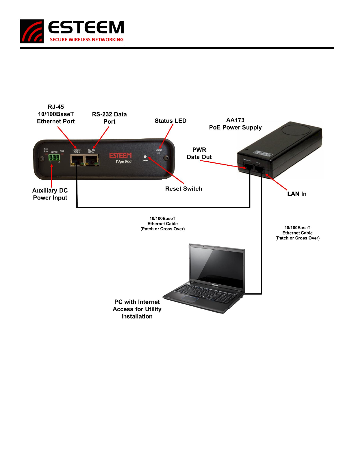
3. Connect the Edge 900 modem to your
computer either directly to the Ethernet
card or through a Switch using an
Ethernet cable. The Ethernet port
supports Auto-Negotiation, so either a
patch cable or crossover cable will work.
Press the Discover button.
4. The ESTeem Edge 900 will be displayed
(Figure 8). If the ESTeem Edge 900 is not
on the same IP subnet as the computer,
double click on the IP and/or Netmask
and make the necessary changes. Press
the Apply Changes button when
complete.
Figure 7: EST Discovery Suite
Figure 8: Radio Discovered
Edge 900
User’s Manual
Revised: 2 June 2021 6 ESTeem Edge 900
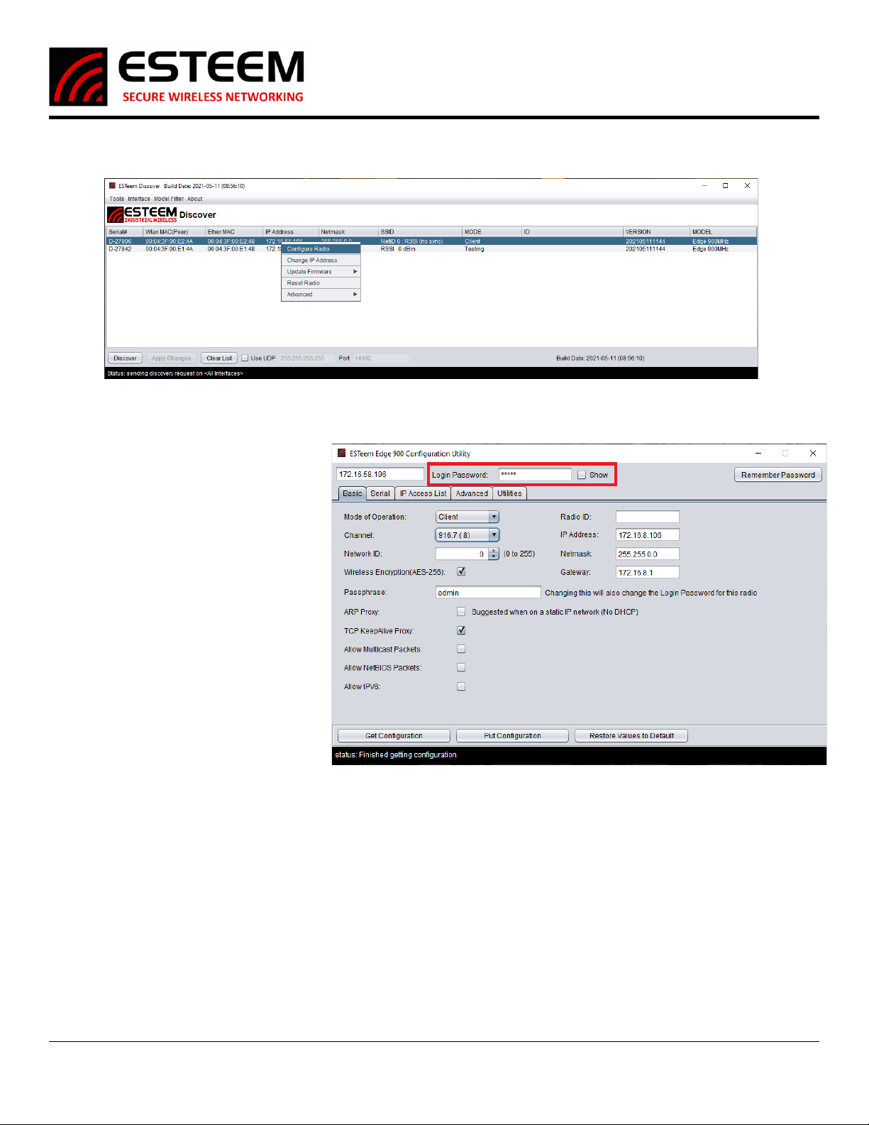
5. If changes were made to the IP address, you will need to press the Discover button again to show the changes after the radio has
rebooted. Right-mouse click on the Edge and select Configure Radio button to begin programming.
Edge 900 Configuration Utility
The Edge 900 Configuration Utility will allow
programming of the ESTeem Edge900 radio
only. There are some features to the
Configuration Utility that remain static
throughout the configuration of the radio,
those are as follows.
Menu Top
IP Address, Password, and Remember
Password Button: The IP Address should be
set to the radio you are attempting to
configure. For the first time configuring a
radio the password should be “admin”
(without the quotes). If it’s not your first time
configuring the radio the password will be the
passphrase you set earlier. The Remember
Password sets the password currently in the
password field to remain there after the
Configuration Utility has been closed and
reopened.
Menu Bottom
Get Configuration, Put Configuration, and Restore Values to Default Buttons: The Get Configuration attempts to connect to an
Edge900 radio using the IP and Password set at the top of the utility, once connected it then fills in the Utility with the configuration
of that radio. The Put Configuration button does the exact opposite, it first connects to the radio using the IP and password at the
top of the utility then puts all the settings in the Utility into the radio. If the IP Address or Password is changed in this way you will
have to update the utility before continuing. The Restore Values to Default button changes all current settings in the Utility to their
factory default settings. This does not set the radio to factory default settings unless Put Configuration is used immediately after.
NOTE: For increased security, the pass phrase for the network must be entered to change the configuration on any Edge 900 radio. By
default, this passphrase is set to admin from the factory.
Figure 9: Configure Radio
Figure 10: Edge 900 Configuration Utility
Edge 900
User’s Manual
Revised: 2 June 2021 7 ESTeem Edge 900
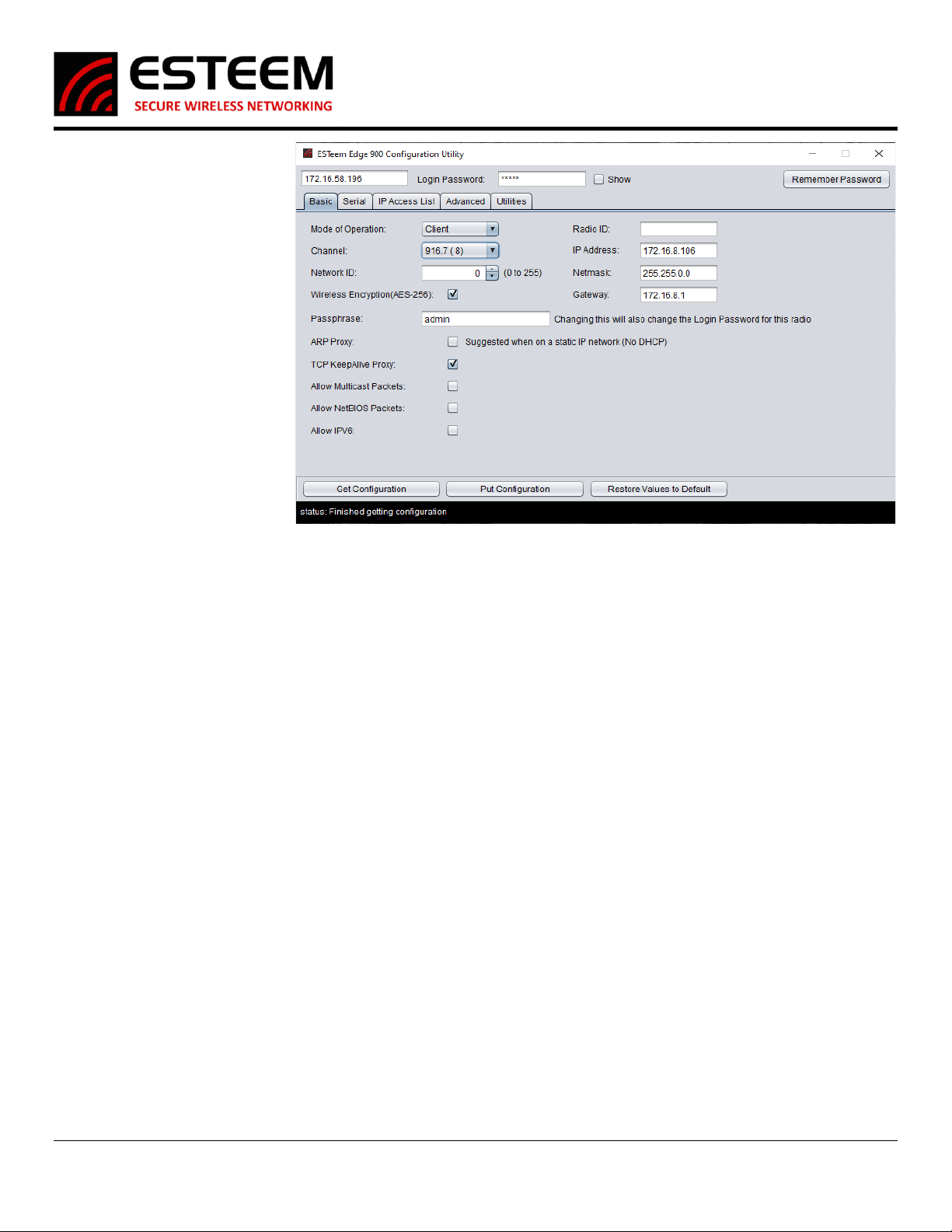
Basic Tab
Most of the configuration that you
will do happens here on this first
page. Many of the important
settings that determine which
radios will communicate are set
here. Details of the settings
available on this page can be found
below.
Mode of Operation: This setting
will set which mode this radio will
operate in. Master, Client,
Analyzer, or Alignment.
Channel: This will set the operating
frequency of the radio. You can
select a number between 1 and 13
or using the arrows raise and lower
the operating channel.
Network ID: This will set the
Network ID of this radio; this allows
radios of the same Network ID to
communicate with each other. If 2 radios have different Network IDs they will not communicate. The Network ID can be a number
between 0 and 255.
Passphrase: This sets the password that is needed to connect to the radio with the Configuration Utility as well as the password that
the radios use to communicate with each other. This passphrase can be at most a 64-character length combination of numbers,
letters, or special characters.
Radio ID: This is simply an identifier that helps differentiate between radios. This will only show up on the Discovery and in the
Configuration Utility. This Radio ID can be at most 11 characters long.
IP Address: This sets the IP Address of the radio that you are currently configuring. This can be set to any valid IPv4 address.
Netmask: This sets the Netmask of the radio that you are currently configuring. This can be set to any valid IPv4 address.
Gateway: This sets the Gateway of the radio that you are currently configuring. This can be set to any valid IPv4 address.
Wireless Encryption: This option turns on/off the need for a password for RF communication. This setting needs to be the same on
all radios that will be communicating with each other.
ARP Proxy: This setting turns on/off the ARP Proxy of the radio. Address Resolution Protocol or ARP packets help “map” out a
network. These packets happen often and use up precious RF Bandwidth so the radio will keep track of successful ARP packets and
act as a proxy answering ARP requests without passing the packet over the air. If you have a static network that does not have
equipment changes it is recommended to leave this setting on. If devices will move around or change IP Addresses often this setting
should be disabled.
TCP KeepAlive Proxy: This setting turns on/off the TCP KeepAlive Proxy. PLCs using Ethernet communication send out a “KeepAlive
Packet” every few seconds to make sure the other PLCs are there. Enough of these KeepAlive packets and you cannot even get data
through. This proxy works identically to the ARP Proxy, after a successful packet the radio will keep track of who answers. Future
packets will then be answered by the radio and not passed over the RF.
Allow Multicast Packets: This allows (if enabled) and does not allow (if disabled) multicast packets to pass over the RF. By default,
this is disabled and unless the use of these radios requires multicast packets it is recommended to remain disabled.
Allow NetBIOS Packets: This allows (if enabled) and does not allow (if disabled) NetBIOS packets to pass over the RF. By default, this
is disabled and unless the use of these radios requires NetBIOS packets it is recommended to remain disabled.
Allow IPv6: This allows (if enabled) and does not allow (if disabled) IPv6 packets to pass over the RF. By default, this is disabled and
unless the use of these radios requires IPv6 packets it is recommended to remain disabled.
Figure 11: Basic Tab
Edge 900
User’s Manual
Revised: 2 June 2021 8 ESTeem Edge 900
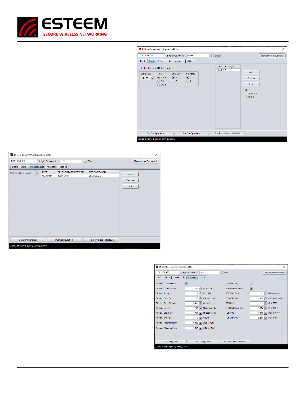
Serial Tab
This tab will only be needed if you are going to be using
the RS-232 Data Port on the radio. This tab allows the
enable/disable of the serial port along with its
configuration. You can configure the Baud Rate, Parity,
Data Bits, and Stop Bits. When setting up the serial port
you will have to set the destination IP Addresses of the
radios you intend to communicate with, not the serial
devices on the other end. You can Add, Remove, and
Modify any IP Addresses using the appropriately named
buttons on this tab. By default the 224.0.0.1 IP Address
is in the list, this is a multicast IP Address and will be
sent to everyone connected to this radio.
IP Access List Tab
The IP Access List if enabled on this tab will stop all
communication from going over the RF if the IP Address of
the Source does not match an IP Address found on the IP
Access List. By default this setting is enabled and allows
traffic within the radio’s default Netmask. New addresses
can be added, modified, or removed as necessary by using
the so-named buttons. There are 3 options when entering
IP Addresses into the Access List; Single, Range, and
Netmask. The single option is just that, a single IP Address
added to the Access List. The Range option allows you to
enter a start IP and end IP to create a range of allowed IP
Addresses. The Netmask allows you to enter an IP and
Netmask of all IP Addresses you want to allow to
communicate over the RF.
Advanced Tab
The Advanced tab has many settings that are automatically
adjusted based on the Mode of Operation set on the basic tab.
These settings should not be changed unless informed by
ESTeem Customer Support. Changing these settings could have a
negative effect on the operation of the radio.
Figure 12: Serial Tab
Figure 13: IP Access List
Figure 14: Advanced Tab
Edge 900
User’s Manual
Revised: 2 June 2021 9 ESTeem Edge 900
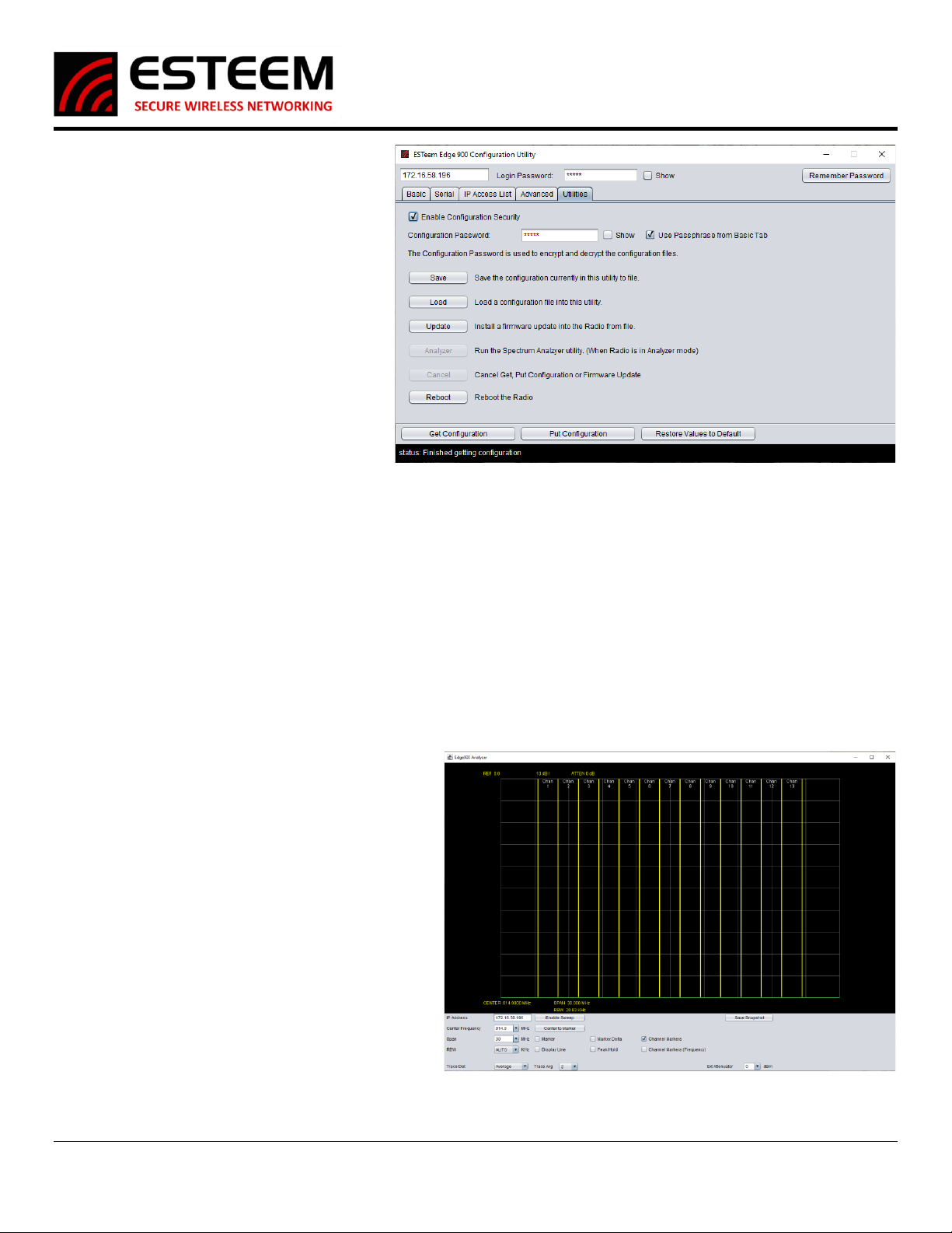
Utilities Tab
The Utilities tab has many helpful tools for
maintaining and configuring the radios. The first
options on this page are for configuration security.
The Edge900 Configuration Utility can save a copy
of the settings of an Edge900 radio to a file on your
computer. If the Enable Configuration Security
option is enabled this configuration file will be
encrypted. If it’s disabled it is saved in plain text.
The password needed to encrypt and decrypt the
file can be manually configured here under
Configuration Password, by default all of this is
enabled and it uses the passphrase from the basic
tab as the password. The other options on this
page are as follows;
Save: This button saves a copy of the configuration of
this radio to a file on your computer. A window will pop up asking you to save the file to a selected location.
Load: This opens a window asking for the location of a config file saved using the above button. When the file is selected all the
settings on the previous tabs (Basic, Serial, IP Access List, and Advanced) will be changed to match that of the file. Don’t forget to Put
the Configuration into the radio using the Put Config afterwards.
Update: This allows you to update the firmware of the radio using an ESTeem supplied image file.
Analyzer: This opens the Edge900 Analyzer program. If the radio is not in Analyzer mode, it will not respond to requests from this
Analyzer program.
Cancel: If the radio you are attempting to communicate with has stopped responding, you can use this button to force the utility to
stop attempting to Get/Put the Configuration or stop an Update of the firmware.
Reset: This Reset button sends a reboot command to the radio. This is as if you powered down then back up the radio.
Spectrum Analyzer
The Spectrum Analyzer built into the Edge900 is a very
helpful and simple tool that can be used before setup to
help determine the best operation frequency and during
operation to help troubleshoot problems like other
wireless signals operating on or near the frequency the
radios are configured for. The Spectrum Analyzer window
is a 10x10 grid that displays Frequency across the X Axis
and Signal Strength across the Y axis. The Frequency
display can be adjusted with the Center Frequency and
Span options at the bottom of the analyzer, by default
each grid square is 3MHz wide. The Signal Strength Y axis
cannot be adjusted with the top of the window being 0 dB
and the bottom being -100 dB each grid square is 10dB
wide. The Analyzer can be customized with the following
settings.
IP Address: This should be set to that of the Edge900 in
Analyzer mode you are using to sweep.
Center Frequency: This will set the center frequency of the analyzer. You can select the different
channels of the Edge900 with the drop-down arrow or type in a specific number.
Figure 15: Utilities Tab
Figure 16: Spectrum Analyzer

Edge 900
User’s Manual
Revised: 2 June 2021 10 ESTeem Edge 900
Span: This sets the total width of the analyzer, by default a span of 30MHz is set which makes each of the 10 column segments 3MHz
wide. For a more focused view of lower the span to “zoom in” on a specific section of frequency.
RBW: This sets the RBW of the analyzer and is recommended to stay set at AUTO.
Trace Det & Trace Avg: This sets the Trace Det and Trace Avg and is recommended to stay at Average and 2 respectively.
Ext Attenuator: If external attenuation is being used currently, the program can compensate for that and display the actual signal
strength by changing this setting to match the attenuation being used.
Enable Sweep: This button turns on and off the sweeping of the frequency. If the span or frequency is changed the enable sweep
will need to be turned off and on again to see those changes.
Center to Marker: If a marker has been set on the analyzer this button will move the center frequency to that of the marker.
Marker: Checking this box then clicking on the analyzer window will place a marker that can be dragged around with the mouse. This
helps identify a specific frequency and signal strength. Once the marker is placed in the upper right and corner of the window it will
display the frequency and signal strength at that marker point.
Marker Delta: The Marker Delta works with the Marker in that 2 points can be placed on the analyzer. Once the Marker is placed
and a Marker Delta is placed the Delta will display the difference in frequency and signal strength between the Marker and the
Delta.
Display Line: This puts a line that runs the whole span of the analyzer and displays the signal strength of that line on the right side of
the window. This can also be dragged up and down in the window.
Peak Hold: If this is selected instead of constantly updating the current signal strength of the whole analyzer it will instead only
display the strongest signal detected at a specific frequency and hold that display.
Channel Markers & (Frequency): By default, Channel Markers is enabled showing yellow lines that are the different operating
channels of the Edge900 radio. If Channel Markers (Frequency) is selected it will also display the operating frequency at the top of
the window.
Save Snapshot: This will save a picture of the analyzer window as the button is pressed. A window will pop-up asking where you
would like to save the file. Do not forget to give it a proper image format name. (Example: snapshot.PNG)
Chapter 3 –Programming the Edge900 Radio
Step 1 –Find the best channel with the Analyzer Mode
If you have already had an RF Site Survey done
and know the best available channels for you
setup you can skip to step 2. After powering up
and connecting to the radio with the Edge900
Configuration Utility set the Mode of Operation to
Analyzer. Then press Put Configuration at the
bottom, the radio will reboot in Analyzer Mode.
Step 1.1 –Opening the Analyzer –After the radio
is in Analyzer Mode you can access the Analyzer
program two different ways.
Through the Discovery Suite –Right-click on the
Edge900 radio in Analyzer Mode and under
Advanced-> Select Edge900 Spectrum Analyzer.
Through the Configuration Utility –On the Utilities
tab select the Analyzer button to open the
Spectrum Analyzer Program.
Step 1.2 –Using the Analyzer –The Edge900
Spectrum Analyzer Program is a very simple but helpful tool for determining the best possible frequency of operation. It is
recommended to have Peak Hold and Channel Markers enabled to see overtime communication on specific channels. The center
frequency can be changed, span and add external attenuation if required. There is also a display line and channel marker delta.
Figure 17: Setting Analyzer Mode
Edge 900
User’s Manual
Revised: 2 June 2021 11 ESTeem Edge 900
When saving a snapshot do not forget to add the image extension .PNG to the file name so you can view the file as an image later. A
more detailed description of the Analyzer can be found further in the manual.
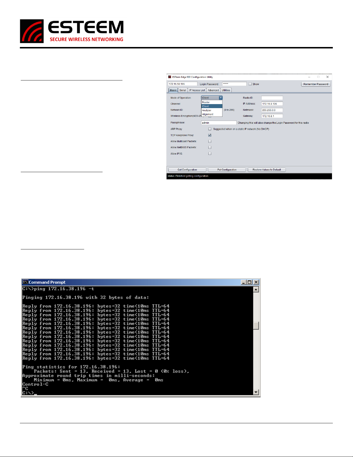
Step 2 - Configure Master and Client Radios
Edge900 radio networks are made up of one (1) master and
any number of client radios. The client radios will connect
to a master but not to other clients. When connecting, the
client will only connect to a master that shares a Channel,
Network ID, and Passphrase. If any of these settings are
changed, they will not connect and communicate.
Once all the radios are configured a pre-installation test is
always recommended, remember to have the antennas
connected and put as much distance between the radios as
you can.
Step 3 –Alignment and Installation
Once the radios have been installed, use the receive signal
strength readings from the Discovery Suite to align the
antennas. If you have a point-to-point link you can use the
Alignment Mode to align the antennas if as needed. It is not
a required step but can help achieve the best results of the radios. To use this mode simply connect to the radios with the
Configuration Utility and switch the radio into Alignment mode. The radio will retain its settings on the basic page as you switch
between modes of operation. Once the radios have been set to Alignment mode, open the RSSI Monitor in the Discovery Suite to
watch a 1 second interval update of the RSSI between these 2 radios. *Tip* Stick to 2 radios at a time, the master, and a single client.
Once that client has achieved the best RSSI, set it back to client mode and move to the next client.
Testing Wireless Data Links
The easiest method for testing the efficiency of data flow between the Edge 900 radios is to conduct a Ping test to the opposite
radio’s IP address. An Ethernet Ping utility is available in most TCP/IP computer’s operating system and is entered at the command
prompt. See operating system documentation or IT support for further detail.
Figure 19: Ping Test
Figure 18: Master or Client Configuration

Edge 900
User’s Manual
Revised: 2 June 2021 12 ESTeem Edge 900
NETWORK OPTIMIZATION
The most common problem experienced using a wireless network is data overload. The Ethernet network attempts to use more
bandwidth than the wireless network has available. The Edge 900 has a maximum RF data rate of 1 Mbps that must be shared
between multiple remote locations. The limited bandwidth available requires that the radio incorporate multiple tools to mitigate
the data overflow and optimize the wireless network for different Ethernet network requirements.
Limiting Ethernet Data Traffic
By default, the Edge 900 is configured as a wireless bridge device that will attempt to pass all Ethernet traffic received across the
wireless network. If the Edge 900 radios are connected to a busy office or plant network, it is very easy to overload the limited
bandwidth of the radio. The following tools help restrict the most common types of Ethernet network management data packets
sent over an office or plant network that can easily overload the wireless network:
Enable/Disable Multicast IP –This option will allow the user to select if multicast traffic (from IP addresses starting with 224.X.X.X or
239.X.X.X) to pass over the wireless bridge. Some industrial Ethernet devices communicate using multicast traffic and can easily
overload the wireless network. To remove multicast traffic from the wireless network, uncheck the “Enable Multicast IP” box in the
Master Bridge configuration. The Remote Bridge will receive this configuration setting from the Master Bridge and does not require
any other settings.
Enable Netbios Filter - This option will allow transfer of all Microsoft NetBIOS information to pass across the wireless bridge link of
Edge 900 radios. This Microsoft Windows based computer management frames are generally not required in most TCP/IP based
networks and only unnecessarily take up wireless bandwidth. To remove NetBIOS traffic and greatly reduce the data load on
Ethernet networks connected to Windows based computers, uncheck this box when configuring the Master Bridge.

Edge 900
User’s Manual
Revised: 2 June 2021 13 ESTeem Edge 900
FCC Information to Users
The equipment has been tested and found to comply with the limits for both the FCC Class B digital device (pursuant to Part 15 of the
FCC rules) and Industry Canada (IC) CAN ICES-3 (B)/NMB-3(B).
FCC Statement
Operation is subject to the following two conditions: (1) This device may not cause harmful interference, and (2) this device must
accept any interference received, including interference that may cause undesired operation.
Caution: Changes or modifications to this equipment not expressly approved by ESTeem Wireless Modems for compliance could
void the user's authority to operate the equipment.
IC Statement
“This device complies with Industry Canada licence-exempt RSS standard(s). Operation is subject to the following two conditions: (1)
this device may not cause interference, and (2) this device must accept any interference, including interference that may cause
undesired operation of the device.”
“Cet appareil est conforme avec Industrie Canada exempts de licence standard RSS (s). Son fonctionnement est soumis aux deux
conditions suivantes: (1) cet appareil ne doit pas provoquer d'interférences et (2) cet appareil doit accepter toute interférence, y
compris celles pouvant causer un mauvais fonctionnement de l'appareil.”
Emissions Information
Edge 900 MHz (Model 217ES)
HVIN: 217ES
DTS Spread Spectrum Device
(USA) FCC ID: ENPEDG217ES
(Canada) IC No: 2163A-217ES

Edge 900
User’s Manual
Revised: 2 June 2021 14 ESTeem Edge 900
Edge 900 MHz Antenna and Cable Configurations
ESTeem offers different types of antennas for both indoor and outdoor configurations. This device has been designed to operate
with the antennas listed below, and having a maximum gain of 7 dB. Antennas not included in this list or having a gain greater than 7
dB are strictly prohibited for use with this device. The required antenna impedance is 50 ohms.
This radio transmitter ESTeem Edge 900 MHz (HVIN: 217ES) has been approved by Industry Canada to operate with the antenna types
listed below with the maximum permissible gain and required antenna impedance for each antenna type indicated. Antenna types
not included in this list, having a gain greater than the maximum gain indicated for that type, are strictly prohibited for use with this
device.
Le present emetteur radio ESTeem HVIN: 216AD a ete approuve par Industrie Canada pour fonctionner avec les types d'antenne
enumeres ci-dessous et ayant un gain admissible maximal et l'impedance requise pour chaque type d'antenne. Les types d'antenne non
inclus dans cette liste, ou dont le gain est superieur au gain maximal indique, sont strictement interdits pour l'exploitation de l'emetteur.
Warning: Only the tested cable lengths and antennas provided by EST meet the FCC and DOC maximum peak output power
requirements. Any other combination of antennas or coax cables is not authorized. To reduce potential radio interference to
other users, the antenna type and its gain should be so chosen that the equivalent isotropically radiated power (e.i.r.p.) is not
more than that permitted for successful communication.
Part Number: AA20DMEs
•Omni-directional direct mount antenna, 2 dBi gain.
•Indoor and outdoor applications.
•There must be a minimum separation distance of 23
cm. from the antenna to the user. See Warnings.
Part Number: AA20Es900
•Omni-directional external pole mount antenna, 7 dBi
gain with 3-ft. integral feedline and connector.
•Outdoor applications.
•There must be a minimum separation distance of
23cm. from the antenna to the user. See Warnings.
Part Number: AA206Es900
•Directional pole mount antenna, 11 dBi gain with
1.5-ft. integral feedline and connector.
•Point to point and point to multi-point outdoor
applications.
•There must be a minimum separation distance of 23
cm. from the antenna to the user. See Warnings.
Warnings:
Only pre-made coax cables from the factory used in
conjunction with either the AA20Es900 omni-directional and
AA203Es900 directional antennas meet all FCC Section
15.247(b) EIRP maximum power requirements.
Transmit/Receive
Antenna Port

Edge 900
User’s Manual
Revised: 2 June 2021 15 ESTeem Edge 900
Edge 900 Specifications
Transmiter/Receiver
Frequencyof Operation 902-928 MHz
RF Data Rate 1 Mbps
TxOutput Power (Software Selectable) 24dBm
TxOutput Impedance 50 ohms
RxSensitivity -97 dBm
FCC Type Acceptance ENPEDG217ES
IndustryCanada Type Acceptance 2163A-217ES
LED Indicators Power (On/Off) - Carrier Detect (On/Off) - Transmitter (On/Off) - Reveiver (On/Off)
Power Requirements
Receive 160mA@ 12 VDC
Transmit 700mA@ 12 VDC
PoE Power Supply (IEEE 802.3at,30 watts) (opt)
External Power Input 10 to 16 VDC @ 1A
Input/Output Connectors
Ethernet Port 1 (10/100/1000) RJ-45 Female
RS-232C Comm Port (2,400 to 115.2 K baud) RJ-45 Female
Antenna Input/Outputs TNC Reverse Female
External DC Input Power Mini-Combicon, 3 pin female
Case
Temperature Range -30° to +60° C
Humidity 95% Non-condensing
Dimensions 1.9 in. H x6.7 in. W x6.2 in. L
Weight 1.25 lbs.
Product Warranty 1 Year
Other
Outdoor Pole Mt. Kit AA195PM(opt)
PoE Power Supply AA175.2 (opt)
ESTeem Edge 900 Specifications
Edge 900
User’s Manual
Revised: 2 June 2021 16 ESTeem Edge 900
Edge 900 Configuration Layout

Edge 900
User’s Manual
Revised: 2 June 2021 17 ESTeem Edge 900
Other manuals for Edge 900
3
Table of contents
Other ESTeem Radio manuals


