WNI Global Challenger L Series User manual

Challenger L Series
User Reference and Installation Manual
WNI Global INC.
VERSION:2.0

This manual is provided by WNI Global and its confidentiality is preserved. Without the pre-written consent from WNI Global, anyone
may not disclose, extract, cite or publish any part or all parts of this manual. Version No.: V2.0
Table of Contents
1
SYSTEM DESCRIPTION.......................................................................................................................1-1
1.1
About This Manual..........................................................................................................................................1-1
1.2
Introduction .....................................................................................................................................................1-1
1.3
System Features...............................................................................................................................................1-4
1.4
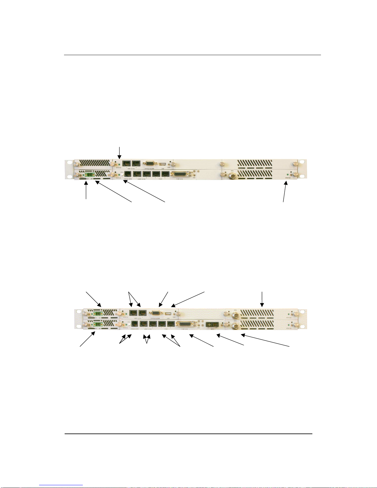
Physical Description........................................................................................................................................1-5
1.4.1
Front Panel Indicators................................................................................................................................1-6
1.4.2
Front Panel Connections............................................................................................................................1-6
1.5
System Description........................................................................................................................................1-10
1.6
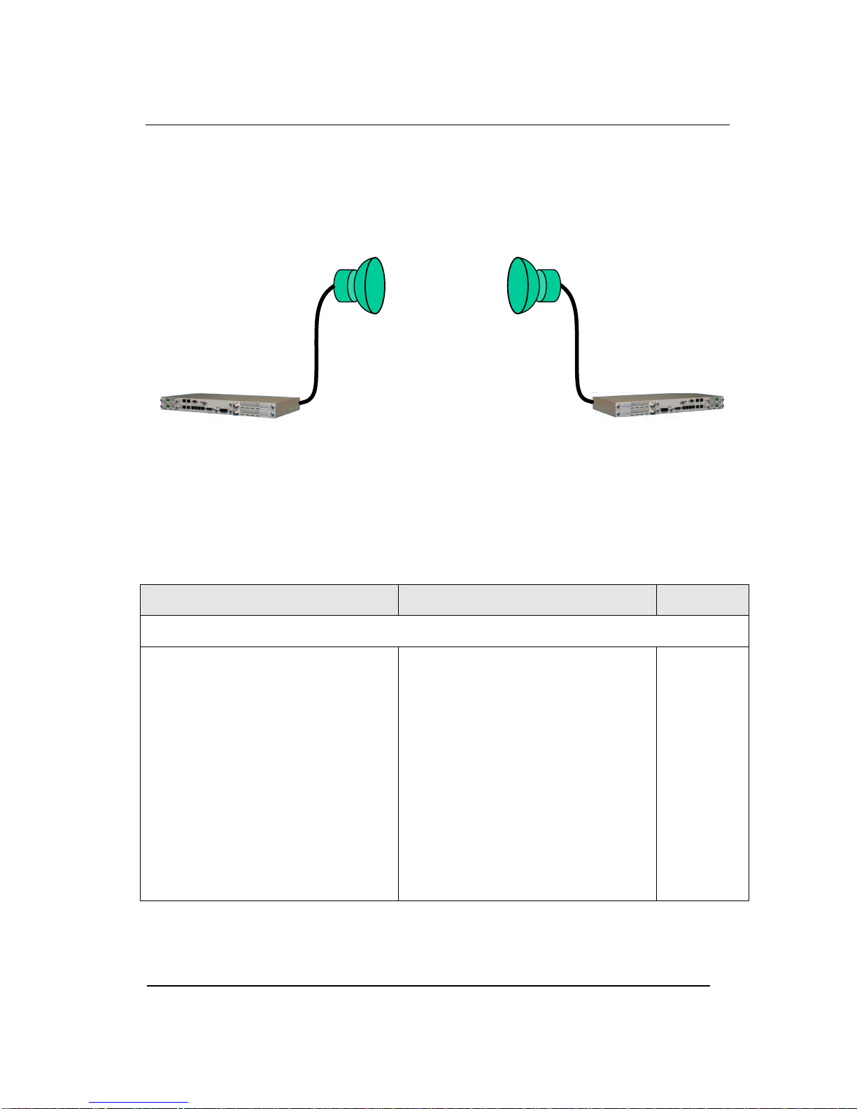
Consecutive Point Architecture....................................................................................................................1-13
1.7
Power Management.......................................................................................................................................1-15
1.8
Network Management...................................................................................................................................1-16
1.9
ODU data........................................................................................................................................................1-16
1.9.1
Feature Summary.....................................................................................................................................1-16
1.9.2
ODU Specification summary...................................................................................................................1-17
1.9.3
IDU Software Selectable Capacities........................................................................................................1-18
2
INSTALLATION...................................................................................................................................2-19
2.1
Unpacking ......................................................................................................................................................2-19
Challenger L ODU ..................................................................................................................................................2-19
2.2
Notices.............................................................................................................................................................2-20
2.3
PRE-INSTALLATION NOTES...................................................................................................................2-21
2.3.1
Back-to-Back Bench Testing...................................................................................................................2-21
2.4
Overview of Installation and Testing Process.............................................................................................2-22
2.5
Site Evaluation...............................................................................................................................................2-23
2.5.1
Preparing for a Site Evaluation................................................................................................................2-24
2.5.2
Site Evaluation Process............................................................................................................................2-25
2.5.3
Critical System Calculations....................................................................................................................2-27
2.5.4
Documenting a Site Evaluation ...............................................................................................................2-29
2.6
Installation of the Challenger L Digital Radio............................................................................................2-32
2.6.1
Installing the Challenger L IDU ..............................................................................................................2-32
2.6.2
Preparing for ODU Installation................................................................................................................2-33
2.6.3
Routing the ODU/IDU Interconnect Cable..............................................................................................2-35
2.6.4
Connecting the Challenger L IDU to the PC and Power Source .............................................................2-36
3
SUMMARY SPECIFICATION................................................................................................................3-1
4
FRONT PANEL CONNECTORS...........................................................................................................4-1

Challenger L Series Digital Microwave Production User Manual
iii This manual is provided by WNI Global and its confidentiality is preserved. Without the pre-written consent from WNI Global, anyone
may not disclose, extract, cite or publish any part or all parts of this manual. Version No.: V2.0
4.1
DC Input (Power) Connector .........................................................................................................................4-1
4.2
Challenger L Ethernet 100BaseTX Payload Connector...............................................................................4-1
4.3
Challenger L STM-1 Payload Connector......................................................................................................4-2
4.4
Challenger L E-3 Payload Connector............................................................................................................4-2
4.5
NMS 10/100BaseTX Connector......................................................................................................................4-2
4.6
ODU Connector ...............................................................................................................................................4-5
4.7
E1- Channels 1-2 Connector...........................................................................................................................4-5
4.8
E1- Channels 3-16 Connector.........................................................................................................................4-6
5
SOFTWARE OPERATION ....................................................................................................................5-1
5.1
Interface Mode:................................................................................................................................................5-1
5.2
How to access Challenger L IDU....................................................................................................................5-1
5.2.1
Local Access..............................................................................................................................................5-1
5.2.2
Telnet Access.............................................................................................................................................5-2
5.3
Customer Interface..........................................................................................................................................5-3
5.3.1
Overview ...................................................................................................................................................5-3
5.3.2
Customer Interface.....................................................................................................................................5-6
6
APPENDIX.............................................................................................................................................6-1
6.1
Abbreviations & Acronyms............................................................................................................................6-1
6.2
Conversion Chart ............................................................................................................................................6-4


602-13068-01
1 System Description
1.1 About This Manual
This manual is written for those who are involved in the “hands-on” installation of the WNI Global
Digital Radio, such as installation technicians, site evaluators, project managers, and network
engineers. It assumes the reader has a basic understanding of how to install hardware, use
Windowsbased software, and operate test equipment.
1.2 Introduction
The Challenger L digital radios provide high capacity transmission, flexibility, features, and
convenience for wireless digital communications networks. The Challenger L series digital point-
to-point radios represent a new microwave architecture that is designed to address universal
applications for both PDH and SDH platforms. This advanced technology platform is designed to
provide the flexibility to customers for their current and future network needs.
The Challenger L series equipment is based upon a common platform to support a wide range of
network interfaces and configurations. It supports links for 16 x E1, E-3, 1/2 x 100BaseTX
Ethernet, and 1 x STM-1. The radio family is spectrum and data rate scalable, enabling service
providers or organizations to trade-off system gain with spectral efficiency and channel availability
for optimal network connectivity. Challenger L series digital radio enables network operators
(mobile and private), government and access service provides to offer a portfolio of secure,
scalable wireless applications for data, video, and Voice over IP (VoIP).
The Challenger L digital radio family is composed of a Challenger L Indoor Unit and Outdoor
Unit (ODU). The Challenger L IDU is designed to be frequency independent, and the ODU is
designed to be capacity independent. The Challenger L IDU allows selection for multiple
capacity options, modulation types, radio frequency channels and transmit output power
levels to accommodate and adhere to world-wide regulatory and spectral efficiency
requirements. The companion ODU, mounted outdoors, can support frequency bands from
7 to 38 GHz.
The Challenger L IDU supports 1+0 and 1+1 protection and ring architectures in a single 1
RU chassis. The modem and power supply functions are supported using easily replacable
plug-in modules. An additional feature of the Challenger L IDU is provision for a second
plug-in modem/IF module to provide repeater or east/west network configurations.
The Challenger L Digital Radio includes integrated Operations, Administration, Maintenance, and
Provisioning (OAM&P) functionality and design features enabling simple commissioning when the
radio network is initially set up in the field at the customer’s premises. Furthermore, a highlight of
Challenger L radio products is scalability and the capability to support a ring-type architecture.

Challenger L Series Digital Microwave User Manual
1-2 This manual is provided by WNI Global and its confidentiality is preserved. Without the pre-written consent from WNI Global,
anyone may not disclose, extract, cite or publish any part or all parts of this manual. Version No.: V2.0
This ring or consecutive point radio architecture is self-healing in the event of an outage in the link
and automatically re-routes data traffic, thereby ensuring that service to the end user is not
interrupted.
The overall architecture consists of a single 1RU rack mount Challenger L Indoor Unit with a
cable connecting to an Outdoor Unit (ODU) with an external antenna.
Figure 1-1. Challenger L IDU/ODU Architecture
Table 1-1 lists key features that Challenger L technology offers to those involved in the design,
deployment and support of broadband fixed wireless networks.
Table 1-1. Key Benefits and Advantages of Challenger L Digital Radios
Benefits Advantages to Providers/Customers Reference
Challenger L Indoor Unit
Universal signal processing platform
Advanced Single Chip Modem ASIC
Integrated Forward Error Correction (FEC)
Powerful adaptive equalizer
Enables easy network interface options
and network capacity growth in the future.
Cost effective solution; simplifying product
logistics and overall product life cycle
costs. The flexibility reduces capital and
operating expenditures commonly
associated with field installation,
maintenance, training and spares.
Frequency independent and Scalable.
Software defined flexibility enables
selective modulation for spectral efficiency
and adherence to world-wide regulatory
emissions guidelines.
1.2 – 1.5
IDU
ODU
IF cable
Antenna
IDU
ODU
IF cable
Antenna

1-3 This manual is provided by WNI Global and its confidentiality is preserved. Without the pre-written consent from WNI Global, anyone
may not disclose, extract, cite or publish any part or all parts of this manual. Version No.: V2.0
Table 1-1. Challenger L Digital Radio Benefits and Advantages to Providers
(continued)
Benefits Advantages to Providers/Customers Reference
Easy to install units
Straightforward modular system enables
fast deployment and activation.
Carrier-class reliability.
Fast return on investment.
No monthly leased line fees.
2.1, 2.4, 2.6
Complete support of payload capacity with additional voice orderwire
Aggregate capacity beyond basic network
payload.
Scalable and spectrally efficient system.
Separate networks for radio
overhead/management and user payload.
Increases available bandwidth of network.
Allows customer full use of revenue-
generating payload channel.
Lowers total cost of ownership.
1.2 – 1.5
Ring Architecture
Supports a ring (consecutive point)
configuration, thus creating a self-healing
redundancy that is more reliable than
traditional point-to-point networks.
In the event of an outage, traffic is
automatically rerouted via another part of
the ring without service interruption.
Ring/consecutive point networks can
overcome line-of-sight issues and reach
more buildings than other traditional
wireless networks.
Networks can be expanded by adding
more Challenger L Digital Radios or more
rings without interruption of service.
A separate management channel allows
for a dedicated maintenance ring with
connections to each Challenger L Digital
Radio on the ring.
Enables network scalability.
Increases deployment scenarios for initial
deployment as well as network expansion
with reduced line-of-sight issues.
Increases network reliability due to self-
healing redundancy of the network.
Minimizes total cost of ownership and
maintenance of the network.
Allows for mass deployment.
1.6

Challenger L Series Digital Microwave User Manual
1-4 This manual is provided by WNI Global and its confidentiality is preserved. Without the pre-written consent from WNI Global,
anyone may not disclose, extract, cite or publish any part or all parts of this manual. Version No.: V2.0
Table 1-1. Challenger L Digital Radio Benefits and Advantages to Providers
(continued)
Benefits Advantages to Providers/Customers Reference
Adaptive Power Control
Automatically adjusts transmit power in
discrete increments in response to RF
interference.
Enables dense deployment.
Simplifies deployment and network
management.
1.7
Comprehensive Link/Network Management Software
A graphical user interface offers security,
configuration, fault, and performance
management via standard craft interfaces.
Suite of SNMP-compatible network
management tools that provide robust
local and remote management capabilities.
Simplifies management of radio network
and minimizes resources as entire network
can be centrally managed out of any
location.
Simplifies troubleshooting of single radios,
links, or entire networks.
Simplifies network upgrades with remote
software upgrades.
Allows for mass deployment.
1.5, 1.8
1.3 System Features
Selectable Rates and Interfaces
oPDH Options
Up to 32 x E1
100BaseTX/Ethernet: Scalable 5-100 Mbps
E-3
oSDH Options
1 x SDH STM-1
Support for multiple configurations for both PDH and SDH
o1+0, 1+1 protection
oHot Standby

1-5 This manual is provided by WNI Global and its confidentiality is preserved. Without the pre-written consent from WNI Global, anyone
may not disclose, extract, cite or publish any part or all parts of this manual. Version No.: V2.0
oEast/West Repeater
Selectable Spectral Efficiency of 0.8 to 6.25 bits/Hz (including FEC and spectral shaping
effects)
QPSK, 16 –256 QAM Modulation
Powerful Trellis Coded Modulation concatenated with Reed-Solomon Error Correction
Built-in Adaptive Equalizer
Support of Voice Orderwire Channels
Peak output power: +24 dBm (will vary with ODU and frequency plan)
Receive Sensitivity: -70 dBm (or lower, depending on data rate/modulation/FEC/ODU)
Adaptive Power Control
Built-in Network Management System (NMS)
Consecutive Point ring architecture
Built-in Bit Error Rate (BER) performance monitoring
1.4 Physical Description
The following section details the physical features of the Challenger L digital radios
•Model Options
•Front and rear panel configurations
•LED descriptions

Challenger L Series Digital Microwave User Manual
1-6 This manual is provided by WNI Global and its confidentiality is preserved. Without the pre-written consent from WNI Global,
anyone may not disclose, extract, cite or publish any part or all parts of this manual. Version No.: V2.0
1.4.1
Front Panel Indicators
All models of the Challenger L Digital Radios support a variety of front panel configurations that
are dependent on the network interface and capacity configurations.
Figure 1-2 provides an example of the PDH 8/12/16 E1 1+0 configuration and the associated
LEDs displayed on the Challenger L IDU front panel.
Figure 1-2. Challenger L IDU LEDs: Front Panel, 1+0 Configuration
1.4.2
Front Panel Connections
Please refer to the Figure 1-3 for an example of a Challenger L IDU front panel followed by a
descriptive text of the connections.
Figure 1-3. Challenger L IDU, 1+1 Protection: Front Panel Connections
Power/Fault LED
Power Input
Status LED
Status LED
Status LED
Power
Input
Redundant
Power
-
Supply
NMS Ethernet
ALARM/Serial
Interface (Optional)
Voice
Orderwire
Call Button &
Interface
Connection
Ethernet
Data
Connections
2xE1
Connections
8/16x E1
Connections
ODU
Connection
Redundant
MODEM
Power
Input
NMS Ethernet
Voice
Orderwire
Call Button &
Interface
Connection
Ethernet
Data
Connections
Connections
Connections
ODU
Connection
USB
STM-1
Connection
(Optional)

1-7 This manual is provided by WNI Global and its confidentiality is preserved. Without the pre-written consent from WNI Global, anyone
may not disclose, extract, cite or publish any part or all parts of this manual. Version No.: V2.0
The recommended maximum length for all cables to terminal equipment is a maximum of 3
meters. The exception to this recommendation is the length of the ODU/IDU Interconnect cable,
which connects the Outdoor Unit to the Indoor Unit.
Power Supply Input
DC Input
-48 VDC
-48v (Isolated Input); 2-pin captive power connector. The
Challenger L Digital Radio requires an input of -48 volts dc
±10% at the front panel DC Input connector. The total
required power is dependent on the option cards and
protection configuration (1+0, 1+1). The Challenger L IDU
front panel power connector pin numbering is 1 through 2,
from left to right, when facing the unit front panel. Pin 1 is the
power supply return and is connected to unit chassis ground
internally. Pin 2 should be supplied with a nominal -48 V dc,
with respect to the unit chassis (ground). A ground-isolated
supply may be used, provided it will tolerate grounding of its
most positive output.
The recommended power input is -44 to -52 V dc at 2 Amps
minimum. It is recommended that any power supply used be
able to supply a minimum of 100 W to the Challenger L IDU.
A mating power cable connector is supplied with the
Challenger L IDU. It is a 2-pin plug, 5 mm pitch, manufactured
by Phoenix Contact, P/N 17 86 83 1 (connector type MSTB
2,5/2-STF). This connector has screw clamp terminals that
accommodate 24 AWG to 12 AWG wire. The power cable
wire should be selected to provide the appropriate current with
minimal voltage drop, based on the power supply voltage and
length of cable required. The recommended wire size for
power cables under 10 feet in length supplying -48 Vdc is 18
AWG.
The Challenger L IDU supplies the ODU with all required
power via the ODU/IDU Interconnect cable. The Challenger L
IDU does not have a power on/off switch. When DC power is
connected to the IDU, the digital radio powers up and is
operational. There can be up to 320 mW of RF power present
at the antenna port (external antenna version). The antenna
should be directed safely when power is applied.

Challenger L Series Digital Microwave User Manual
1-8 This manual is provided by WNI Global and its confidentiality is preserved. Without the pre-written consent from WNI Global,
anyone may not disclose, extract, cite or publish any part or all parts of this manual. Version No.: V2.0
Alarm/Serial Interface
Alarms/Serial DB-15HD female connector for two Form-C relay alarm
outputs (rated load: 1A @ 24 VDC), two TTL alarm outputs,
four TTL alarm inputs, and Serial Console. The two Form-C
relay alarm outputs can be configured to emulate TTL alarm
outputs.
USB Interface
USB USB connector, optional.
Voice Orderwire Connector
Voice
Orderwire
Call
Call button to alert operator at link-partner Challenger L IDU of
incoming Voice-Orderwire call.
Voice
Orderwire RJ-11 modular port connector for voice orderwire interface.
NMS 10/100 Network Management System Connections
10/100 10/100Base-TX RJ-45 modular local port connector for access
to the Challenger L Network Management System (SNMP).
Challenger L-100/Ethernet Models: Ethernet 100BaseT Connections
100Base-TX 100Base-TX RJ-45 modular port connector for the local Fast
Ethernet interface.
E1 Channels
E1 1-2 Two E1 (RJ-48C) interface connections.
E1 3-8/16 Single Molex 60-pin connector containing 14 E1 connections,
or DB-26HD 26-pin connector containing 6 E1 connections.

1-9 This manual is provided by WNI Global and its confidentiality is preserved. Without the pre-written consent from WNI Global, anyone
may not disclose, extract, cite or publish any part or all parts of this manual. Version No.: V2.0
STM-1 Connection
STM-1Out BNC connector for the STM-1 electrical interface.
SC connector for the STM-1 optical interface.
STM-1 In BNC connector for the STM-1 electrical interface.
SC connector for the STM-1 optical interface.
E-3 Connection
E-3 Out BNC connector for the E-3 interface.
E-3 In BNC connector for the E-3 interface.
ODU/IDU Interconnect
To ODU TNC female connector. Used to connect the Challenger L
ODU to the Challenger L IDU. Provides –48VDC and 350
MHz Transmit IF to the ODU and receives 140 MHz Receive
IF from the ODU.
Ground Connection
Ground On optional ground stud may be installed on the front panel.

Challenger L Series Digital Microwave User Manual
1-10 This manual is provided by WNI Global and its confidentiality is preserved. Without the pre-written consent from WNI Global,
anyone may not disclose, extract, cite or publish any part or all parts of this manual. Version No.: V2.0
1.5 System Description
The overall digital radio architecture consists of a single 1RU rack mount Challenger L Indoor Unit
with a cable connecting to an Outdoor Unit (ODU) with an external antenna.
SWITCH
CPU
SNMP
2x 100BASE-TX
User
2x 100BASE-TX
16x E1
Voice
2x100 Mbps
2x100 Mbps*
16x 2.048 Mbps
64 Kbps
E3
155.52 Mbps
FRAMER
MODEM/FEC ASIC
Modulation:
BPSK - 256-QAM
Adaptive Equalization:
17 Taps
FEC:
TCM + Reed Solomon
Serial
Digital
IF
Optional I/O Cards
(Small Slot):
Standard I/O
East/Primary Modem
STM-1
34.368 Mbps
Primary Power Supply
Secondary Power Supply
Multiplexed
Signal to ODU
-48 Vdc
-48 Vdc
Modem
Control/
Telemetery
IDU Controller
Quad
Mux
MODEM/FEC ASIC
Modulation:
BPSK - 256-QAM
Adaptive Equalization:
17 Taps
FEC:
TCM + Reed Solomon
Digital
IF
West/Secondary Modem
Multiplexed
Signal to ODU
Quad
Mux
SWITCH
ROH Serial
Figure 1-4. Challenger L IDU Block Diagram
Figure 1-4
shows the
Challenger L IDU
and interfaces from a functional point of view. The functional
partitions for the I/O, Modem/IF, and power supply modules are shown. The
Challenger L IDU
comes
with the standard I/O capability which can be upgraded. In addition, the Modem/IF function is
modular. This allows the addition of a second Modem to support protection or ring architectures. The
power supply is similarly modular.
The major functions of the
Challenger L IDU
can be summarized as follows:
•I/O Processing – The
Challenger L IDU
comes with a standard I/O capability that includes
support for up to 16xE1 and 2x100Base-TX user payloads, 2x100Base-TX for SNMP, and voice
orderwire. In addition, option cards for E3, 1xSTM-1 may be added. The
Challenger L IDU
architecture is flexible and allows for the addition of other I/O types in the future.

1-11 This manual is provided by WNI Global and its confidentiality is preserved. Without the pre-written consent from WNI Global,
anyone may not disclose, extract, cite or publish any part or all parts of this manual. Version No.: V2.0
•Switch/Framing – The
Challenger L IDU
includes an Ethernet Switch and a proprietary Framer
that are designed to support 1+1 protection switching, ring architecture routing, and overall
network control functions.
•Network Processor – The
Challenger L IDU
includes a Network Processor which performs SNMP
and Network Management functions.
•Modem/IF – The
Challenger L IDU
Modem performs forward-error-correction (FEC)encoding,
PSK/QAM modulation and demodulation, equalization, and FEC decoding functions. The IF chain
provides a 350 MHz carrier and receives 140 or 60 MHz carriers. The multiplexer function is built
into an appliqué that resides in the Modem/IF Module. Two modems can be used for 1+1
protection or ring architectures.
•Power Supply – The
Challenger L IDU
power supply accepts
-
48 Vdc and supplies the
Challenger L IDU
and ODU with power. A second redundant power supply may be added as an
optional module.
The Modem Processor and its associated RAM, ROM, and peripherals control the digital and analog
Modem operation. It also provides configuration and control for both the IF and I/O cards.
The
Challenger L IDU interfaces with the Challenger L ODU to receive and provide modulated
transmit and receive waveforms.
The 256-QAM Modem performs the modulation and demodulation of the payload/wayside/SNMP
data and forward error correction using advanced modulation and coding techniques. Using all-
digital processing, the 256-QAM Modem uses robust modulation and forward error correction
coding to minimize the number of bit errors and optimize the radio and network performance.
The 256-QAM Modem also scrambles, descrambles and interleaves/deinterleaves the data
stream in accordance with Intelsat standards to ensure modulation efficiency and resilience to
sustained burst errors. The modulation will vary by application, data rate, and frequency
spectrum. The highest order modulation mode supported is 256 Quadrature Amplitude
Modulation (QAM). Table 1-3 summarizes the TCM/convolutional code rates for each modulation
type supported by the Digital Radio.

Challenger L Series Digital Microwave User Manual
1-12 This manual is provided by WNI Global and its confidentiality is preserved. Without the pre-written consent from WNI Global,
anyone may not disclose, extract, cite or publish any part or all parts of this manual. Version No.: V2.0
Table 1-3. Challenger L Digital Radio TCM/Convolutional Code Rates
Modulation CC/TCM Code Rate Reed Solomon Code
Rate
BPSK ½ (1)
¾ (1)
QPSK ½ (1)
¾ (1)
16 QAM TCM ¾ (1)
7/8 (1)
32 QAM TCM 4/5 (1)
9/10 (1)
64 QAM TCM 5/6 (1)
11/12 (1)
128QAM TCM
6/7
13/14
(1)
(1)
256 QAM TCM 7/8
15/16
(1)
(1)
Notes:
(1) Codeword byte length, N: 200-255; Message byte length, K: 184-253; check byte length, N-K:
2-20
The RS encoding shall be programmable over the following ranges
•Codeword Byte Length 200 to 255 in steps of 1
•Message Byte Length 184 to 253 in steps of 1
•Check Bytes 2 to 20 in steps of 2
•Correctable Bytes =Check Bytes/2
The Challenger L IDU also provides the physical interface for the user payload and network
management. In transmit mode, the Framer merges user payload (Fast Ethernet) with radio
overhead-encapsulated network management data. This combined data stream is transmitted
without any loss of user bandwidth. In the receive mode, the Framer separates the combined

1-13 This manual is provided by WNI Global and its confidentiality is preserved. Without the pre-written consent from WNI Global,
anyone may not disclose, extract, cite or publish any part or all parts of this manual. Version No.: V2.0
data stream received from the 256-QAM Modem. The Challenger L IDU supports Scalable
Ethernet data rates, such as 25 or 50 Mbps via the 100BaseT data interface port. The
Challenger L IDU provides network management data on 10 Mbps ports accessible via the
10/100BaseTX port. The Central Processor Unit (CPU) provides the embedded control and
network element functionality of the OAM&P. The CPU also communicates with other functions
within the Challenger L IDU for configuration, control, and status monitoring. The CPU passes
appropriate status information to the Challenger L IDU front panel display.
The power supply converts 48 Vdc to the DC voltage levels required by each component in the
system.
1.6 Consecutive Point Architecture
The consecutive point network architecture is based upon the proven SONET/SDH ring.
Telecommunications service providers traditionally use the SONET/SDH ring architecture to
implement their access networks. A typical SONET/SDH network consists of the service
provider’s Point of Presence (POP) site and several customer sites with fiber optic cables
connecting these sites in a ring configuration (see Figure 1-5). This architecture lets providers
deliver high bandwidth with high availability to their customers.
Figure 1-5. Ring Configuration.
SONET/SDH rings are inherently self-healing. Each ring has both an active path and a standby
path. Network traffic normally uses the active path. Should one section of the ring fail, the network
will switch to the standby path. Switchover occurs in seconds. There may be a brief delay in
service, but no loss of payload, thus maintaining high levels of network availability.

Challenger L Series Digital Microwave User Manual
1-14 This manual is provided by WNI Global and its confidentiality is preserved. Without the pre-written consent from WNI Global,
anyone may not disclose, extract, cite or publish any part or all parts of this manual. Version No.: V2.0
The consecutive point architecture implemented in the Challenger L Digital Radio family is based
on a point-to-point-to-point topology that mimics fiber rings, with broadband wireless links
replacing in-ground fiber cable. A typical consecutive point network consists of a POP and
several customer sites connected using Challenger L units. These units are typically in a building
in an east/west configuration. Using east/west configurations, each unit installed at a customer
site is logically connected to two other units via an over-the-air radio frequency (RF) link to a unit
at an adjacent site.
Each consecutive point network typically starts and ends at a POP. A pattern of wireless links and
in-building connections is repeated at each site until all buildings in the network are connected in
a ring as shown in Figure 1-6.
Figure 1-6. Consecutive Point Network

1-15 This manual is provided by WNI Global and its confidentiality is preserved. Without the pre-written consent from WNI Global,
anyone may not disclose, extract, cite or publish any part or all parts of this manual. Version No.: V2.0
1.7 Power Management
RF power management is a radio design feature that controls the power level (typically expressed
in dBm) of the RF signal received from a transmitter by a receiver. The traditional goal of power
management is to ensure that the RF signal at a receiver is strong enough to maintain the radio
link under changing weather and link conditions.
Traditional power management techniques such as Constant Transmit Power Control (CTPC)
and Automatic Transmit Power Control (ATPC) transmit at a high power level to overcome the
effects of fading and interference. However, these techniques continue to operate at a higher
power level than needed to maintain the link in clear weather. Because transmit power remains
high when the weather clears, the level of system interference increases.
Radios operating at high transmit power will interfere with other radios, even if the interfering
source is miles away from the victim. High interference levels can degrade signal quality to the
point that wireless radio links become unreliable and network availability suffers. The traditional
solution to system interference is to increase the distance between radios. However, the resulting
sparse deployment model is inappropriate for metropolitan areas.
In response to the need for a high-density deployment model the Challenger L use a unique
power control technique called A
d
TPC. A
d
TPC enables Challenger L units to transmit at the
minimum power level necessary to maintain a link regardless of the prevailing weather and
interference conditions. The Challenger L is designed and manufactured to not exceed the +30
dBm maximum power allowed. The purpose of power management is to minimize transmit power
level when lower power levels are sufficient. A
d
TPC also extends the concept of power
management by controlling not only the power (dBm) of the RF signal, but its quality (signal-to-
noise ratio) as well.
In contrast to ATPC, the A
d
TPC technique dynamically adjusts the output power based on both
the actual strength and quality of the signal. Networked Challenger L units constantly monitor
receive power and maintain 10
-12
BER performance under varying interference and climate
conditions. Each Challenger L unit can detect when there is a degradation in the received signal
level of quality and adjust the transmit power level of the far-end Challenger L unit to correct for it.
A
d
TPC provides maximum power in periods of heavy interference and fading and minimum power
when conditions are clear. Minimal transmit power reduces potential for co-channel and adjacent
channel interference with other RF devices in the service area, thereby ensuring maximum
frequency re-use. The resulting benefit is that operators are able to deploy more Challenger L
units in a smaller area.

Challenger L Series Digital Microwave User Manual
1-16 This manual is provided by WNI Global and its confidentiality is preserved. Without the pre-written consent from WNI Global,
anyone may not disclose, extract, cite or publish any part or all parts of this manual. Version No.: V2.0
1.8 Network Management
All of the Challenger L Digital Radio parameters are accessible in three ways:
1. Using a standard web-browser via HTTP top access the built in webserver.
2. Via SNMP using the fully featured MIB, allowing for automation of data collection and
network management.
3. Via a command line client accessible from a terminal client connected to the serial port, or
telnet over the NMS Ethernet.
Control of the Challenger L digital radio family is supported as follows:
•PC-based Graphical User Interface.
•Other Network Management options, - consult factory for update to this manual for
detailed information and usage of NMS.
1.9 ODU data
1.9.1
Feature Summary
•QPSK, 16, 32, 64, 128, and 256QAM modulation (software defined).
•Radio loop mode to test the active components in the radio.
•N-type socket for connection to the IDU.
•RSL port for antenna alignment.
•Grounding screw and mounting screws.
Table of contents