Galaxy DX 979 User manual

CB Radio
Model DX 979
Service Manual
Copyright Reserved
All manuals and user guides at all-guides.com
all-guides.com

- 1 -
DX 979
TABLE OF
CONTENTS
PAGE
CHAPTER 1
SPECIFICATIONS
1.0 General . . . . . . . . . . . . . . . . . . . . . . . . . . . . . . . . . . . . . . . . . . . . . . . . . . . . . . . . . . . . . . . . 2
1.1 Transmitter . . . . . . . . . . . . . . . . . . . . . . . . . . . . . . . . . . . . . . . . . . . . . . . . . . . . . . . . . . . . . 2
1.2 Receiver . . . . . . . . . . . . . . . . . . . . . . . . . . . . . . . . . . . . . . . . . . . . . . . . . . . . . . . . . . . . . . . 2
CHAPTER 2
OPERATION
2.0 Introduction . . . . . . . . . . . . . . . . . . . . . . . . . . . . . . . . . . . . . . . . . . . . . . . . . . . . . . . . . . . . 3
2.1 Control & Connections . . . . . . . . . . . . . . . . . . . . . . . . . . . . . . . . . . . . . . . . . . . . . . . . . . .3
2.2 Microphone . . . . . . . . . . . . . . . . . . . . . . . . . . . . . . . . . . . . . . . . . . . . . . . . . . . . . . . . . . … 7
2.3 Operation . . . . . . . . . . . . . . . . . . . . . . . . . . . . . . . . . . . . . . . . . . . . . . . . . . . . . . . . . . . . … 7
2.4 Alternate Microphones And Installation . . . . . . . . . . . . . . . . . . . . . . . . . . . . . . . . . . . . . 8
CHAPTER 3
CIRCUIT DESCRIPTION
3.0 Introduction . . . . . . . . . . . . . . . . . . . . . . . . . . . . . . . . . . . . . . . . . . . . . . . . . . . . . . . . . . . . 9
3.1 PLL Circuit . . . . . . . . . . . . . . . . . . . . . . . . . . . . . . . . . . . . . . . . . . . . . . . . . . . . . . . . . . . .. 9
3.2 Receiver Circuit . . . . . . . . . . . . . . . . . . . . . . . . . . . . . . . . . . . . . . . . . . . . . . . . . . . . . . . . . 9
3.3 Transmitter Modulation Circuit . . . . . . . . . . . . . . . . . . . . . . . . . . . . . . . . . . . . . . . . . . . … 9
3.4 Transmitter Amplifier Circuit . . . . . . . . . . . . . . . . . . . . . . . . . . . . . . . . . . . . . . . . . . . . . 9
CHAPTER 4
ALIGNMENT
4.0 Required Test Equipment . . . . . . . . . . . . . . . . . . . . . . . . . . . . . . . . . . . . . . . . . . . . . . . … 11
4.1 Alignment Procedures . . . . . . . . . . . . . . . . . . . . . . . . . . . . . . . . . . . . . . . . . . . . . . . . . . . . 11
CHAPTER 5
MAINTENANCE
5.0 Precautions . . . . . . . . . . . . . . . . . . . . . . . . . . . . . . . . . . . . . . . . . . . . . . . . . . . . . . . . . . . . . 16
5.1 Periodic Inspection . . . . . . . . . . . . . . . . . . . . . . . . . . . . . . . . . . . . . . . . . . . . . . . . . . . . . .. 16
5.2 Fuse Replacement . . . . . . . . . . . . . . . . . . . . . . . . . . . . . . . . . . . . . . . . . . . . . . . . . . . . . . . 16
CHAPTER 6
DIAGRAMS AND PARTS LIST
6.0 PCB Layout & Parts List . . . . . . . . . . . . . . . . . . . . . . . . . . . . . . . . . . . . . . . . . . . . . . . . . . 17
All manuals and user guides at all-guides.com

- 2 -
1.0 GENERAL
Model DX 979
Channels 40
Frequency Range 26.965 – 27.405 MHz
Emission Modes AM/USB/LSB
Frequency Control Phase Lock Loop (PLL) synthesizer
Frequency Tolerance 0.005 %
Frequency Stability 0.001 %
Operating Temperature Range -30°C to +50°C
Microphone Dynamic PTT, 500 Ω
Input Voltage 13.8V DC
Antenna Connector UHF; SO239
Dimensions 7 1/4”(W) x 9”(D) x 2 1/4”(H)
Weight 3.5 lbs.
1.1 TRANSMITTER
RF Power Output AM: 4W; USB/LSB: 12W PEP
RF Transmit Modes AM/SSB
Modulation High and Low level Class B, Amplitude Modulation:
AM and SSB.
Spurious Emissions - 60dB
Carrier Suppression - 60dB
Audio Frequency Response 300 to 2500 Hz
Antenna Impedance 50 Ohms
Output Indicators Meter shows incoming signal strength, RF output
power, SWR and AM Modulation level. Transmit
LED glows red when transmitter is in operation.
1.2 RECEIVER
Sensitivity For 10dB S/N (AM/ SSB) AM: < 0.5 uV ; USB/LSB: < 0.25 uV
IF Frequency AM: 10.695 MHz 1st IF, 455 KHz 2nd IF
Image Rejection - 50dB
Adjacent Channel Selectivity - 60dB
RF Gain Control 45dB adjustable for optimum signal reception
Automatic Gain Control (AGC) Figure Of Merit 100mV for 10dB Change in Audio Output
Squelch Adjustable; threshold less than 0.5µV
Noise Blanker RF type
Audio Output Power 2.5W @ 10% THD
Audio Frequency Response 300 to 2500 Hz
Built-in Speaker 8 Ohms, 4 Watts
External Speaker (Not Supplied) 8 Ohms, 4 Watts
(SPECIFICATIONS SUBJECT TO CHANGE WITHOUT NOTICE)
DX 979
CHAPTER 1
SPECIFICATIONS
All manuals and user guides at all-guides.com

- 3 -
20
MOD
S
3
1
SWR
PWR
0
DX 979
+20
12
80
dB
+40
100%
+60
3
6
7
5
40
9
60
2
1
1.5
3
1
18
MAX
OFF
TALKBACK
DIM PWRMIC RF
OFF
VOL SQ
USB
AM
LSB
CLARIFIER
NB/ANL
PA
CBMOD
SWR
PWR
RX/TX
SWR
8
12
9
10 11 1413 1815
123 5476
16 17
DX 979
CHAPTER 2
OPERATION
Figure 2-1 Front Panel
2.0 INTRODUCTION
This section explains the basic operating procedures for the DX 979 mobile CB radio.
2.1 CONTROLS AND CONNECTIONS
2.1.1 FRONT PANEL
Refer to the above Figure 2-1 for the location of the following controls.
1. MICROPHONE JACK: Used to connect microphone for voice source.
2. SQUELCH CONTROL: This knob is used to eliminate background noise being heard through the
receiver, which can be disturbing when no transmissions are being heard through the receiver. To
use this feature, turn the knob fully counterclockwise and then turn clockwise slowly until the
background noise is just eliminated. Further clockwise rotation will increase the threshold level
which a signal must overcome in order to be heard. Only strong signals will be heard at a maximum
clockwise setting.
3. ON/OFF VOLUME CONTROL: This knob controls the volume and power to the radio. To turn
radio on, rotate the knob clockwise. Turning the knob further will increase the volume of the
receiver.
4. RF GAIN CONTROL: This control is used to reduce the gain of the RF (receive) amplifier under
strong signal conditions.
All manuals and user guides at all-guides.com

- 4 -
5. MIC GAIN CONTROL: Adjusts the microphone gain in the transmit and PA modes. This
controls the gain to the extent that full talk power is available several inches away from the
microphone. In the Public Address (PA) mode, the control functions as the volume control.
6. RF POWER CONTROL: This control allows the user to adjust RF power output.
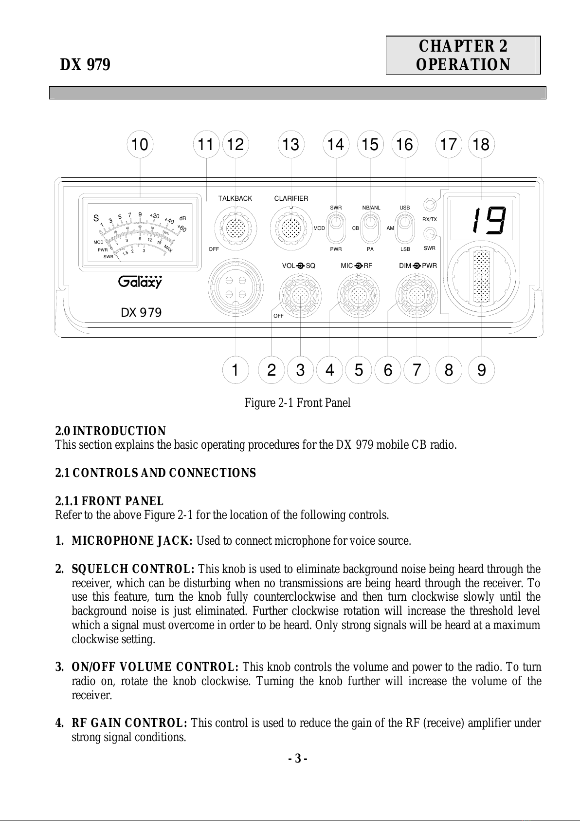
7. DIMMER CONTROL: This knob controls the level of brightness for the faceplate lettering, meter
lamp and channel display.
8. SWR LED: This LED lights red when your SWR is higher than about 3:1. This is not an exact
indicator of 3:1 SWR, but it is an indication that you should check your SWR reading.
9. CHANNEL SELECTOR: This control is used to select the desired transmit and receive channel.
10.FRONT PANEL METER: The front panel meter allows the user to monitor incoming signal
strength, RF output power, SWR level and AM modulation level.
11.ILLUMINATED FACE PLATE: All faceplate lettering will fully illuminate to allow the user
easy viewing at night. This unique, solid state, backlight is designed to maximize night vision while
minimizing eye fatigue. Therefore, it is ideal for switch and control recognition day or night.
12.TALKBACK CONTROL: Adjust this knob for desired volume of Talkback. This is used to
monitor your own voice. For example, you could use this feature to compare different microphones.
13.CLARIFIER CONTROL: Allows tuning of the receive frequency above or below the channel
frequency by up to 1.0KHz. Although this control is intended primarily to tune in SSB signals, it
may be used to optimize AM signals.
14.SWR/MOD/PWR SWITCH: This switch controls the function of the meter during the transmit
mode. In the “SWR” position, the meter indicates the Standing Wave Ratio (SWR) of your antenna.
There are no adjustments because the SWR circuit in this radio calibrates itself automatically. When
the switch is in the “MOD” position, the green scale on the meter indicates your percentage of
modulation in the AM mode only. They are most accurate when testing at maximum power output.
When this switch is in “PWR” position, the meter indicates your power output.
15.NB-ANL/CB/PA SWITCH: When the switch is in the NB/ANL position, the Noise Blanker (NB)
and Automatic Noise Limiter (ANL) circuits are activated. The Noise Blanker is very effective in
eliminating repetitive impulse noise such as ignition interference. In the CB position, the PA
function is disabled and the radio will transmit and receive on the speaker that is connected. In the
PA position, the radio acts as public address amplifier. Your voice will come out of the speaker that
is plugged into the PA. SP. jack on the rear panel. The radio does not operate when you are in the
PA mode.
16.MODE SWITCH: This control allows you to select one of the following operating modes:
AM/USB/LSB.
17.RX/TX LED: This LED is green during receive and red during transmit.
18.CHANNEL DISPLAY: The channel display indicates the current selected channel.
All manuals and user guides at all-guides.com

- 5 -
REAR PANEL
Figure 2-2 represents the location of the following connections:
Figure 2-2 Rear Panel
1. ANTENNA: This jack accepts a 50 ohm coaxial cable with a PL-259 type plug.
2. DC POWER: This jack accepts the 13.8V DC power cable with built-in fuse. The power cord
provided with the radio has a black and red wire. The black goes to negative and red goes to
positive.
3. PA SP: This jack is for PA operation. Before operating, you must first connect a PA speaker (8
ohms, 4W) to this jack.
4. EXT. SP: This jack accepts a 4 to 8 ohm, 5 watt external speaker. When the external speaker is
connected to this jack, the built-in speaker will be disabled.
5. F.C.: This jack is used to connect the optional Galaxy FC347 six-digit frequency counter. All
connections, including DC power, are provided to the FC347 through this jack.
MODEL NO. : DX 979
CB TRANSCEIVER
AM/SSB 40 CH
DATE OF MFG.:
FCC ID : MEE − DX − 979
SERIAL NO. :
1
ANT
2
- DC 13.8V +
EXT SP.
F.C.
PA SP.
3 45
This device complies with part 15 of the FCC Rules. Operation is subject
to the condition that this device does not cause harmful interference.
Service Manual at www.GalaxyRadios.com
All manuals and user guides at all-guides.com
all-guides.com

- 6 -
2.1.3 FREQUENCY CHART
CHANNEL
CHANNEL FREQUENCY
(MHz) CHANNEL
CHANNEL FREQUENCY
(MHz)
1 26.965 21 27.215
2 26.975 22 27.225
3 26.985 23 27.255
4 27.005 24 27.235
5 27.015 25 27.245
6 27.025 26 27.265
7 27.035 27 27.275
8 27.055 28 27.285
9 27.065 29 27.295
10 27.075 30 27.305
11 27.085 31 27.315
12 27.105 32 27.325
13 27.115 33 27.335
14 27.125 34 27.345
15 27.135 35 27.355
16 27.155 36 27.365
17 27.165 37 27.375
18 27.175 38 27.385
19 27.185 39 27.395
20 27.205 40 27.405
All manuals and user guides at all-guides.com

- 7 -
2.2 MICROPHONE
The receiver and transmitter are controlled by the push-to-talk switch on the microphone. Press the
switch and the transmitter is activated, release the switch to receive. When transmitting, hold the
microphone two inches from your mouth and speak clearly in a normal voice. The radio comes
complete with a low impedance (500 ohm) dynamic microphone.
2.3 OPERATION
2.3.1 PROCEDURE TO RECEIVE
1. Be sure that the power source, microphone and antenna are connected to the proper connectors
before going to the next step.
2. Press the POWER switch to apply power to the radio.
3. Set the VOL to a comfortable listening level.
4. Set the MODE switch to the desired mode.
5. Listen to the background noise from the speaker. Turn the SQUELCH knob slowly clockwise until
the noise just disappears. The SQUELCH is now properly adjusted. The receiver will remain quiet
until a signal is actually received. Do not advance the control too far or some of weaker signals will
not be heard.
6. Set the CHANNEL selector switch to the desired channel.
7. Set the RF GAIN control fully clockwise for maximum RF gain.
8. Adjust the CLARIFIER control to clarify the SSB signals or to optimize AM signals.
2.3.2 PROCEDURE TO TRANSMIT
1. Select the desired channel of transmission
2. Set the MIC GAIN control fully clockwise.
3. If the channel is clear, depress the push-to-talk switch on the microphone and speak in a normal
voice.
All manuals and user guides at all-guides.com

- 8 -
2.4 ALTERNATE MICROPHONES AND INSTALLATION
For best results, the user should select a low impedance dynamic type microphone or a transistorized
microphone. Transistorized type microphones have a low output impedance characteristic. The
microphones must be provided with a four-lead cable. The audio conductor and its shielded lead
comprise two of the leads. The third lead is for transmit control and the fourth is for receiving control.
The microphone should provide the functions shown in the schematic below (Figure 2-3).
4 WIRE MIC CABLE
Pin Number Mic Cable Lead
1 Audio Shield
2 Audio Lead
3 Transmit Control
4 Receive Control
Figure 2-3 Your Transceiver Microphone Schematic
Figure 2-4 Microphone plug and pin numbers viewed from rear of pin receptacle.
All manuals and user guides at all-guides.com

- 9 -
DX 979
CHAPTER 3
CIRCUIT
DESCRIPTION
3.0 INTRODUCTION
This section explains the technical theory of operation for the DX 979 mobile CB radio.
3.1 PLL CIRCUIT
The Phase Lock Loop (PLL) circuit is responsible for developing the receiver’s first local oscillator
signal and the transmitter’s exciter signal. The PLL circuit consists primarily of IC2, IC3, Q25, Q29
and Q28. The PLL circuit is programmed by the rotary channel switch GPS-668. The GPS-668
communicates the correct binary data information to the programmable divider inside of IC3. IC3 then
controls the VCO (Voltage Controlled Oscillator) to oscillate on the correct frequency. This signal is
fed either into the receiver’s first mixer (for receive operation) or the transmitter’s mixer (for transmit
operation).
3.2 RECEIVER CIRCUIT
The incoming RF signal comes into the radio via the antenna and into the front-end pre-amp, Q17. The
RF signal is fed into the mixer circuit of Q18/Q19 and then into the AM IF section of the receiver. The
signal is then detected by the AM detector and then fed to the audio amplifier section of the receiver
and finally out to the speaker.
3.3 TRANSMITTER MODULATION CIRCUIT
(1) The transmitter modulation circuit modulates the low-level RF signal from the PLL exciter circuit
with the user’s audio voice signal from the microphone. The audio from the microphone is then
amplified and fed into the transmit amplifier circuit.
(2) If the transceiver is in the AM mode, the AF power amplifier modulates the last RF amplifier,
which produces a true amplitude modulated RF signal.
(3) If the transceiver is in the SSB mode, the audio signal is mixed with the 10.6975MHz oscillator in
IC6.
3.4 TRANSMITTER AMPLIFIER CIRCUIT
The transmitter takes the basic exciter signal from IC9 of the TX mixer and amplifies it through a series
of amplifiers consisting of Q52, Q51, Q49 and Q47 where it is sent out to the antenna connector.
All manuals and user guides at all-guides.com

- 10 -
All manuals and user guides at all-guides.com
all-guides.com

- 11 -
DX 979
CHAPTER 4
ALIGNMENT
4.0 REQUIRED TEST EQUIPMENT
cDC Power Supply (13.8VDC, 10A)
dRF Wattmeter (10W)
eMulti-meter
fAutomatic Modulation Meter
gAudio Signal Generator
hFrequency Counter (100 MHz)
iRF Signal Generator (100 MHz)
jAutomatic Distortion Meter
kOscilloscope (50 MHz)
lSinad Meter
4.1 ALIGNMENT PROCEDURES
This transceiver has been aligned at the factory and does not require any adjustments at installation.
The required test equipment listed are used for the test setup or alignment shown in Figure 4-1
Transmitter Test Setup and Figure 4-2 Receiver Test Setup. These test setups are used in part or total
during the following adjustments. Refer to page 15 for adjustment locations.
4.1.1 PLL ALIGNMENT
ITEM U.U.T. SETTING
ADJUST
POINT MEASUREMENT
VCO Disconnect ‘short PCB’ from TP7, TP8 and TP9.
Set radio to CH 1 AM RX mode.
Connect Multi-meter to TP2.
L14
2.5 VDC ±0.1
Set CLARIFIER Control to 12 o’clock.
Connect Oscilloscope to TP3.
L15
Adjust for max.
Connect Frequency Counter to IC3 Pin 8. VC1 10.2400MHz ±20Hz
AM
Frequency Set radio to CH 19 AM RX mode.
Connect Frequency Counter to TP3.
L20
16.4900MHz ±20Hz
USB
Frequency Set radio to CH 19 USB RX mode.
Connect Frequency Counter to TP3.
L21
16.4925MHz ±20Hz
LSB
Frequency Set radio to CH 19 LSB RX mode.
Connect Frequency Counter to TP3.
L22
16.4875MHz ±20Hz
TX Offset
Frequency Set radio to CH 19 LSB TX mode.
Connect Frequency Counter to TP3.
VR7
16.4875MHz ±20Hz
AM OSC Set radio to CH 19 AM TX mode.
Connect Frequency Counter to TP5.
L23
10.6950MHz ±10Hz
USB OSC Set radio to CH 19 USB TX mode.
Connect Frequency Counter to TP5.
Set VR6 fully clockwise
L24 10.6925MHz ±10Hz
LSB OSC Set radio to CH 19 LSB TX mode.Connect
Frequency Counter to TP5.
Set VR6 back to mid position when finished.
L25 10.6975MHz ±10Hz
All manuals and user guides at all-guides.com

- 12 -
4.1.2 TRANSMITTER ALIGNMENT
ITEM U.U.T. SETTING
ADJUST
POINT MEASUREMENT
BIAS Current Set radio to CH 19 USB TX mode.
Modulation Off.
Remove “short PCB” from TP7, TP8, TP9.
Connect current meter to TP7(+) and TP9 (-)
Connect current meter to TP7(+) and TP8 (-)
VR12
VR10
50 mA
100 mA
SSB APC Set radio to CH 19 USB RX mode.
Connect Multi-meter to TP7. VR17 12.5 VDC
SSB TX Power Connect “short PCB” to TP7 and TP9.
Connect RF Power Meter to antenna jack.
Set radio to CH 19 USB TX mode.
AF signal 30mV, 1 KHz to microphone.
Set RF PWR fully clockwise.
Set MIC GAIN fully clockwise.
L40,L42,
L43,L44 MAX > 12W
Spurious Emission
Minimum.
Balance Power
Between CH1 and
CH40.
SSB ALC
Set radio to CH 19 USB TX mode.
AF signal 30mV, 1 KHz to microphone.
VR13
11.5 W
SSB Carrier
Balance Set radio to CH 19 USB TX mode.
Set MIC GAIN fully counter-clockwise.
Connect Oscilloscope to antenna connector.
VR6
Spurious Emission to
Minimum.
AM TX
High Power Set radio to CH 19 AM TX mode.
Modulation Off.
Set RF POWER fully clockwise.
VR14
3.8 W
AM TX
Low Power Set RF POWER fully counterclockwise.
VR18 0.3W±0.2W
RF Power
Meter Set radio to CH 19 AM TX mode.
Set RF POWER fully clockwise.
Set SWR/MOD/PWR Switch to PWR
position.
VR9
For a needle reading
of “4” on TX PWR
scale.
AM Modulation
Set radio to CH 19 AM TX mode.
AF signal 30mV, 1 KHz to microphone.
Set MIC Gain fully clockwise.
Set SWR/MOD/PWR Switch to MOD position
VR16
For a needle reading
of 95% on the
external modulation
meter.
AM Modulation
Meter Set radio to CH 19 AM TX mode.
AF signal 30mV, 1 KHz to microphone.
Set MIC Gain fully clockwise.
VR15 For a needle reading
of 95% on the
modulation scale.
All manuals and user guides at all-guides.com

- 13 -
4.1.3 RECEIVER ALIGNMENT
ITEM U.U.T. SETTING
ADJUST
POINT MEASUREMENT
AM Sensitivity Set radio to CH 19 AM RX mode.
Set RF GAIN Fully Clockwise.
Set SQ Fully Counter Clockwise.
Set VOL Control at 2 o’clock.
Set NB/ANL switch to OFF position.
Set CLARIFIER Control to 12 o’clock.
Connect RF SG to antenna jack
Frequency 27.185 MHz, 1uV. Mod 30%.
L2,L3,L5,L6,
L7,L8,L9,L10
Audio Output > 2V
S/N > 10 dB.
Set radio to CH 40 AM RX mode.
RF SG setting 27.405 MHz.
Set radio to CH 1 AM RX mode.
RF SG setting 26.965 MHz.
L5,L6
For Balance Between
CH 1 and CH 40.
USB Sensitivity Set radio to CH19 USB RX mode.
Set VOL Control Fully Clockwise.
RF SG setting 27.186 MHz, 0.5uV. Mod off.
L11,L12
Audio Output >2V
S/N > 10dB.
LSB Sensitivity Set radio to CH19 LSB RX mode.
Set VOL Control Fully Clockwise.
RF SG setting 27.184 MHz, 0.5uV. Mod off.
L11,L12
Audio Output >2V
S/N >10dB.
NB Adjust Set radio to CH 18 AM RX mode
RF SG setting 27.185 MHz, 1000uV. Mod off.
Set NB/OFF switch to ON position.
Connect Multi-meter to TP1 (D2 cathode).
L1
DC Voltage to max.
( > 2.0V )
AM Squelch Set radio to CH 19 AM RX mode.
Set SQ Control Fully Clockwise.
RF SG setting 27.185 MHz, 20mV. Mod 30%.
VR4 Adjust very slowly
until squelch just
closes.
SSB Squelch Set radio to CH 19 USB RX mode.
Set SQ Control Fully Clockwise.
RF SG setting 27.186 MHz, 20 mV. Mod off.
VR3 Adjust very slowly
until squelch just
closes
AM S-Meter Set radio to CH 19 AM RX mode.
RF SG setting 27.185 MHz, 100uV. Mod 30%.
VR1 For a reading of “9”
on the “S” scale.
SSB S-Meter
Set radio to CH 19 USB RX mode.
RF SG setting 27.186 MHz, 100uV. Mod off.
VR2
For a reading of “9”
on the “S” scale
All manuals and user guides at all-guides.com

- 14 -
Figure 4-1 Transmitter test setup
Figure 4-2 Receiver test setup
All manuals and user guides at all-guides.com

- 15 -
DX979 MAIN PCB ADJUSTMENT LOCATION
DRIVER
BIAS FINAL
BIAS RF METER ALC
AM
MOD
AM LOW POWER
APC
AM HI POWER
AM MOD METER
SSB S-METER
AM S-METER
SSB SQUELCH
AM SQUELCH
TX OFFSET
CARRIER
BALANCE
10.240 MHz
ADJUST
A
M LOW POWER
AM
MOD
A
M
SSB
All manuals and user guides at all-guides.com
all-guides.com

- 16 -
DX 979
CHAPTER 5
MAINTENANCE
5.0 PRECAUTIONS
The inherent quality of the solid-state components used in this transceiver will provide many years of
continuous use. Taking the following precautions will prevent damage to the transceiver.
(i) Never key the transmitter unless an antenna or suitable dummy load is connected to the antenna
receptacle.
(ii) Ensure that the input voltage does not exceed 16 VDC or fall below 11.
(iii) Transmitting over long periods can cause heat built-up and cause transmitter damage.
5.1 PERIODIC INSPECTION
This unit is aligned at the factory to deliver maximum performance. However, continued performance
cannot be expected without periodic inspection and maintenance. Important points to be checked
regularly are as follows;
Check Item Action
Whip antenna
(option) If cracked or broken, replace it.
Coaxial cable If sheath is cracked or immersed
in water, install new coaxial
cable.
Coaxial & power
plug connections If loosened, reconnect. If
corroded, clean contacts.
Battery connection If corroded, clean power
terminals.
Ground terminal If corroded, clean terminal.
5.2 FUSE REPLACEMENT
To protect the equipment from serious damage, a fuse is provided on the power supply lines. The fuse
protects against over voltage / reverse polarity or internal fault of the equipment. If the fuse has blown,
first find out the cause of the trouble before replacing it. A fuse rated for more than the transceiver
requirement should not be used, since it may permanently damage the equipment. Damage due to over
fusing is not covered by the warranty.
All manuals and user guides at all-guides.com

- 17 -
DX 979
CHAPTER 6
DIAGRAMS &
PARTS LIST
6.0 GENERAL
Information on most electrical and mechanical parts is included in the parts list. The reference
designators are in alphanumeric order.
All manuals and user guides at all-guides.com

- 18 -
DX 979 ROTARY SWITCH PCB (EPT092920Z)
(SMD-COPPER SIDE) ( COMPONENT SIDE )
All manuals and user guides at all-guides.com

- 19 -
PART LIST:
DX 979 ROTARY SW. P.C.B
ITEM REFERENCE
NUMBER RANGER PART
NUMBER DESCRIPTION
1 EPT092920Z ROTARY SW PCB
2 R207,R210,R218 RCY010004Z CHIP/F/R 0.0 Ω0.1W
3 R201 RCY013314Z CHIP/F/R 330 Ω0.1W
4 R202,R203,R204,R205,
R206 RCY016814Z CHIP/F/R 680 Ω0.1W
5 R215 RCY014724Z CHIP/F/R 4.7K Ω0.1W
6 R221 RCY016824Z CHIP/F/R 6.8K Ω0.1W
7 R214 RCY012234Z CHIP/F/R 22K Ω0.1W
8 R220 RCY016834Z CHIP/F/R 68K Ω0.1W
9 C201,C202 CK1104AB5X CHIP/C 0.1uF 50WV
10
D201,D202,D203,D204,
D205,D206,D207,D208,
D209,D210,D211,D212,
D13,D214,D215,D216,D
217,D218,D219,D220,D
226,D227,D228
EDSS00355Y DIODE (S.M.D.) 1SS355
11 D221,D222,D223,D224,
D225 EDSS00181Y DIODE (S.M.D.) 1SS181-TE85L
12 Q207 TY2SC2712G TR 2SC2712GR-TE85L
13 Q201,Q202,Q203,Q204,
Q206 TYZRN1403Z TR RN1403-TE85L
14 Q205 TYZRN2403Z TR RN2403-TE85L
15 J201,J206 EX07N48223 PCB CONN/S 2 PIN
16 J203 EX07N48350 PCB CONN/S 3 PIN
17 J202 EX07N48222 PCB CONN/S 5 PIN
18 J204 EX07N48209 PCB CONN/S 10 PIN
19 ROTARY SW EWRT32059S ROTARY SW GPS-0668
20 J205 WX01070710 JUMPER WIRE
All manuals and user guides at all-guides.com
Other manuals for DX 979
2
Table of contents
Other Galaxy Radio manuals