Esu ECoSDetector User manual

Instruction manual
1. Edition, June 2011
P/N 03811-10659
50094 ECoSDetector
50096 ECoSDetector Standard
ECoSDetector

2
1. EG - Declaration of conformity ............................... 3
2. WEEE-Declaration .................................................... 3
3. Important Notes – Please read first........................ 3
3.1. Scope of delivery...........................................................3
4. Occupancy detection and its function.................... 4
4.1. Contact with the common conductor ...........................4
4.2. Current sensors (not with ECoSDetector Standard) .......4
4.3. RailCom® feedback (not with ECoSDetector Standard).4
5. General properties................................................... 5
5.1. Properties of the ECoSDetector Standard......................5
5.2. Properties of the ECoSDetector.....................................5
6. Connecting it to the tracks...................................... 6
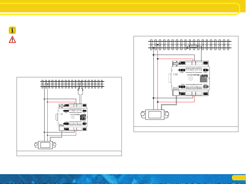
6.1. Common contacts ........................................................6
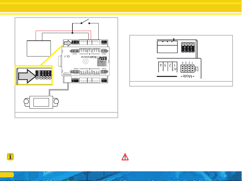
6.1.1. Jumpers .....................................................................6
6.1.2. 3-rail track system (contact track section)...................6
6.1.3. Track switches............................................................7
6.1.4. Reed contacts ............................................................7
6.1.5. Externally supplied switches .......................................7
6.2. Current sensor (not for ECoSDetector Standard) ...........8
6.2.1. Jumpers .....................................................................8
6.2.2. 2-rail track system......................................................8
6.2.3. 3-rail track system......................................................9
6.3. RailCom® feedback (no for ECoSDetector Standard) ....9
6.4. Two booster sectors on one ECoSDetector..................10
7. Connecting to the command station.................... 10
8. Configuration on the command station .............. 11
8.1. Name and indenture number......................................11
8.2. Feedback status ..........................................................12
Content
8.3. Finding an ECoSDetector ............................................12
8.4. Administration of several ECoSDetectors.....................12
9. Utilising feedback information............................. 13
9.1. Setting routes .............................................................13
9.2. Track control diagram .................................................13
10. Technical data....................................................... 14
10.1. Technical data ECoSDetector.....................................14
10.2. Technical data ECoSDetector Standard......................14
11. Support and Assistance....................................... 14
12. Warranty Certificate ............................................ 15
Copyright 1998 - 2012 by ESU electronic solutions ulm GmbH & Co KG. Mis-
takes, changes resulting in technical advancement, availability and all other rights
reserved. Electrical and mechanical characteristics, dimensions and sketches are
subject to change without prior notice. ESU may not be held responsible for any
damage or consequential loss or damage caused by inappropriate use of the pro-
duct, abnormal operating conditions, unauthorised modifications to the product,
etc. Not suitable for children under 14 years of age. Inappropriate use may result
in injury due to sharp points and edges.
Märklin® is a registered trademark of Gebr. Märklin® und Cie. GmbH, Göppin-
gen, Germany. RailCom® is a registered trademark of Lenz Elektronik GmbH,
Giessen. RailComPlus® is a registered trademark of Lenz Elektronik GmbH, Gies-
sen. All other trademarks are the property of their respective legal owners.
According to its policy ESU electronic solutions ulm GmbH & Co KG continues to
develop its products. Therefore ESU reserves the right to implement changes and
improvements to any of the products listed in the ESU documentation.
Duplication and preproduction of this documentation in any shape or form requi-
res prior written consent from ESU.

3
1. EG - Declaration of conformity
We, ESU electronic solutions ulm GmbH & Co. KG, Edisonallee
29, D-89231 Neu-Ulm, Germany, declare in sole responsibility that
the product
Product description: ECoSDetector
Part number: 50094, 50096
complies with all relevant regulations of the Directive for Electro-
magnetic Compatibility (2004/108/EG). The following harmonised
standards have been applied:
EN 55014-1:2006 + A1:2009: Electromagnetic Compatibility -
requirements for household appliances, electric tools, and similar
apparatus - Part 1: Emission - Product
EN 55014-2:1997 + A1:2001 + A2:2008: Electromagnetic Compa-
tibility - Requirements for household appliances, electric tools, and
similar apparatus - Part 2: Immunity - Product family standard.
2. WEEE-Declaration
Disposal of obsolete electrical and electronic equipment (as prac-
tised in the European Union and other European countries with
dedicated collection systems).
This mark on the product, the packaging or the
relevant documentation indicates that this product
must not be treated like household waste. Instead
this product should be disposed of at a suitable
collection point for recycling of electrical and elec-
tronic appliances. Thus you contribute to avoid
negative impact on the environment and people’s health that
could be caused by inappropriate disposal. Recycling of materials
contributes to preserve our natural resources. For more informa-
tion regarding recycling of this product, please contact your local
authority, your waste collection service or the dealer / shop where
you purchased this product.
3. Important Notes – Please read first
We congratulate you to your purchase of an ESU ECoSDetector
feedback module. This manual provides step by step information
on the various options of use of this device. Therefore we have
one request:
Please read this manual carefully prior to commissioning. Alt-
hough the circuit board is quite robust incorrect wiring could lead
to damage or destruction of the module. If in doubt, please refrain
from any “expensive” experiments.
•The ECoSDetector is solely intended for use on electric model
train layouts. It may only be operated with the components de-
scribed in this manual. Any other use as described in this manual
is not permitted.
•All electrical work such as wiring the module may only be car-
ried out when power is turned off.
•Avoid any impact load or pressure against the module.
•Keep away from wet conditions or humidity.
•The circuit board may not get into contact with any metal ob-
jects or electrical conductors. This is particularly true for the
track signal.
•Never let your trains run unattended.
3.1. Scope of delivery
Please check if the following parts are in the packaging of your
ECoSDetector:
1x ECoSDetector respectively ECoSDetector Standard
1x Accessory bag (with 4 nos. 4-way terminal blocks, 2 nos. 2-way
terminal blocks)
1x ECoSlink connecting cable
1x Manual (which you are reading right now)
Important notes

4
4. Occupancy detection and its function
Occupancy detection systems are required in order to provide
information regarding the track status. A track can either be oc-
cupied or unoccupied.
This information is useful for parts of your layout that you cannot
directly see from your position (e.g.: storage yards) or if you wish
to display the track status on your track control diagram.
Occupancy feedback is an essential prerequisite for any partial or
fully automatic operation: the automated system respectively the
computer needs information in order to decide if a certain train
may enter a certain track or which route should be switched.
Furthermore modern occupancy detection systems can provide in-
formation about which vehicle is located in a certain track sector.
Subject to the track system and the application there are three
methods of how track occupancy can be determined.
4.1. Contact with the common conductor
The simplest form of feedback is to use reed contacts closing the
circuit to the common conductor, light barriers or photo sensors,
track contacts or track sections with integral switch contacts. With
the three-rail-system the occupancy detection is often realised by
insulating one outer track from the rest of the layout and thus use
it as an electrical switch. This corresponds with the well known
original “s88 configuration”. The ECoSDetector as well as the
ECoSDetector Standard support this mode.
4.2. Current sensors (not with ECoSDetector Standard)
With this method suitable for all track systems the detector mea-
sures the current flowing through the respective track sector. Every
electric load on the track causes a current flow. “A current flow” is
therefore equivalent to the “occupied” status of the track. There-
fore the status “there is no current flowing” means the track is
unoccupied.
All loads must draw a minimum current of about 1mA (0,001A)
in order to assure reliable operation of this current measuring
system.
Occupancy detection and its function
Commercially available resistor axles with about 18 kOhm can
just be detected provided the tracks are clean and the wheels sit
properly on the tracks. We recommend equipping two axles per
car with resistors. The resulting resistance value of about 9 kOhm
is reliably detected.
In case of an interruption of the track voltage (e.g.: due to a short
circuit or an emergency stop with power out) there will be no
current flow and occupancy detection is not possible any longer.
In order to prevent any incorrect “unoccupied” feedback to the
command station the occupancy status is frozen for the duration
of the power failure.
As soon as the track voltage is turned on again the occupancy
status is monitored and current information is transmitted to the
command station.
4.3. RailCom® feedback (not with ECoSDetector Standard)
Decoders equipped with RailCom® or RailComPlus® can provide
the locomotive number to the ECoSDetector which in turn will
transmit it to the command station. Finally we can determine pre-
cisely which locomotive is located on which track. The ECoSDetec-
tor must read the current flow in the track sector in order to read
out the RailCom feedback.

5
5. General properties
ECoSDetector feedback modules are suitable for operation with
the ESU command stations ECoS 50000, ECOS 50200 as well as
with the Central Station 60212 “Reloaded” with ESU Update.
The command station must have firmware version 3.4.1 or high-
er in order to be able to operate the ECoSDetector modules.
ECoSDetector modules detect track occupancy and transmit these
to the ECoSlink terminal of the command station. The “occupied”
information can either be displayed on the track control diagram,
for activating routes or to pass it on to a computer via the appro-
priate interface.
All ECoSDetector modules are automatically recognised by the
command station and integrated into the system. They can be
wired in any sequence can be adapted to your layout. The ECoS-
Detector is fully updateable. New firmware files are automatically
downloaded from the ECoS command station if a newer version
has become available.
The ECoSDetector occupancy detector can monitor up to 16 track
sectors. Internally they are subdivided into two groups of 8 each
that can be wired to one or two booster sectors. All feedback
inputs are galvanically separated from the track voltage by means
of optoelectronic couplers. This practically avoids any risk of short
circuits while the feedback functions very reliably.
The monitored track sectors are polled cyclically by a 32 Bit micro
controller thus avoiding any noticeable delays of the status feed-
back. In order to avoid any wrong occupancy feedback all sectors
act with a certain delay. This works as follows:
•Switch-on delay: Is a track occupancy detected it must remain on
for at least 4 milliseconds before this signal is considered valid and
before it is transmitted.
•Switch-off delay: If a previously occupied track is detected as
unoccupied the signal is only transmitted after a delay of 200 mil-
liseconds. Should this track sector during this delay period be re-
General properties
ported as “occupied” once again, there will be no feedback signal
and the switch-off delay starts again. Once the track is confirmed
as “unoccupied” and the switch-off delay period has passed the
“unoccupied” status will be reported to the command station.
Short interruptions - perhaps caused by poor contact between the
wheels and the track - can easily be filtered with this method.
ECoSDetector modules can be operated in parallel to s88 feed-
back modules at your command station.
5.1. Properties of the ECoSDetector Standard
The ECoSDetector Standard has 16 feedback inputs that work as
„common“contacts. An ECoSDetector Standard has to be wired
exactly in the same manner as an s88 module and can fully replace
it. Due to the robust ECoSlink feedback bus the feedback is far
more reliable.
The ECoSDetector Standard is mainly designed for 3-rail layouts or
for layouts with reed contacts.
5.2. Properties of the ECoSDetector
The ECoSDetector has 16 feedback inputs. Each of them can be
configured either as a “common” contact or as a current sensor
by means of a jumper. In addition, four of the 16 feedback inputs
are suitable for RailCom® feedback. If the inputs are configured
as current sensors the maximum permitted current is 3 A per track
sector.
Due to its flexibility the ECoSDetector is suitable for both 3-rail and
2-rail operation and for all model train gauges.

6
6. Connecting it to the tracks
In this paragraph we show you how to wire the ECoSDetector
module to the tracks. In the figures the ECoSDetector module is
shown; wiring the ECoSDetector Standard is identical. However,
on the ECoSDetector Standard there are no jumpers.
6.1. Common contacts
As feedback inputs configured as common inputs you may con-
nect all contacts that switch the input to the common conductor
(often this is the “brown“digital feeder). Thus you can switch eit-
her against the terminal marked as “0” or against the terminal 0
(brown) at the track.
6.1.1. Jumpers
The ECoSDetector has a jumper for each feedback input for confi-
guring the input either as common contact or as current sensor.
6.1.2. 3-rail track system (contact track section)
Figure 2 shows how to wire a contact track in a 3-rail system.
•Wire the inputs „0“and „B“of the ECoSDetector with the approp-
riate booster output. In example 2 both feedback groups “A” and
“B” are supplied from the same booster. Therefore the terminals
“0” and “B” on both sides of the ECoSDetector must be connec-
ted with each other. If you use a separate booster for the inputs of
group “B” (feedback inputs 9 through 16) the ECoSDetector has
to be wired as described in chapter 6.4.
•Connect the insulated sector of the track to be monitored to one
of the input terminals “1” to “16” of the ECoSDetector module.
Figure 1: „Jumpers“
Connecting it to the tracks
Figure 2: 3-rail track system as contact track
B
0
5678
If you wish to use the input as common contact place the corres-
ponding jumper to the outer position “3L”. In figure 1 all inputs
are configured as common contacts. But, of course, you may con-
figure each input individually.

7
The occupancy feedback will work trouble free if the track sector
to be monitored has been isolated at both ends.
Do not forget to set the jumpers of the ECoSDetector correctly.
This is not necessary with the ECoSDetector Standard.
Please keep the wiring between the feedback module and the
track sector to be monitored as short as possible. If the wires
are very long and installed close to each other it may result in an
unintentional data transfer between the wires. Even though only
one track sector is occupied several feedback inputs may report
“occupied”.
6.1.3. Track switches
Figure 3 shows how to connect a Märklin® track switch. Please
note that this track switch functions directionally!
Connecting it to the tracks
Figure 3: How to connect a track switch
B
0
5678
Connecting it to the tracks
6.1.4. Reed contacts
Figure 4 shows how to wire a reed contact. Please make sure that
you install sufficiently strong magnets at the underside of your
vehicles to assure reliable function even at high speeds!
6.1.5. Externally supplied switches
The ECoSDetector also works without direct connection to the
track by means of commercially available switches or push but-
tons. In this case you must supply the ECoSDetector with a DC
voltage (!) ranging between 12V and 22V. Figure 5 shows how
it is done:
B
0
5678
Figure 4: Connection of a reed contact to an outer conductor

8
Connecting it to the tracks
Please note that the jumper for the power supply (marked with an
arrow in figure 5 at the top left) must be set to the outer position
for this operating mode.
6.2. Current sensor (not for ECoSDetector Standard)
Each of the 16 feedback inputs of the ECoSDetector can be confi-
gured as current sensor. This is the most reliable type of feedback
and is suitable both for 3-rail systems and 2-rail systems.
If you have a choice (whenever you rewire your layout), select the
current sensor option since the feedback function is far more reli-
able than the known common contacts.
6.2.1. Jumpers
The ECoSDetector has a jumper for each feedback input in order
to configure this input either as common contact or as current
sensor.
If you wish to use an input as current sensor place the jumper
onto the inner position “2L”. In figure 6 the inputs 1 to 4 are
configured as current sensors. But, of course, you can configure
each input individually.
6.2.2. 2-rail track system
•Connect the inputs “0” and “B” of the ECoSDetector with the ap-
propriate booster output. In the example in figure 7 both feedback
groups “A” and “B” are supplied by the same booster. Therefore
the terminals “0” and “B” on both sides of the ECoSDetector
must be connected with each other. If you use a separate ECoS-
Boost for group “B” (feedback inputs 9 through 16) then the mo-
dule must be wired as described in chapter 6.4.
•Connect the feedback terminals “1” through “16” with the cor-
responding track sector which must be insulated from the rest of
the layout at both ends (!).
Please make sure that you always cut the “correct” track and thus
the correct pole of the digital track voltage when isolating the track
sectors. In figure 7 it is shown that the conductor “B” (red) must be
isolated. This must be done in the same way for the entire layout.
Figure 6: „Jumpers“
DC
12-22Volt
+-
5678
Figure 5: Operation with common rocker switches
DC
12-22Volt
+-
5678

9
Connecting it to the tracks Connecting it to the tracks
Otherwise a short circuit would occur every time a locomotive or
car bridges the gap between different sectors.
6.2.3. 3-rail track system
The current sensor mode is also recommended for the 3-rail track
system. Cut the centre conductor of the track sector to be moni-
tored at both (!) ends and connect it to the feedback input of the
ECoSDetector.
•Connect the inputs „0“and „B“of the ECoSDetector with the ap-
propriate booster output. In the example shown in figure 8 both
feedback groups “A” and “B” are supplied by the same booster.
Therefore the terminals “0” and “B” on both sides of the ECoS-
Detector must be connected with each other. If you use a separate
ECoSBoost for group “B” (feedback inputs 9 through 16) then the
module must be wired as described in chapter 6.4.
•Connect the feedback terminals “1” through “16” with the cor-
responding track sector (isolated centre conductor) which must be
insulated from the rest of the layout at both ends (!).
Figure 8: 3-rail track system current sensor
B0
RailCom
RailCom
5678
5678
B0
RailCom
RailCom
Figure 7: 2-rail track system current sensor
6.3. RailCom® feedback (no for ECoSDetector Standard)
In addition to the conventional occupancy feedback (“track occu-
pied” or “track unoccupied”) the inputs 1, 5, 9 and 13 can read
out the address of the locomotive locate on this particular track
sector. A pre-condition for this mode is that the locomotive deco-
der supports RailCom® or RailComPlus® and that this function is
also activated in the decoder. Only then the locomotive decoder

10
will transmit its address continuously and thus enables the ECoS-
Detector to receive it and to transmit it to the command station. In
order to enable the RailCom® feedback configure the correspon-
ding output as described in chapter 6.4 to current sensor mode
and make sure that all ESU decoders have the latest firmware.
If the feedback input is configured as common contact the Rail-
Com® feedback cannot work.
6.4. Two booster sectors on one ECoSDetector
The feedback inputs of the ECoSDetector are divided into two
groups: “A” (inputs 1 through 8) and “B” (inputs 9 through16).
These two groups can be supplied by two different booster sec-
tors. Each feedback group has terminals “B” and “0” to be con-
nected to the booster outputs that supplies power for the track
sector to be monitored. In figure 9 we show an example of how
to wire a 3-rail system where both feedback groups receive power
from their own separate power supply (group “A” form the ECoS
and group “B” from a separate ECoSBoost.
Connecting to the command station
7. Connecting to the command station
The ECoSDetector is wired with the supplied ECoSlink cable direct-
ly to one of the three ECoSlink sockets of your ECoS. The power
supply for each ECoSDetector is provided by the ECoS command
station. To which socket you connect which ECoSDetector has no
relevance regarding the internal numbering sequence of the feed-
back inputs. After connecting it each ECoSDetector is automati-
cally detected by the command station and linked to the system.
To be able to utilize the feedback inputs successfully you only have
to set a few things in the setup menu on the command station.
If you wish to use more than three ECoSDetector modules or if
the supplied cable is too short you should extend the ECoSlink bus
with the aid of the ECoSlink-Terminal (ESU part number 50099).
The bus can be extended up to 100 meters. Due to the bus topo-
logy an extension of the supplied ECoSlink cable is not possible!
After connecting the ECoSDetector successfully the status LED a)
must be lit continuously. The button b) can be used for easy iden-
tification of the ECoSDetector module.
B
0
B0
ECoS ECoSBoost
5678
Figure 9: 3-rail layout with two booster sections Figure 10: LED a) and button b)
a)
b)

11
Connecting to the command station Configuration on the command station
8. Configuration on the command station
After connecting the ECoSDetector to the command station the
module is automatically detected and linked to the system.
Please make sure that your ECoS has firmware 3.4.1 or higher.
Otherwise the ECoSDetector is not recognised.
The configuration takes place on the command station. Each
ECoSDetector is displayed with its name in a list called “ECoSlink
devices”.
In figure 11 the “ECoSDetector” is displayed by its name. This is
the factory default value and should be changed by you as soon as
you have more than one ECoSDetector module.
If you wish to use more than one ECoSDetector module it is best
to connect them one after another. This practically eliminates the
possibility of confusing the modules during configuration.
8.1. Name and indenture number
Select the first ECoSDetector from the list as shown in figure 11
and press “Edit”. A configuration dialogue opens for this ECoS-
Detector module.
ECoSDetector Name: Assign a distinct name for each module,
e.g.: “Main Station” or “Storage Yard” to assure that you al-
ways know its function respectively the part of your layout that
is monitored by it.
ECoSDetector Number: In order to enable operation of the
ECoSDetector parallel to the known s88 feedback modules each
ECoSDetector must have a “number” similar to the s88 modu-
les. In this manner it is easily possible to differentiate between
the individual modules. The number can be any number bet-
ween 1 and 100. When using several ECoSDetector modules it is
not absolutely necessary to use continuous numbers. There may
be gaps in your numbering sequence.
Figure 11: ECoS Setup: Geräte im System
Figure 12: ECoSDetector Konfiguration

12
8.2. Feedback status
For testing purposes it is often helpful to indicate the actual occu-
pancy status by a visual display. This is possible in the configuration
menu. The status “occupied” is indicated for each feedback input
by “filled square” on the touch panel of the command station.
8.3. Finding an ECoSDetector
After pressing the screen button “Blinking” in the configuration
dialogue (also refer to figure 12) the LED of the ECoSDetector
starts blinking rhythmically. This makes it far easier for you to find
the module.
Alternately you can press the button on the ECoSDetector at any
time. A dialogue window will open on the ECoS screen that dis-
play both name and indenture number of the module.
8.4. Administration of several ECoSDetectors
When your layout grows and you wish to use several ECoSDetec-
tor modules it may become necessary to change the indenture
numbers at a later stage. We have developed a comfortable me-
thod for this.
•Press the tab “Administration” of any ECoSDetector in the confi-
guration menu. A window similar to that in figure 14 will open.
The list displays all detected ECoSDetector modules with their
names and indenture numbers. The list is sorted by indenture
number.
If you now wish to assign a new indenture number to an ECoS-
Detector simply mark the module concerned and press the button
«N+» in order to increase the number or press «N-» in order to
decrease the number.
Please make sure that all modules have different numbers.
Figure 13: Find the ECoSDetector
Figure 14: Administration of several ECoSDetector modules
Configuration on the command station

13
9. Utilising feedback information
The feedback information provided by the ECoSDetector can be
used exactly as described in chapter 15 of the ECoS manual. Of
course, now the choice is not limited to s88 modules but also
offers ECoSDetector feedback contacts.
9.1. Setting routes
If you wish to set a route you can now also select the ECoSDetec-
tor modules from the list of the feedback modules. Please note
that the modules are sorted by increasing indenture number.
Utilising feedback information
Figure 15: Select a module
Figure 16: Display of loco address in the track control diagram
9.2. Track control diagram
You can display locomotive numbers read out with RailCom® on
the track control diagram. For this purpose a new icon has been
introduced in the setup of the track control diagram. After pres-
sing the button shown on the left you can locate a display module
that displays both the locomotive address and its name as soon as
a valid address has been detected in this track sector.
If you touch the display field either on the left or right side the
locomotive is automatically assigned to the corresponding throttle
of the ECoS and the display automatically changes to the train
control mode

14
10. Technical data
10.1. Technical data ECoSDetector
Technical data ECoSDetector
Operating modes Direct bus connection to ECoSlink. Operation with ECoS
or Central Station «Reloaded» possible.
Feedback
16 feedback inputs. Configurable via jumpers as digital
inputs (e.g.: for track switches or reed contacts) or as oc-
cupancy detector (current sensor).
Galvanic separation of the feedback inputs from the com-
mand station.
Maximum current 3A per feedback input.
RailCom®
4 of the 16 feedback inputs are configurable as RailCom
feedback inputs («local detector»). Detection of the lo-
comotive address.
Dimensions 86mm x 86mm x 25mm
Scope of delivery feedback module, terminals, ECoSlink bus cable, detailed
manual
10.2. Technical data ECoSDetector Standard
Technical data ECoSDetector Standard
Operating modes Direct bus connection to ECoSlink. Operation with ECoS
or Central Station «Reloaded» possible.
Feedback
16 feedback inputs as digital inputs (e.g.: for track swit-
ches or reed contacts).
Galvanic separation of the feedback inputs from the com-
mand station
Dimensions 86mm x 86mm x 25mm
Scope of delivery ECoSDetector Standard feedback module, terminals,
ECoSlink bus cable, detailed manual
Technical data
11. Support and Assistance
Your model train dealer or hobby shop is your competent partner
for all questions regarding your LokPilot decoder. In fact he is your
competent partner for all questions around model trains.
There are many ways to get in touch with us. For enquiries please
use either email, fax (please provide your fax-no. or email address)
or go to www.esu.eu/en/forum and we will reply within a few
days.
Please call our hotline only in case of complex enquiries that can’t
be dealt with by email or fax. The hotline is often very busy and
you may encounter delays. Rather send an email or fax and also
check our website for more information. You will find many hints
under “Support / FAQ” and even feedback from other users that
may help you with your particular question.
Of course we will always assist you; please contact us at:
USA & Canada (English support), please contact:
Phone: +1 (570) 649-5048
Tuesday & Thursday 9:00am - 3:00pm (CT)
Fax: +1 (866) 591-6440
Email: [email protected]
Mail: ESU LLC
477 Knopp Drive
US-PA-17756 Muncy
Germany and all other countries, please contact:
Fax: ++49 (0) 731 - 1 84 78 - 299
Email: www.esu.eu/en/forum
Mail: ESU GmbH & Co. KG
- Technical support -
Edisonallee 29
D-89231 Neu-Ulm
www.esu.eu

15
12. Warranty Certificate
24 Months warranty form date of purchase
Dear customer,
Congratulations on purchasing this ESU product. This quality product was manufactured applying the most advanced production methods
and processes and was subject to stringent quality checks and tests.
Therefore ESU electronic solutions ulm GmbH & Co. KG grants you a warranty for the purchase of ESU products that far exceeds the national
warranty as governed by legislation in your country and beyond the warranty from your authorised ESU dealer.
ESU grants an extended manufacturer’s warranty of 24 months from date of purchase.
Warranty conditions:
•This warranty is valid for all ESU products that have been purchased from an authorised ESU dealer.
•Any service, repair or replacement under this warranty requires proof of purchase. The filled in warranty certificate together with the receipt
from your ESU dealer serves as proof of purchase. We recommend keeping the warranty certificate together with the receipt.
•In case of a claim please fill in the enclosed failure report card as detailed and precise as possible and return it with your faulty product.
•Please use the appropriate postage when shipping to ESU.
Extent of warranty / exclusions:
This warranty covers the repair or replacement free of charge at the discretion of ESU electronic solutions ulm GmbH & Co. KG of any faulty
parts that are caused by design faults or faults in production, material or transport. Any further claims are explicitly excluded.
The warranty expires:
1. In case of wear and tear due to normal use.
2. In case of conversions of ESU – products with parts not approved by the manufacturer.
3. In case of modification of parts.
4. In case of inappropriate use (different to the intended use as specified by the manufacturer).
5. If the instructions as laid down in the user manual by ESU electronic solutions ulm GmbH & Co. KG were not adhered to.
There is no extension of the warranty period due to any repairs carried out by ESU or re-placements.
You may submit your warranty claim either with your dealer or by shipping the product in question with the warranty certificate, the receipt
of purchase and the fault description directly to ESU electronic solutions ulm GmbH & Co. KG at:
ESU GmbH & Co. KG
- Service department -
Edisonallee 29
D-89231 Neu-Ulm
GERMANY
Warranty Certificate

16
1. Customer data (Please write in block letters)
Name:...................
Street:...................
ZIP/City: ................ ||||||
Country: ...............
Email:....................
Phone: ..................
Date:.....................
Signature: .............
2. Error class
Is not detected by the command station (LED flashes) No feedback information
No function (error cannot be exactly determined) No RailCom® address information
3. Error description (use extra page, if needed)
4. Receipt / Proof of purchase
Please enclose your receipt / invoice. Otherwise no warranty possible!
5. Additional information: 6. Your retailer:
Retailer´s stamp or address
Trouble shooting sheet
This manual suits for next models
3
Table of contents
Popular Network Hardware manuals by other brands

Watlow Electric
Watlow Electric 945 Series How to use

Juniper
Juniper NetScreen-IDP 3.0 quick start guide

ADC
ADC Cross-Connect Family FlexDSX Specification sheet

BroadcastVision
BroadcastVision Audiofetch FETCH32-A01 user manual

Brickcom
Brickcom EoC-1000M user manual

Digi
Digi Connect ME Hardware reference manual

evertz
evertz 7700 Series manual

ADTRAN
ADTRAN Total Access 1248 Specifications

Advantech
Advantech EKI-6333AC-1GPO user manual

Telit Wireless Solutions
Telit Wireless Solutions GE863 Software user's guide

NETGEAR
NETGEAR RNRX4410 - ReadyNAS 2100 NAS Server user manual

SonicWALL
SonicWALL NSa 4650 installation guide