ESX Vision Naviceiver VN609 FO-U1 User manual

EINBAUANLEITUNG
INSTALLATION
GUIDE
VN609 FO-U1
V1. 4

2
This guide is an installation aid for a proper installation of the device.
Please read the following instructions prior installation:
1.) Please treat all parts of the sound system and the components of your vehicle with caution.
2.) Follow under all circumstance the regulations of the vehicle manufacturer and do not make any modifications
on the vehicle, which could interfere the driving safety.
3.) Please disconnect due to safety reasons the ground connection of the vehicle‘s battery before installation.
4.) Please ensure the correct polarity of all connections.
5.) Please do not modify or cut cables or jacks of the vehicle or the device, otherwise the warranty may be voided.
6.) Make sure that no cables are squeezed or cause a short circuit.
7.) Lead no cable before the airbags (e.g. dashboard) or in a manner that they will be impaired in their function.
Important Notes prior to installation:
Die Ihnen vorliegende Anleitung ist eine Einbauhilfe zur fachgerechten Montage des Geräts.
Beachten Sie dazu die folgenden Hinweise vor der Installation:
1.) Behandeln Sie bitte alle Teile des Soundsystems und die Komponenten Ihres Fahrzeugs grundsätzlich mit Vorsicht.
2.) Beachten Sie unter allen Umständen die Vorschriften des Fahrzeugherstellers und nehmen Sie keine Veränderungen
am Fahrzeug vor, welche die Fahrsicherheit beeinträchtigen könnten.
3.) Klemmen Sie vor der Installation aus Sicherheitsgründen den Masseanschluß der Kfz-Batterie vor der Installation ab.
4.) Bitte achten Sie stets auf die korrekte Polarität der Anschlüsse.
5.) Bitte modifizieren Sie keine Kabelsätze oder Anschlüsse des Geräts oder des Fahrzeugs oder der Garantieanspruch
könnte davon beeinträchtigt werden.
6.) Achten Sie unbedingt darauf, dass keine Kabel gequetscht werden oder einen Kurzschluss verursachen.
7.) Verlegen Sie keine Kabel vor den Airbags z.B. im Armaturenbrett oder in einer Art und Weise, dass diese in ihrer Funktion
beeinträchtigt werden.
Wichtige Hinweise:
INSTALLATION NOTES / Installationshinweise
Empfohlene Werkzeuge und Zubehör:
Recommended tools and accessories:
Plastic mounting wedges
Kunststoff-Montagekeile
(AD Accessories Art.Nr.: 2426812)
Cableties 6 x
Kabelbinder 6 x
OPTIONAL:
FAKRA > DIN (OLD) ANTENNA ADAPTER
Fakra > DIN (alt) Antennenadapter
(AD Accessories Art.Nr.: 1039812)
Torx T20 and 10 mm nut screwdriver or bit
Torx T20 und 10 mm Nuss Schraubendreher

3
INDEX / Inhaltsverzeichnis
Scope of delivery ................................................................................................................................ 4
Lieferumfang ........................................................................................................................................ 4
Connection Diagram........................................................................................................................... 6
Anschlussdiagramm ............................................................................................................................. 6
Installation notes................................................................................................................................ 7
Installationshinweise ............................................................................................................................ 7
Installation example......................................................................................................................... 10
Einbaubeispiel .................................................................................................................................... 10

4
SCOPE OF DELIVERY / Lieferumfang
NO.
Nr.
ITEM
Artikel
FIGURE
Abbildung
QUANTITY
Anzahl
1MAIN DEVICE
Hauptgerät 1
2STYLUS
Markierstift 1
3
SD CARD 8GB INCL:
NAVIGATION SOFTWARE
SD Speicherkarte 8GB
Navigationssoftware
1
4REMOTE CONTROL
Fernbedienung 1
5AUDIO/VIDEO INPUT CABLE SET
Audio/Video Eingang Kabelsatz 1
6SYSTEM CABLE SET
System Kabelsatz 1

5
SCOPE OF DELIVERY / Lieferumfang
Nr. Artikel Abbildung
7BT-MICROPHONE
BT-Mikrofon 1
8GPS ANTENNA WITH SMA CONNECTOR
GPS Antenne mit SMA-Stecker 1
9TMC WIRE ANTENNA
TMC Kabelantenne 1
10 USB TO USB MINI ADAPTER
USB auf USB Mini Adapter 1
11 FM / AM ANTENNA ADAPTER
FM / AM Antennenadapter 1

6
CONNECTION DIAGRAM / Anschlussdiagramm
USB INPUT
USB Anschluss
USB INPUT
USB Anschluss
SYSTEM CABLE SET
System-Kabelsatz
AUDIO/VIDEO INPUT CABLE SET
Audio/Video Eingang Kabelsatz
8
65
7
11
AM/FM ANTENNA
AM/FM Antenne
CAR SPECIFIC CONNECTOR
Fahrzeugspezifischer Stecker
CAR SPECIFIC CONNECTOR
Fahrzeugspezifischer Stecker
BT-MICROPHONE
BT-Mikrofon
GPS ANTENNA
GPS Antenne

7
CONNECTION DIAGRAM / Anschlussdiagramm
SYSTEM CABLE SET
System-Kabelsatz
AUDIO/VIDEO INPUT CABLE SET
Audio/Video Eingang Kabelsatz
6
51. V-IN VIDEO INPUT
Video-Eingang
2. R IN RIGHT AUDIO INPUT
Rechter Audio-Eingang
3. GND RCA GROUND
Cinch-Masse
4. GND RCA GROUND
Cinch-Masse
5. DVD L OUT DVD LEFT AUDIO OUTPUT
DVD linker Audio-Ausgang
6. DVD R OUT DVD RIGHT AUDIO OUTPUT
DVD rechter Audio-Ausgang
7. GND RCA GROUND
Cinch-Masse
8. FR OUT FRONT RIGHT AUDIO OUTPUT
Vorderer rechter Audio-Ausgang
9. FL OUT FRONT LEFT AUDIO OUTPUT
Vorderer linker Audio-Ausgang
10. RL OUT REAR LEFT AUDIO OUTPUT
Hinterer linker Audio-Ausgang
11. GND RCA GROUND
Cinch-Masse
12. L IN LEFT AUDIO INPUT
Linker Audio-Eingang
13. CCD IN REAR CAM INPUT
Rückfahrkamera-Eingang
14. CVBS-OUT 1 VIDEO OUTPUT 1
Video-Ausgang 1
15. GND RCA GROUND
Cinch-Masse
16. CVBS-OUT 2 VIDEO OUTPUT 2
Video-Ausgang 2
17. WOOF SUBWOOFER AUDIO OUTPUT
Subwoofer Audio-Ausgang
18. GND RCA GROUND
Cinch-Masse
19. RR OUT REAR RIGHT AUDIO OUTPUT
Hinterer rechter Audio-Ausgang
20. GND RCA GROUND
Cinch-Masse
1. CCD+12V-OUT +12V FOR REAR CAM
+12V für Rückfahrkamera
2. AD2 STEERING WHEEL CONTROL 2
Lenkradfernbedienung 2
3. BRAKE HANDBRAKE
Handbremse
4. +12V-OUT +12V OUTPUT
+12V Ausgang
5. +12V-OUT REMOTE TURN-ON FOR EXTERNAL AMPLIFIER
Einschaltleitung für externen Verstärker
6. AD1 STEERING WHEEL CONTROL 1
Lenkradfernbedienung 1
7. GND – GROUND
– Masse
8. REVERSE REVERSE GEAR SIGNAL
Rückwärtsgangsignal
9. TV-CONT CONTROL FOR EXTERNAL DVB-T UNIT
Steuerleitung für externes DVB-T Gerät
10. ANT-CONT +12V ANTENNA (WORKS ONLY IN RADIO MODE)
+12V Antenne (funktioniert nur im Radiobetrieb)

8
INSTALLATION NOTES / Installationshinweise
GPS antenna:
The GPS (8) antenna must be mounted horizontally in front on the dashboard
(ensure a clear view to the sky). A metalized windscreen allows no recepti-
on. If a factory GPS antenna with the same connector type (Fakra) is already
available, it can be used. Then the installation of the included GPS antenna is
not necessary.
GPS Antenne:
Die GPS Antenne (8) muss waagerecht, nach Möglichkeit vorne auf dem Ar-
maturenbrett montiert werden (auf freie Sicht zum Himmel achten). Bei einer
metallbedampften Scheibe ist kein Empfang möglich. Falls eine werksseitige
GPS-Antenne mit dem denselben Steckertyp (Fakra) bereits vorhanden ist,
kann diese verwendet werden. Die Installation der beiliegenden GPS Antenne
entfällt.
BT-Microphone:
Mount the supplied microphone (12) at a suitable point such as at the A-pillar
(driver‘s side) or on the roof lining at the interior lamp. Avoid laying the cable
over the steering column. In general, the cable should be long enough to reach
a desired mounting point at the A-pillar (driver‘s side) while laying the cable
over the the passenger‘s side. A possibly existing factory microphone is not
compatible with the ESX device. Please use the supplied microphone.
IMPORTANT NOTE: The device is not equipped with an internal microphone.
BT-Mikrofon:
Montieren Sie das beiliegende Mikrofon (12) an einem geeigneten Montage-
punkt wie z.B. an der A-Säule (Fahrerseite) oder am Dachhimmel bei der In-
nenraumleuchte. Vermeiden Sie das Verlegen des Kabels über die Lenksäule.
In der Regel sollte das Kabel lang genug sein, um die A-Säule (Fahrerseite)
über die Beifahrerseite zu erreichen. Ein evtl. werksseitig vorhandenes Mik-
rofon ist nicht kompatibel mit dem ESX Gerät. Bitte verwenden Sie das mit-
gelieferte Mikrofon.
WICHTIGER HINWEIS: Das Gerät besitzt kein internes Mikrofon.
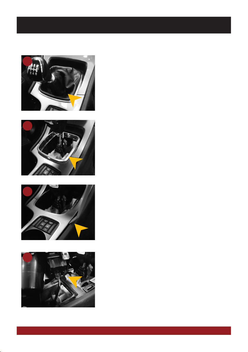
Einbautipps:
Installation hints:
8
7
TMC cable antenna:
Connect the enclosed TMC antenna (15) with a free USB port on and then lay
the antenna. For optimal reception it should be fastened to the windscreen
by using the suction cups, a hidden installation e.g. under the A-pillar or the
dashboard is also possible.
TMC Kabelantenne:
Schließen Sie die beiliegende TMC Antenne (15) an einen freien USB Anschluss
an und verlegen Sie dann die Wurfantenne. Für optimalen Empfang kann diese
an der Scheibe mithilfe der Saugnäpfe befestigt werden, auch ein verstecktes
Verlegen z.B. unter der A-Säule oder unter dem Armaturenbrett ist möglich.
15

9
INSTALLATION NOTES / Installationshinweise
Handbrake connection:
Depending on the type of vehicle the CAN-BUS sends the information of the
handbrake signal to the ESX device. If this is not the case, the included cable
handbrake connection needs to be connected. The signal must be connected
with ground while the handbrake is applied. Please contact for a proper and
safe installation your car dealer! According to legal regulations, the device
must playback a DVD or video on the main screen only with the handbrake
applied, Never connect the the cable permanently with the vehicle‘s ground. To
prevent accidents by inattention while driving, the screen is blanked.The video
outputs are not affected.
Handbremsen-Anschluss:
Je nach Fahrzeugtyp sendet der CAN-BUS die Information des Handbremsen-
signals an das ESX Gerät. Sollte dies nicht der Fall sein, muss das beiliegende
Kabel Handsbremsen-Anschluss angeschlossen werden. Das Signal muss bei
angezogener Handbremse auf Masse liegen. Bitte wenden Sie sich für eine
korrekte und gefahrlose Installation an Ihre KFZ-Fachwerkstatt! Gemäß den
gesetzlichen Bestimmungen darf das Gerät eine DVD bzw. Videowiedergabe
auf dem Hauptbildschirm nur bei angezogener Handbremse wiedergeben,
das Anschlusskabel darf deshalb nicht dauerhaft auf Masse angeschlossen
werden. Während der Fahrt wird der Bildschirm zur Vermeidung von Unfällen
durch Unachtsamkeit dunkel geschaltet Die Videoausgänge sind hiervon nicht
betroffen.
USB Inputs:
Route the USB inputs to a desired location, such as the glove box. If necessary,
you must drill openings. One of the USB inputs is needed for the TMC antenna
(8), the other input can be connected with the original factory USB input (refer
to page 12/13) by using the ESX USB adapter (10).
USB Anschlüsse:
Verlegen Sie die USB Anschlüsse an den gewünschten Einbauort, wie z.B. im
Handschuhfach. Gegebenenfalls, müssen dafür Öffnungen gebohrt werden.
Einer der USB Anschlüsse wird für die TMC Antenne (8) benötigt. der andere
Anschluss kann mit dem ESX USB-Adapter (10) mit dem werksseitigen USB-
Anschluss verbunden werden (Siehe Seite 12/13).

10
INSTALLATION EXAMPLE / Einbaubeispiel
2.) Carefully clip out the silver decoration frame.
2.) Clipsen Sie vorsichtig den silbernen Zierrahmen heraus.
1
3.) Unlock the cup holder unit all around by using a mounting wedge.
3.) Entriegeln Sie die Getränkehaltereinheit ringsum mithilfe eine Montagekeils.
2
3
4.) Lift up the cup holder unit and remove the connector of
the heated seats (if equipped).
4.) Heben Sie die Getränkehaltereinheit heraus und entfernen Sie
den Stecker der Sitzheizung (falls vorhanden).
4
1.) Loosen the shift boot on the gear shift.
1.) Lockern Sie den Schaltsack an der Gangschaltung.
FORD MONDEO BA7 (06/2007 >)

11
6.) Remove the six fixing screws all around the radio unit.
6.) Entfernen Sie die sechs Befestigungsschrauben rings um die Radioeinheit.
5
7.) Remove the radio panel by using mounting wedges.
7.) Entfernen Sie die Radioblende mithilfe von Montagekeilen.
6
7
8.) Then unplug the three connectors from the radiopanel.
8.) Ziehen Sie dann die drei Stecker an der Radioblende ab.
8
5.) Remove the left and the right decoration panel next to the radio by using
mounting wedges.
5.) Entfernen Sie die linke und rechte Zierblende neben dem Radio mithilfe
von Montagekeilen.
INSTALLATION EXAMPLE / Einbaubeispiel
FORD MONDEO BA7 (06/2007 >)

12
INSTALLATION EXAMPLE / Einbaubeispiel
10.) Slightly pull out the radio from the radio bay and disconnect all plugs.
10.) Ziehen Sie den Radio vorsichtig aus dem Radioschaft und klemmen
alle Stecker ab.
9
11.) Now remove the glovebox by using a torx 20 screwdriver (4 screws)
and a 10 mm nut (2 screws).
11.) Bauen Sie dann das Handschuhfach aus und verwenden Sie dafür
einen Torx 20 Schraubendreher (4 Schrauben) sowie eine 10 mm
Nuss (2 Schrauben).
10
11
12.) Above the glovebox you find a blackbox, which is fixed with a T20 screw.
Remove the box and disconnect the USB connector.
12.) Über dem Handschufach befindet sich eine Blackbox welche mit
einer TX20 Schraube befestigt. Schrauben Sie die Box ab und ziehen
Sie hier den USB Anschluss ab.
12
9.) Remove the four fixing screws of the radio.
9.) Entfernen Sie die vier Befestigungsschrauben des Radios.
FORD MONDEO BA7 (06/2007 >)

13
14.) Lay the connection cable sets of new ESX device (refer to page 4-5)
inside the vehicle to the desired location and connect these according
with the sockets on the new ESX device. Plug in also the huge car specific
and the antenna connector. If necessary us the optional Fakra antenna
adapter (refer to page 2).
14.) Verlegen Sie nun die Anschlusskabel des neuen ESX Geräts (siehe S. 4-5) im
Fahrzeug zum gewünschten Einbauort und schließen diese entsprechend
am neuen ESX Gerät an. Schließen Sie ebenfalls den großen fahrzeug-
spezifischen Kabelstecker und den Antennenstecker an. Falls nötig benutzen
Sie den optionalen Fakra-Antennenadapter (Siehe S. 2)
13
15.) Push the new ESX device into the radio bay.
15.) Schieben Sie das neue ESX Gerät in den Radioschacht.
14
15
16. Before you complete the installation of the new ESX device, check its function.
Please note that it may take up to 15 minutes, until a GPS signal can be
received (in the open). After the successful check of the functions,
re-assemble the new device in the reverse order (steps 1-9).
16. Prüfen Sie vor dem Zusammenbau das neue ESX Gerät auf seine Funktion.
Bitte beachten Sie, dass es bis zu 15 Minuten dauern kann, bis ein
GPS Signal (unter freiem Himmel) empfangen werden kann. Führen Sie
nach erfolgreicher Prüfung der Funktionen dann den Zusammenbau (1-9)
in umgekehrter Reihenfolge durch.
16
13.) Now connect here the ESX USB adaptor (10).
Then re-assamble the black box and the glove box.
13.) Schließen Sie hier nun den ESX USB-Adapter (10) an.
Dann montieren Sie die Blackbox und das Handschuhfach wieder an.
INSTALLATION EXAMPLE / Einbaubeispiel
FORD MONDEO BA7 (06/2007 >)

14
NOTES / Notizen

15
NOTES / Notizen

DESIGN
ESX Car Media Systems · Audio Design GmbH
Am Breilingsweg 3 · D-76709 Kronau/Germany
Tel. +49 7253 - 9465-0 · Fax +49 7253 - 946510
www.esxnavi.de - www.audiodesign.de
©2017 All Rights Reserved
Table of contents
Other ESX Car Receiver manuals

ESX
ESX VNC730 FI-DUCATO User manual

ESX
ESX VISION ANDROID Series User manual

ESX
ESX VN630W User manual

ESX
ESX Vision Naviceiver VN610 TO-U1 User manual

ESX
ESX VN710 MB-A2 User manual

ESX
ESX VISION NAVICEIVER VN710 LX-CT200h-DAB User manual

ESX
ESX XE1200C User manual

ESX
ESX VN709 OP-INSIGNIA User manual

ESX
ESX VN720 VW-U1 User manual

ESX
ESX VN710 HY-i40 User manual

ESX
ESX QXS6.3C User manual

ESX
ESX VN830 SK-OC3 User manual

ESX
ESX VN710 VW-P1 User manual

ESX
ESX VNC711 FI-DUCATO User manual

ESX
ESX VN710 MB-A1 User manual

ESX
ESX VN710 LX-CT200h User manual

ESX
ESX VN710-CV-AVEO User manual

ESX
ESX VISION ANDROID Series User manual

ESX
ESX VN720 HY-iX35 User manual

ESX
ESX Vision Naviceiver VN735 VO-U1 User manual