8
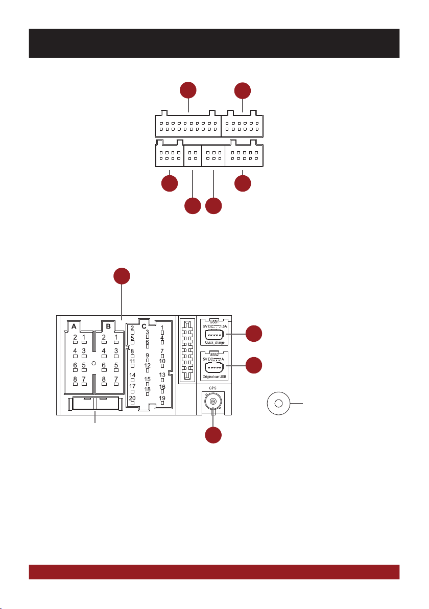
CONNECTION DIAGRAM / Anschlussdiagramm
IMPORTANT NOTE: On vehicles with radio preparation and ISO connectors usually a „Plug and Play“ installation is possible. In this
case, it is important that the ESX Naviceiver is connected with the ignition plus (ACC, PIN 7).
ATTENTION: Never use the CANBUS together with ignition plus.
FUSE: In case of a defect, the fuse must be replaced with a fuse of the same value (10A). Eliminate the cause of the short circuit
before replacing the defective fuse.
ASSIGNMENT OF THE ACCESSORY CONNECTORS
Audio / Video / AV Inputs G71-AUD0119
Name Connector/Color Function
AV1-L-IN RCA white AV Audio left in AV/TV menu
AV1-R-IN RCA red AV Audio right in AV/TV menu
AV1-V-IN RCA yellow AV Video in AV/TV menu
AV2/TV-L-IN RCA white AV2 Audio left in AV/TV menu
AV2/TV-R-IN RCA red AV2 Audio right in AV/TV menu
AV2/TV-V-IN RCA yellow AV2 Video in AV/TV menu
AV3/AUX1-L-IN RCA white AV3 Audio left in AV/TV menu
AV3/AUX1-R-IN RCA red AV3 Audio right in AV/TV menu
AV3-V-IN/VIDEO RCA yellow AV3 Video in AV/TV menu
+12V OUT yellow 12V Output
Power supply for external devices such as DVB-T tuners.
Maximum current consumption 500 mA.
GND plack Ground wire to +12V OUT
TV-CONT-OUT brown Control cable for special ESX devices, please do not use.
BRAKE IN pink Connect to the parking brake signal to the device.
The cable provides ground when the parking brake is operated.
Please do not use if the CANBUS is used, CANBUS has always priority.
Audio – Outputs 5.1 with Remote Turn On G71-MNV0010
Name Connector/Color Function
FL-OUT RCA white Pre-amplifier output front left
FR-OUT RCA red Pre-amplifier output front right
RL-OUT RCA white Pre-amplifier output rear left
RR-OUT RCA red Pre-amplifier output rear right
SUBWOOFER-OUT RCA brown Pre-amplifier output Subwoofer (Mono)
CENTER-OUT RCA yellow Pre-amplifier output Center (Mono)
AMP-CONT-OUT green Remote Turn On output
12V output to turn on an external amplifier.
Maximum current consumption 500 mA.
Various System Connections G71-WHE0063
Name Connector/Color Function
Uart/+5V OUT black Reserved, please do not use!
SWC1IN red-white For an analog steering wheel signal. Please do not use!
SWC2IN green-white For an analog steering wheel signal. Please do not use!
ILL IN orange Illumination signal „ILL“ input. Same function as ILL on the ISO plug.
ANT-POWER OUT yellow 12V output for FM antenna amplifiers. Attention! The power supply is only active
while the FM function of the device is activated. Max. Current consumption 100 mA.
ENGLISH
6
7
5