VE6.2W KICKBASS WOOFER
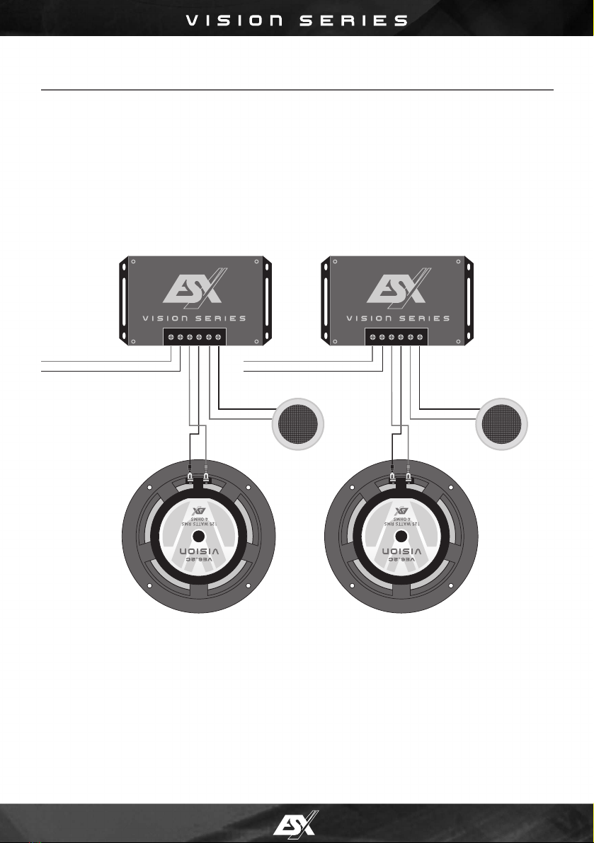
WIRING DIAGRAM
ANSCHLUSS-DIAGRAMM
IMPORTANT / ACHTUNG
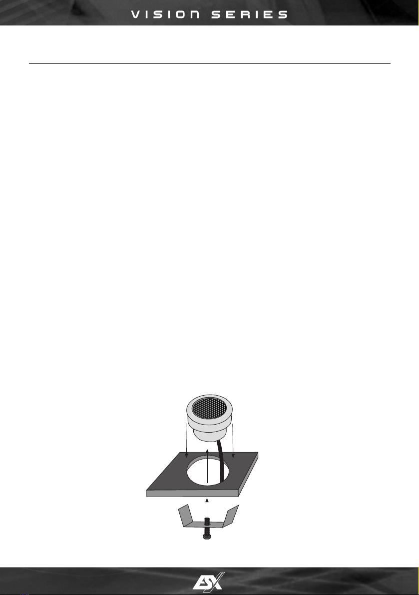
The VISION VE Speaker Components are made out of very precious materials like aluminum cones
and aluminum tweeter housings. Don’t touch the aluminum cone with fingers or spikey devices.
Please handle with care during the installation, otherwise the Components will get damaged.
Die VISION VE Komponenten sind aus sehr hochwertigen Materialien wie Aluminium-Membranen
und -Hochtöner-Gehäusen gefertigt. Berühren Sie die Aluminium-Mebranen nicht mit den Fingern oder
spitzen Gegenständen. Bitte behandeln Sie die Komponenten mit Sorgfalt während des Einbaus, andernfalls
könnten diese ernsthaft beschädigt werden.
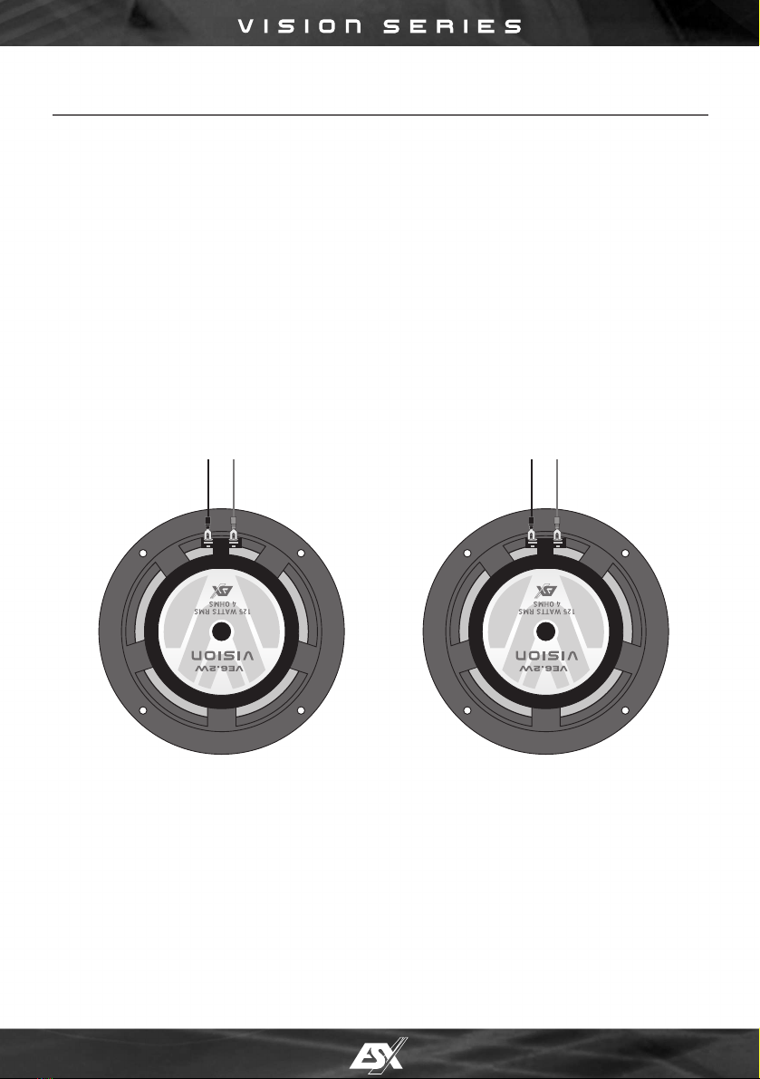
PLEASE ENSURE ALWAYS CORRECT POLARITY FOR ALL CONNECTIONS.
NEVER CONNECT SPEAKERS (–/+) TO GROUND OR VEHICLE’S CHASSIS.
BITTE BEACHTEN SIE STETS DIE RICHTIGE POLARITÄT DER ANSCHLÜSSE.
SCHLIESSEN SIE DIE LAUTSPRECHER (–/+) NIEMALS AN MASSE ODER DIE KFZ-KAROSSERIE AN.
KICKBASS LEFT
KICKBASS LINKS KICKBASS RIGHT
KICKBASS RECHTS
RIGHT CHANNEL OF AMPLIFIER WITH A
LOWPASS FREQUENCY RANGE OF 150 HZ UP TO 500 HZ.
THE SUBSONICFILTER FREQUENCY SHOULD
BE SET TO CA. 40 HZ, IF AVAILABLE.
RECHTER KANAL DES VERSTÄRKERS MIT EINEM
TIEFPASS-FREQUENZBEREICH VON 150 BIS 500 Hz.
DIE SUBSONICFILTER FREQUENZ SOLLTE BEI CA. 40 HZ.
LIEGEN (FALLS VORHANDEN).
+ – + –
LEFT CHANNEL OF AMPLIFIER WITH A
LOWPASS FREQUENCY RANGE OF 150 HZ UP TO 500 HZ.
THE SUBSONICFILTER FREQUENCY SHOULD
BE SET TO CA. 40 HZ, IF AVAILABLE.
LINKER KANAL DES VERSTÄRKERS MIT EINEM
TIEFPASS-FREQUENZBEREICH VON 150 BIS 500 Hz.
DIE SUBSONICFILTER FREQUENZ SOLLTE BEI CA. 40 HZ.
LIEGEN (FALLS VORHANDEN).