Impact Instrumentation 326M Series User manual

INSTRUCTION
MANUAL
OPERATION
&
SERVICE
326M
SERIES
SUCTION
APPARATUS,
SURGICAL,
AND
GASTROINTESTINAL
ABDOMINAL
DRAINAGE
PORTABLE,
AC/DC/RECHARGEABLE
BATTERY
CONTRACT
NO.
SPO200-98-D-8703
IMPACT
INSTRUMENTATION,
INC.
Rev.
G
(12/00)
Manual
P/N
906-0326-03

TABLE
OF
CONTENTS
SUBJECT
LIST
OF
ILLUSTRATIONS
SHIPPING
CONTENTS
ACCESSORIES
LIST
LIMITED
COPYRIGHT
RELEASE
CALIBRATION
NOTICE
UNPACKING
LOCATION
OF
USE
WARNINGS
REGARDING
USE
ASSEMBLY,
INTERCONNECTIONS
AND
INITIAL
ADJUSTMENTS
ASSEMBLY
INTERCONNECTIONS
INITIAL
ADJUSTMENTS
USAGE
APPLICATIONS
SECTION
I.
OPERATION
INTRODUCTION
OPERATION
DESCRIPTION
OF
CONTROLS,
CIRCUIT
BREAKER,
CONNECTORS
AND
INDICATORS
OPERATING
POWER
SELECTION
&
STOPPING
SUCTIONING
VACUUM
REGULATOR
(LIMITER)
COLLECTION
CANISTER
OPERATOR
PERFORMANCE
CHECKS
BATTERY
CARE
ROUTINE
CARE
AND
MAINTENANCE
CLEANING
Component
Removal
Exterior
Case
Collection
Canister
Hydrophobic/Bacterial/Overflow
Filter
MAINTENANCE
IN
CASE
OF
DIFFICULTY
OPERATOR
CORRECTIBLE
PROBLEMS
OPERATOR
PROBLEMS
REQUIRING
SERVICE
STORAGE
INFORMATION
PAGE
iii
vi
vi
vi
vi
vi
viii
1-1
1-1
1-1
2-1
3-1
4-1
5-1

TABLE
OF
CONTENTS
(CONT’D)
SUBJECT
LIMITED
WARRANTY
SPECIFICATIONS
SECTION
II
SERVICE
INTRODUCTION
CAUTIONARY
NOTES
OPERATING
VOLTAGES
PRECAUTION
INTERNAL
RECHARGEABLE
BATTERY
HELPFUL
HINTS
DISASSEMBLY/REASSEMBLY
BOTTOM
COVER
BATTERY
COMPARTMENT,
CLEAR
FRONT
COVER
&
TOP
COVER
SWITCHER
PRINTED
CIRCUIT
BOARD
REGULATOR
PRINTED
CIRCUIT
BOARD
MAIN
PRINTED
CIRCUIT
BOARD
CONNECTOR
PANEL
PUMP/MANIFOLD
FRONT
PANEL
CALIBRATION
PROCEDURE
REQUIRED
EQUIPMENT
PROCEDURES
CIRCUIT
DESCRIPTIONS
EXTERNAL
AC
POWER
SUPPLY
INTERNAL
POWER
SUPPLIES
DC
TO
DC
CONVERTER
6-VOLT
POWER
SUPPLY
5-VOLT
&
25.6-VOLT
POWER
SUPPLIES
ISOLATED
6-VOLT
POWER
SUPPLY
PUMP
CIRCUIT
SOLENOID
CIRCUITS
TIMING
CIRCUITS
BATTERY
CHARGER
CIRCUIT
BATTERY
LEVEL
MONITORING
CIRCUIT
PREVENTATIVE
MAINTENANCE
INSPECTIONS
VISUAL
CHECKS
PERFORMANCE
CHECKS
CLEANING
TROUBLESHOOTING
GUIDE
TECHNICAL
DOCUMENTATION
BLOCK
DIAGRAM
BILLS
OF
MATERIAL
WIRING
DIAGRAM
&
ELECTRICAL
SCHEMATICS
WIRE
LIST
IMPACT
INSTRUMENTATION,
INC.,
27
Fairfield
Place
West
Caldwell,
NJ
07006
aie
PAGE
5-1
6-1
7-1
7-1
10-1
12-1
13-1

LIST
OF
ILLUSTRATIONS
FIGURE
#
DESCRIPTION
PAGE
iN
Model
326/326M
Main
Features
iv
2-
Interconnection
Diagrams
vii
Suction
Apparatus
shown
with
hydrophobic/bacterial/overflow
filter
3
Panel
Controls,
Circuit
Breaker,
Connectors
and
Indicators
1-1
4.
Composite
Illustration
Depicting
Major
Sub-Assemblies
13-1
至
Bottom
Cover
Assembly
13-2
6.
Top
Cover
Assembly
13-3
Pã
Connector
Panel &
Battery
Pack
Assemblies
13-4
8.
Pump
&
Manifold
Assemblies
13-5
9.
Front
Panel
Assembly
13-6
10.
AC
Charger
Rectifier
Assembly
13-7
11.
Collection
Canister
&
Auto
Power
Cable
Assemblies
13-8
12.
Wire
Harness
Assembly
13-9
19.
Accessory
Kit-Air
Force
Assembly
13-10
14.
Accessory
Kit-Army
Assembly
13-11
15:
Switcher
Printed
Circuit
Board
Assembly
13-12
16.
Regulator
Printed
Circuit
Board
Assembly
13-13
17.
Main
Printed
Circuit
Board
Assembly
13-14
18.
Block
Diagram
13-15
Wiring
Diagram
&
Electrical
Schematics
(5
pages)
-
iii
-
13-37
thrul3-41

Injection
Molded
Case
Dual-Scale
Vacuum
Gauge
Carrying
Handle
Circuit
Breaker
Vacuum
Inlet
Fitting
External
Power
Input
Jack
a
a
TS
Va
c
| |
U
External
Power
Suction
Interval
n
Lamp
Timer
Controls
TT
lle
soma
Pal
TTT
로
E .
0
.
>
.
0
©
|
10
Di
„©
Battery
Charge
_|||1Il_
一
© ©
(+)
rel
.
개
BATTERY
CHARGE
MODE
M
i
o|
PS
Power
€
Mode
レレ
に
Selector
Switch
Charge
Lamp
<|
,
©
i
+
IMPACT
«
Collection
Canister
Mounting
Bracket
Vacuum
Regulator
VE
Collection
Canister
Mounting
Bracket
FIGURE
1
MODEL
326/326M
MAIN
FEATURES
df:
326MFIG1.CDR
(Rev
0,
04/97)

SHIPPING
CONTENTS
Each
Model
326
is
shipped
with
the
following
contents:
.
Apparatus,
Suction,
Portable
lea.
Hose,
Clear,
PVC,
1’
Long
Assembly, Auto
Power
Cable
lea.
Hose,
Clear,
PVC,
18"
Long
Suction
Hose,
Sterile,
Clear,
6’
Long
lea.
Hose,
Clear,
PVC,
2’
Long
.
AC/DC
Power
Supply
(115/230
VAC,
lea.
Universal
Canister
Attachment
Bracket
50/60/400
HZ
input;
nominal
lea.
Fuse,
Spare
12
VDC
output)
lea.
Instruction
Manual,
Operation
Each
Model
326M
is
shipped
with
the
following
contents:
lea.
Apparatus,
Suction,
Portable
The
following
are
provided
with
NSN
6515-01-435-0050
lea.
Assembly,
Auto
Power
Cable
lea.
Suction
Hose,
Sterile,
Clear,
6’
Long
2ea.
Collection
Canister
Assembly,
Autoclavable
2ea.
Fuse,
Spare
2ea.
Filter,
Disposable,
Hydrophobic/Bacterial/Overflow
lea.
AC/DC
Power
Supply
(115/230
VAC,
(for
use
with
reusable
canisters
only)
50/60/400
HZ
input;
nominal
lea.
Carry-all
Case
with
Label
12
VDC
output)
lea.
Hose,
Clear,
PVC,
1’
Long
The
following
are
provided
with
Air
Force
Accessory
Kit
2ea.
Hose,
Clear,
PVC,
18"
Long
2ea.
Hose,
Clear,
PVC,
2’
Long
2ea.
Disposable
Collection
Canister
&
Lid
2ea.
Universal
Canister
Attachment
Bracket
lea.
Catheter,
14
French
2ea.
Instruction
Manual,
Operation
&
Service
1ea.
Catheter,
18
French
lea.
Case,
Padded,
Aspirator
2ea.
Strap,
Velcro®
ACCESSORIES
LIST
The Accessories
List
contains
common
items,
required
from
time
to
time.
Each
item
is
preceeded
by
its
part
number.
Accessories
may
be
ordered
direct
from
Impact.
When
ordering,
please
include
the
part
number,
description
and
quan-
tity
required.
Send
written
purchase
orders
to:
Impact
Instrumentation,
Inc.
P.O.
Box
508
Telephone
orders:
973/882-1212
27
Fairfield
Place
FAX
orders:
973/882-4993
West
Caldwell,
New
Jersey
07006
PART
NUMBER
“DESCRIPTION
465-0005-00
Filter,
Disposable,
Hydrophobic/Bacterial/Overflow
540-0068-00
Hose,
Clear,
PVC,
1’
Long
540-0055-00
Hose,
Clear,
PVC,
18"
Long
540-0051-00
Hose,
Clear,
PVC,
2’
Long
703-0326-07
Assembly,
Collection
Jar
703-0326-06
AC/DC
Power
Supply
820-0018-00
Tubing,
Suction,
Sterile,
9/32"
LD. X
6”
906-0326-03
Instruction
Manual,
Operation
&
Service,
Model
326M
906-0326-01
Instruction
Manual,
Operation,
Model
326
906-0326-04
Instruction
Manual,
Operation
&
Service,
Model
326
LIMITED
COPYRIGHT
RELEASE
Permission
is
hereby
granted
to
the
Department
of
Defense
to
reproduce
all
material
furnished
under
this
contract
for
use
in
a
military
service
training
program
and
other
technical
training
programs.

CALIBRATION
NOTICE
_
This
device
should
be
incorporated
ito
a
regular
preventative
maintenance program
to
insure
compliance
with
operat-
ing
specifications.
Calibration
measurements
should
be
made
on
a
biannual
basis
unless
significant
usage
warrants
a
shorter
period
between
preventative
maintenance
inspections.
A
calibration
check
should
be
made
following
each
DER
of
300
hours
of
operation.
Recommended
maintenance
checks
can
be
found
in
the
SERVICE
section
οἱ
anual.
UNPACKING
Check
the
contents
of
the
shipping
case(s)
against
the
enclosed
packing
list.
Examine
the
instrument
for
any
obvious
signs
of
shipping
damage.
If
there
is
no
apparent
sign
of
mechanical
damage,
read
the
instructions
contained
within
this
manual
before
attempting
to
operate
the
instrument.
LOCATION
OF
USE
The
Model
326/326M
is
a
transportable
device,
therefore,
its
physical
area
of
use
will
vary.
When
operated
in
a
wet
en-
vironment,
a
should
take
precautions
and protect
this
device
by
covering
it
with
a
protective
barrier
(small
tarp, plas-
tic
sheet,
etc.).
WARNINGS
REGARDING
USE
Caution:
Federal
law
restricts
this
device
to
sale
by
or
on
the
order
of
a
physician.
This
equipment
is
intended
for
use
by
qualified
medical
personnel
or
person(s)
under
the
guidance
and
instruction
of
certified
medical
therapists.
Danger
-
Possible
explosion
hazard
if
used
in
the
presence
of
flammable
anesthetics.
Caution
-
Electric
shock
hazard,
do
not
remove
inside
cover.
Refer
servicing
to
qualified
biomedical
equipment
tech-
nicians
only.
See
section
entitled
SERVICE.
Do
not
operate
this
instrument
prior
to
reading
the
instructions
contained
within
this
manual.
Disposable
hydrophobic/bacterial/overflow
filter
is
for
use
only
with
reusable,
autoclavable,
collection
canisters.
Do
not
clean
collection
canister
with
abrasive
cleansers
or
(See
ROUTINE
CARE
AND
MAINTENANCE
section
CLEANING).
ASSEMBLY,
INTERCONNECTIONS
AND
INITIAL
ADJUSTMENTS
ASSEMBLY:
No
assembly
is
required
before
placing
this
device
into
operation.
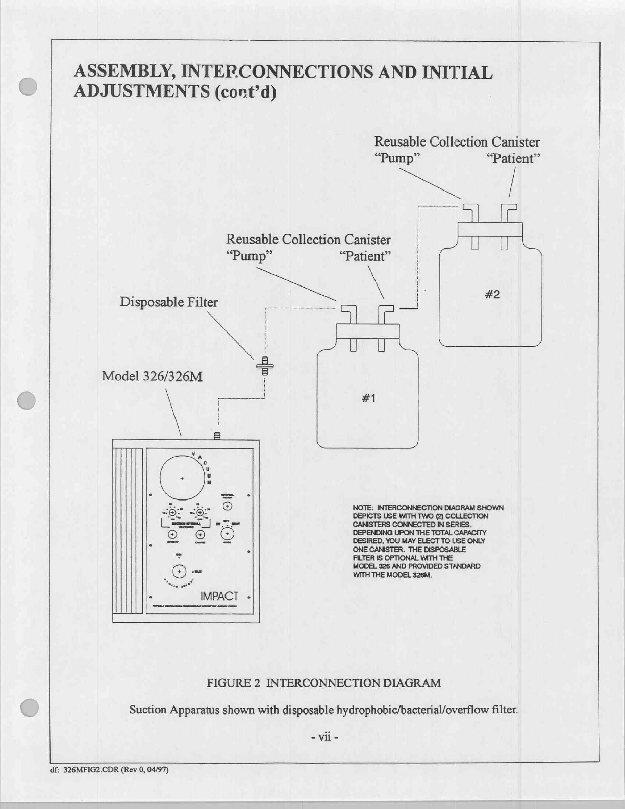
INTERCONNECTIONS:
Tubing
interconnections
are
required
before
placing
this
device
into
operation.
Figure
2
depicts
the
interconnections
required
to
connect
the
Model
326/326M
to
the
reusable
collection
canisters
(in
series)
and
disposable
hydrophobic/bacterial/overflow
filter.
INITIAL
ADJUSTMENTS:
Before
placing
this
device
into
operation
read
the
section
entitled
OPERATION,
|
DESCRIPTION
OF
CONTROLS,
CIRCUIT
BREAKER,
CONNECTORS
AND
INDICATORS.
Make
control
settings
and
verify
device
performance
prior
to
interfacing
with
patient.
i
ASSEMBLY,
INTERCONNECTIONS
AND
INITIAL
ADJUSTMENTS
(cont’d)
Reusable
Collection
Canister
“Pump”
Disposable
Filter
Model
326/326M
Reusable
Collection
Canister
“Pump”
πε
(l
im
“Patient”
AE
ML
#1
IMPACT
-
FILTER
IS
OPTIONAL
WITH
THE
WITH
THE
MODEL
326M.
FIGURE
2
INTERCONNECTION
DIAGRAM
“Patient”
|
U
U
#2
NOTE:
INTERCONNECTION
DIAGRAM
SHOWN
DEPICTS
USE
WITH
TWO
(2)
COLLECTION
CANISTERS
CONNECTED
IN
SERIES.
DEPENDING
UPON
THE
TOTAL
CAPACITY
DESIRED,
YOU MAY
ELECT
TO
USE
ONLY
ONE
CANISTER.
THE
DISPOSABLE
MODEL
326
AND
PROVIDED
STANDARD
Suction
Apparatus
shown
with
disposable
hydrophobic/bacterial/overflow
filter.
-
vii
-
df:
326MFIG2.CDR
(Rev
0,
04/97)

USAGE
APPLICATIONS
-
DEEP
DRAINAGE/GASTRO-INTESTINAL
SUCTION
IMPACT
MODELS
306/306M
AND
326/326M
PORTABLE
ASPIRATORS
Deep
drainage/gastro-intestinal
suction,
frequently
referred
to
as
Wangensteen
suction
(after
Dr.
Owen
H.
Wangensteen*),
requires
a
thorough
understanding
of
"mild
suction"
procedures
including
collection
bottle
placement
and
tubing
lengths.
The
following
data
is
for
reference
only
and
specific
applications
may
warrant
deviations
and/or
additional
considerations.
The
Impact
Models
306/306M
and
326/326M
are
capable
of
maintaining
precise
vacuum
and
airflow
levels.
ON/OFF
cycling
times
may
be
varied
from
patient
to
patient
effectively
optimizing
drainage
intervals.
Cycling
oe
are
ea
arbitrary.
It is
recommended
that the
user
select
intervals
consistent
with
past
practices
and
protocols.
The
gastro-intestinal
tract
represents
a
pliable
area
which
when
subjected
to
continuous
negative
pressure
will
collapse
around
an
implanted
drainage
tube.
Such
a
collapse
can
cause
continuous
suction
in
a
specific
tissue
area,
thus
preventing
additional
drainage
while
fluids
accumulate
and
potential
ulcerations
can
lead
to
perfora-
tions
and
hemorrhage
at
the
collapsed
site.
The
intended
action
of
intermitte
at
suction
is
to
provide
a
hydraulic
effect
whereby
drainage
fluids are
pulled
and
pushed
during
ON
and
OFF
cycles.
The
"pull"
effect
occurs
as
suction
is
applied
to
the
gastro-intestinal
tract,
thus
removing
accumulated
fluids.
The
"push"
effect
occurs
when
fluid
in
the
elevated
connecting
tubing
(18"
maximum
height)
flows
back
into
the
drainage
site,
washing"
the
implanted
catheter
away
from
the intes-
tinal
wall,
thus
relocating
it
in
time
for
the
next
ON
cycle.
It
is
important
to
note
that
the
height
of
the
collection
canister
and
placement
"dressing”
of
the
connecting
tubing
each
has
a
critical
effect on
overall
performance.
Under
normal
conditions,
vacuum
levels
of
90
mmHg
and
120
mmHg
would
raise
a
column
of
water
approximately
4’
and
5’
respectively.
It
is
possible
that
mild
suc-
tion,
involving
particulate
matter
(solids),
blood
clots,
and viscous
secretions
could
present
a
situation
whereby
the
delivered
suction
strength
can
only
raise
the
drained
contents
to
a
height
of
roughly
3’
to
4’.
To
compensate
for
this
effect,
the
user
is
cautioned
not
to
exceed
an
18"
height
between
collection
bottle
entry
point
and
the
dis-
tal
end
of
the
implanted
suction
catheter.
The
user
should
also
be
discouraged
from
using
excessive
lengths
of
connecting
tubing.
Since
mild
suction
consists
of
minimal
airflow,
excessive
tubing
lengths
could
prevent
fluid
from
actually
entering
the
collection
canister
prior
to
the
beginning
of
the
next
OFF
cycle.
The
actual
length
of
the
ON
cycle
can
be
extended
to
compensate
for
this,
however,
the
clinician
must
always
recognize
that
an
in-
creased
possibility
of
tissue
occlusion
exists.
The
hydraulic
action
previously
discussed
is
only
possible
when
the
collection
canister
is
at
a
height
greater
than
the
distal
end
of
the
implanted
catheter.
During
OFF
cycles,
the
Models
306/306M
and
326/326M
vent
to
atmospheric
pressure,
enabling
a
gravitational
backflow
to
occur.
If
the
collecting
jar
is
positioned
below
the
height
of
the
distal
end
of
the
implanted
catheter,
a
siphoning
effect
can
occur.
Siphoning
will
act
as
a
con-
tinuous
suction
presence
between
patient
and
collection
canister
which
is
undesireable.
Cycling
between
the
Models
306/306M
and
326/326M
and
collection
canister
will
continue
despite
siphoning.
Clinicians
may
have
visual
objections
to
the
appearance
of
drained
fluids
and
seek
options
regarding
collection
canister
placement.
The
factors
involving
the
time
cycles
(ON
and
OFF),
collection
canister
height
and
connecting
tubing
must
be
considered
in
order
to
have
safe,
effective
intermittent
suction.
*"INTESTINAL
OBSTRUCTIONS"
by
Owen
H.
Wangensteen,
M.D.,
C.C.
Thomas,
Publisher,
Springfield,
Illinois:
Chapter
VI.
df:
326USAGE.CHP
vio

SECTION
L
OPERATION
INTRODUCTION
The
Impact
Model
326/326M
is
a
self-contained,
multi-purpose,
suction
apparatus
designed
for
removing
secretions
from
the
upper
airway
during
oropharyngeal,
nasopharyngeal
and
tracheal
suctioning
procedures;
programmable
gastrointestinal
and
abdominal
wound
drainage;
or
surgical
site
debris
in
field
hospitals.
The
apparatus
includes
EMI/RFI
suppression
circuitry
and
is
suitable
for
use
in
desert,
tropic,
arctic
or
aeromedical
environments.
Simul-
taneous
operation
and
battery
recharge
is
permitted
from
either
115/230
VAC,
50-400
hz
using
the
provided
AC-DC
Power
Supply
or
12
VDC
using
the
provided
Auto
Power
Cable
accessories.
Simultaneous
operation
and/or
recharge
from
aircraft
electrical
systems
(24
to
28
VDC)
is
permissible
with
an
appropriate
cable.
The
Model
326/326M
is
designed
to
accept
DC
power
sources ranging
from
11 to
30
volts,
positive
or
negative
ground.
The
Model
326/326M
is
a
completely
self-contained
suction
source
complete
with
vacuum
pump,
controls
and
DC
power
supply
circuits;
a
dual-scale
vacuum
gauge
with
adjustable
vacuum
regulator
(limiter);
circuit
breaker,
collection
canister
mounting
brackets,
accessories
and
attachment
tubing
is
provided.
The
complete
device
is
housed
within
an
in-
jection
molded
case
which
includes
a
locking
battery
compartment
door,
a
locking
control
panel
door
(clear),
carrying
handle
and
mounting
interface
for
wall,
bulkhead,
pole
or
cart
mounting.
This
device
is
intended
for
use
in
non-explosive
atmospheres.
Read
the
instructions
contained
within
this
manual
before
attempting
to
operate
this
instrument.
OPERATION
DESCRIPTION
OF
CONTROLS,
CIRCUIT
BREAKER,
CONNECTORS
AND
IN-
DICATORS
Refer
to
the
reference
pictorial
below.
Numbers
contained
within
this
text
(in
parenthesis)
correspond
to
the
numbers
indicated
in
the
pictorial.
(1)
Circuit
Breaker
(4)
(1) (2)
(3)
и
8
Z
(2)
Vacuum
Inlet
Fitting
(3)
External
Power
Input
Jack
с,
(4)
Dual-scale
Vacuum
Gauge
(5)
| A
し
(11)
(5)
"ON
TIME”
Suction
Interval
Control
a
[ῃ
ia
(6)
"OFF
TIME"
Suction
Interval
Control
a
(6)
(7)
Battery
Charge
Indicator
a
0)
|
jin
(9)
(8)
Charge
Lamp
T
O
cene
®
(9)
Power
&
Mode
Selector
Switch
i
=
IMPACT
-
(10)
Vacuum
Regulator
Control
ei
E
(11)
External
Power
Lamp
Figure
3.
Fanel
Controls,
Circuit
Breaker,
Connectors
and
Indicators
1-1

OPERATION
(cont'd)
DESCRIPTION
OF
CONTROLS,
CIRCUIT
BREAKER,
CONNECTORS
AND
IN-
DICATORS
(cont'd)
(1)
Circuit
Breaker
-
Protects
pump
motor
from
drawing
excessive
current.
(2)
Vacuum
Inlet
Fitting
-
Vacuum
source
connection
to
filter
and
collection
canister(s).
(3)
External
Power
Input
Jack
-
Connection
for
external
operating
and
battery
recharging
power.
Input
accomodates
11
to
30
VDC
input,
positive
or
negative
ground.
(4)
Dual-scale
Vacuum
Gauge
-
Displays
vacuum
developed
within
the
patient
circuit.
(5)
"ON
TIME"
Suction
Interval
Control
-
Setting
determines
how
long
intermittent
suction
will
last.
(6)
"OFF
TIME"
Suction
Interval
Control
-
Setting
determines
how
long
before
the
next
intermittent
cycle
begins.
(7)
Battery
Charge
Indicator
-
Displays
battery
charge
status.
Green
area
portrays
the
charged
zone,
the
red
area
portrays
the
discharged
zone.
(8)
Charge
Lamp
-
Indicates
the
presence
of
battery
charging
current
from
an
external
power
source.
(9)
Power
&
Mode
Selector
Switch
-
Turns
operating
power
Off
or
On
when
the
continuous
"CONT"
or
intermittent
"INT"
suction
mode
is
selected.
CONT
-
Selects
continuous
suctioning,
vacuum
adjustable
from
0
to
550
mmHg
INT
-
Selects
intermittent
suctioning,
vacuum
adjustable
from
0
to
200
mHg.
Time
interval
combinations
are
selectable
between
5
and
40
seconds
ON,
and
5
and
40
seconds
OFF.
(10)
Vacuum
Regulator
(Limiter)
Control
-
Limits
the
maximum
deliverable
vacuum
level.
(11)
External
Power
Lamp
-
Illuminates
when
connected
to
a
"live"
AC
mains.
OPERATING
POWER
SELECTION
&
STOPPING
The
Model
326/326M
is
designed
to
operate
from
external
power
or
internal
rechargeable
batteries.
The
Power
&
Mode
Selector
Switch
(9)
acts
as
a
master
power
switch
to
start
and
stop
operation.
SUCTIONING
1.
Insure
that
all
suction
tubing
is
properly
secured
to
respective
fittings.
Verify
that
collection
canister
lids
are
proper-
ly
secured,
fittings
in
place
as
shown
(Figure
2),
and
no
kinks
in
connecting
tubing.
2.
Charge
Lamp
(8) will
illuminate
during
operation
if
external
operating
power
is
applied.
3.
Turn
Power
&
Mode
Selector
Switch
(9)
to
the
appropriate
position:
CONTinuous
or
INTermittent.
The
internal
vacuum
pump
should
begin
operation.
4.
Adjust
Vacuum
Regulator
(Limiter)
Control
(10)
to
the
maximum
desired
vacuum
level
by
"pinching"
and
holding
the
vacuum
tubing
going
to
the
collection
canister.
Deliverable
vacuum
levels
will
not
exceed
the
preset
maximum
level.
Adjusted
and
delivered
vacuum
levels
are
displayed
on
the
Dual-scale
Vacuum
Gauge
(4).
1-2
OPERATION,
(cont’d)
SUCTIONING,
(cont'd)
5.
A
disposable
hydrophobic/bacterial/overflow
filter
is
provided
for
use
with
Impact’s
standard
autoclavable
collec-
tion
canisters.
This
filter
connects
between
the
Vacuum
Inlet
Fitting
(2)
and
collection
canister
(Figure
2).
This
filter
should
be
replaced
when
discoloration
of
its
membrane
occurs,
the
membrane
contacts
aspirate,
or
following
150
cumulative
hours
of
use.
This
filter
is
designed
to
retain
bacteria
which
would
otherwise
be
exhausted
into
the
im-
mediate
vicinity.
The
filter’s
retention
of
aerosolized
aspirate
and
will
create
more
resistance
to
airflow
resistance.
It is
important
that
the
operator
be
aware
of this
and
replace
the
filter
accordingly.
6.
Disposable
collection
canisters,
traditionally
include
a
built-in
filter
and
may
be
used
with
your
Model
326/326M.
It
is
not
necessary
to
use
the
disposable
filter
in
conjunction
with
disposable
canisters.
7.
Reusable
canisters
should
be
used
with
the
disposable
filter
to
prevent
inadvertent
overflow,
damage
or
contamina-
tion
of
the
pump
mechanism.
VACUUM
REGULATOR
(LIMITER)
The
Vacuum
Regulator
(Limiter)
(10)
works
in
conjunction
with
the
Vacuum
Gauge
(4).
Vacuum
levels
may
be
selected
by
rotating
the
Vacuum
Regulator
(Limiter)
(10):
clockwise
to
increase
vacuum;
counterclockwise
to
decrease
vacuum.
Vacuum
regulator
adjustments
should
be
made
to
the
maximum
desired
vacuum
level
by
"pinching"
and
hold-
ing
the
vacuum
tubing
going
to
the
patient.
Deliverable
vacuum
levels
will
not
exceed
this
preset
maximum.
Adjusted
and
delivered
vacuum
levels
will
continuously
display
during
operation
on
the
dual-scale
Vacuum
Gauge
(4).
COLLECTION
CANISTER
Protect
the
suction
mechanism
from
overflows
which
may
permanently
damage
the
vacuum
pump
if
not
properly
and
promptly
cleaned.
Use
the
disposable
filter
in
conjunction
with
reusable
collection
canisters.
Collection
canisters
may
be
repeatedly
sterilized
via
autoclave,
ethylene
dioxide
gas
or
cold
liquid
sterilants
(diluted
in
accordance
with
their
respective
instructions).
DO
NOT
use
abrasive
cleansing
agents.
To
determine
compatibility
with
commercially
available
cleanser/disinfectants
please
note
the
following
material
content:
Collection
Canister
Bottle:
Polysulfone/Polycarbonate
Collection
Canister
Cap:
EPDM
Hose
Fittings:
Stainless
Steel
OPERATOR
PERFORMANCE
CHECKS
Before
placing
this
device
into
service,
the
operator
can
perform
various
checks
to
insure
proper
device
performance.
1.
Verify
operating
power
selections
from
external
power
sources
or
internal
rechargeable
batteries.
2.
Verify
continuous
operation,
verify
intermittent
operation.
3.
Test
the
Vacuum
Regulator
Limiter
(10)
for
correct
operation
at
various
vacuum
settings.
4,
Insure
that
all
hoses
and
fittings
¿re
properly
connected.
1-3
BATTERY
CARE
The
Model
326/326M
utilizes
sealed
G=L
cell
batteries
which
offer
excellent
charge
retention
characteristics,
par-
ticularly
during
long
periods
of
storage.
This
ensures
an
ample
amount
of
power
during
emergencies
and
transitory
pro-
cedures.
The
battery
pack
in
this
device
is
not
intended
for
use
as
the
primary
power
source,
therefore,
it
should
be
used
with
discretion
and
its
design
understood.
To
provide
long
life
and
maximum
performance
capabilities,
the
Model
326/326M
requires
16-hours
to
fully
recharge
its
fully
discharged
batteries.
Of
course,
the
batteries
are
rarely
discharged
this
much
so
the
subsequent
recharge
time
is
usually
less.
GEL
Cell
batteries
require
little
user
care
to
provide
optimum
performance
and
life
expectancy.
Because
their
self-discharge
rate
is
extremely
low
(approximately
1
1/2%
per
month),
lengthy
periods
of
disuse
without
replenishment
charging
is
possible.
If
long-term
disuse
is
common,
it
would
be
advise-
able
to
recharge
the
unit
once
every
two
months.
This
will
insure
that
battery
charge
is
maintained
at
80%
capacity
or
better.
Continuous
battery
recharging
from
the
AC
mains
is
permissible
but not
required.
Recharging
from
115
or
230
VAC
is
accomplished
using
the
AC/DC
Power
Supply
accessory
supplied
with
the
Model
326/326M.
Batteries
can
be
recharged
from
an
external
12VDC
power
source
too.
For external
12VDC
operation
or
recharge,
a
connecting
cable
with
automotive
plug
is
furnished.
The
External
Power
Input
Jack
(3)
is
located
on
the
connector
panel
adjacent
to
the
Vacuum
Inlet
Fitting
(2).
The
External
Power
Input
Jack
(3)
will
accept
voltages
ranging
between
11
and
30
VDC
for
device
operation
and/or
battery
recharging.
An
appropriate
cable,
to
interface
between
the
External
Power
Input
Jack
(3)
and
the
power
source
is
required.
The
life
of
these batteries
depends,
to
a
great
extent,
upon
the
care
they
receive.
Following
these
simple
guidelines
will
prevent
premature
charge
depletion
and
reduction
of
battery
life.
1.
DO
NOT
operate
this
instrument
where
the
temperature
range
exceeds
-60‘C
to
60‘C
(-76F
to
140‘F).
2.
DO
NOT
charge
this
instrument
where
the
temperature
range
exceeds
-20'C
to
50‘C
(-4‘F
to
122F).
3.
DO
NOT
store
this
instrument
with
the
batteries
discharged.
Always
store
in
a
charged
condition.
4.
For
long-term
storage,
the
optimum
storage
temperature
range
is
10°C
to
30°C
(50'F
to
80“F).
ROUTINE
CARE
AND
MAINTENANCE
CLEANING
Note:
Routine
decontaminations
which
do
not
involve
the
removal
of
aspirate
can
be
effected
using
a
spray
disinfec-
tant.
With
the
device
operating,
simply
spray
a
small
amount
of
disinfectant
directly
into
the
collection
canister
and
shortly
thereafter
into
the
Vacuum
Inlet
Fitting
(2).
This
should
be
performed
after
each
use
to
avoid
risk
of
bacterial
growth.
In
the
event
of
an
aspirate
overflow,
remove
the
pump
head
assembly
(SECTION
IL.
SERVICE,
DISASSEMB-
LY/REASSEMBLY).
All
pump
head
components
may
be
sterilized
using
a
liquid
disinfectant,
a
mild
spray
disinfectant
or
ethylene
oxide
gas.
DISCONNECT
AC/DC
POWER
SUPPLY
OR
AUTO
POWER
CABLE
FROM
MODEL
326/326M
PRIOR
TO
CLEANING.
©
Component
Removal
The
collection
canister(s)
and
filter
should
be
detached
to
facilitate
cleaning.
e
Exterior
Case
Periodically
or
when
applicable,
clean
the
exterior
case
using
a
mild,
non-
abrasive
cleanser.
Disconnect
Remove
col-
lection
canister(s)
and
filter.
DO
NOT
immerse
or
allow
liquids
to
enter
the
case.
A
damp
cloth
will
suffice
in
most
in-
stances.
Disinfectant
spraying
is
recommended
at
regular
intervals.
Allow
to
dry.
e
Collection
Canister
Impact’s
reusable
collection
canisters
may
be
repeatedly
sterilized
via
autoclave,
ethylene
oxide
gas
or
cold
liquid
sterilants
(diluted
in
accordance
with
their
respective
instructions).
Do
not use
abrasive
cleansing
agents.
To
determine
compatibility
with
commercially
available
cleanser/disinfectants
please
note
the
following
material
content:
Collection
Canister
Bottle:
Polysulfone/Polycarbonate
Collection
Canister
Cap:
EPDM
Hose
Fittings:
Stainless
steel
1.
Thoroughly
clean
collection
canister(s),
and
fittings
after
each
use.
Handy
hint:
Before
emptying
collection
canister,
cap
both
hose
fittings
with
a
short
length
of
tubing.
This
will
prevent
accidental
spillage
of
aspirate.
2.
Tubing
is
considered
disposable
and
should
be
discarded
following
each
use.
3.
Insure
that
all
parts
are
securely
fastened
and
properly
connected
after
cleaning.
4.
Orient
collection
canister
and
route
tubing
as
shown
in
Figure
2
following
cleaning.
5.
To
prevent
risk
of
cross
contamination
and
the
spread
of
airborne
particulate
matter,
the
use
of
bacterial
filters
is
recommended.
If
filters
are not
used,
this
device
should
be
disinfected
and
cleaned,
following
each
use,
as
described
ear-
lier
within
this
section.
Disposable
filters
connect
between
the
collection
canister
and
Vacuum
Inlet
Fitting
(2).
The
filter
contains
a
hose
barb
at
each
end
to
facilitate
quick
connections
to
the
collection
canister
and
Vacuum
Inlet
Fitting
(2).
6.
Disposable
filters
may
be
obtained
from
Impact.
When
ordering,
specify
Impact
part
number
465-0005-00.
Filters
may
be
used
repeatedly
until
discolored
or
contact
with
aspirate
and/or
fluids
occurs.
As
filters
become
occluded
with
particulate
matter
during
repeated
usages,
a
reduction
in
device
airflow
will
become
evident.
Filter
replacement
will
re-
store
the
device
to
its
original
airflow
levels.

ROUTINE
CARE
AND
MAINTENANCE
(cont’d)
e
Bacterial/Overflow
Filter
Do
not
attempt
to
clean
disposable
bacterial/overflow
filters.
This
item
is
disposable
and
should
be
replaced
whenever
it
becomes
discolored
or
contacts
aspirate,
airflow
is
impeded,
or
following
150
cumulative
hours
of
use,
whichever
comes
first.
Do
not
bypass
this
filter.
Its
intended
use
is
to
retain
bacteria
which
would
be
expelled
through
the
exhaust
port
or
al-
lowed
to
accumulate
in
the
pump
head
_
As
filters
become
occluded
with
particulate
matter during
repeated
usages,
a
reduction
in
device
airflow
will
become
evident.
Filter
replacement
will
restore
device
performance
to
its
normal
airflow
levels.
MAINTENANCE
Routine
maintenance
should
be
performed
on
this
apparatus
at
regular
intervals
and
prior
to
its
being
placed
into
ser-
vice.
Routine
maintenance
should
consist
of
the
following:
1.
Cleaning
checks
-
as
described
above.
2.
Filter
checks
-
replace
when
discolored,
contact
with
aspirate
occurs, airflow
performance
diminishes
considerably
or
following
150
hours
of
cumulative
nse.
3.
Operational
checks
-
as
described
in
OPERATOR
PERFORMANCE
CHECKS.
4.
Tubing
checks
-
replace
crimped, cracked
or
worn
tubing
as
required.
3-2

IN
CASE
OF
DIFFICULTY
Authorization
to
service
this
instrument
by
other
than
factory-trained
or
certified
personnel
will
not
be
given,
nor
does
Impact
Instrumentation,
Inc.
assume
any
responsibility
and/or
liability
resulting
from
such
unauthorized
servicing.
Impact
will,
upon
request,
provide
competent
biomedical
engineering
departments
with
service
data
and schematics.
Such
departments
are
encouraged
to
contact
the
factory
for
assistance
when
needed
and
it
is
recommended
that
staff
members
attend
a
factory
training
course. Details
may
be
obtained
by
contacting
the
Impact
Customer
Service
Depart-
ment.
OPERATOR
CORRECTIBLE
PROBLEMS
Common
problems
may
be
quickly
rectified
by
users.
Should
the
Model
326/326M
fail
to
operate
properly,
verify
the
integrity
of
all
tube
connections,
tubing,
fittings,
and
control
settings.
One
can
quickly
isolate
problems
to
an
accessory
item
or
the
suction
apparatus
by
testing
for
vacuum
at
various
locations.
To
isolate
a
problem,
check
for
vacuum
at
the
inlet of
each
item,
tracing
backwards
through
the
system,
i.e.:
vacuum
from
the
collection
canister
to
the
to
the
Vacuum
Inlet
Fitting;
or
if
a
filter
is
used:
vacuum
from
the
collection
canister
to
the
filter,
then
vacuum
from
the
filter
to
the
Vacuum
Inlet
Fitting.
OPERATOR
PROBLEMS
REQUIRING
SERVICE
If
the
tests
described
above
do
not
resolve
an
operating
problem,
service
is
required.
Should
servicing
be
necessary,
contact
your
nearest
Impact
representative
or
the
Impact
Customer
Service
Department
(973)
882-1212.
Please
have
the
Model
and
Serial
Numbers
ready
and
any other
pertinent
data
you
wish
to
include
in
your
service
re-
quest.
The
Model
326/326M
Serial
Number
is
located
on
the
outer
case
identification
label.

STORAGE
INFORMATION
For
prolonged
storage
periods,
the
Model
326/326M
should
be
stored
indoors.
The
environment
should
be
clean,
and
pui
of
direct
sunlight.
Storage
temperatures
should
range
between
5‘F
and
104‘F (-15°C
to
40°C),
humidity
should
be
low.
When
batteries
are
in
extended
storage,
it
is
recommended
that
they
receive
a
refresh
charge
at
recommended
inter-
STORAGE
AMBIENT
-RECHARGE
INTERVAL
Below
68'F (20'C)
18
months
68“
to
86F
(20º
to
30'C)
12
months
86°
го
104
(30º
to
40'C)
6
months
Following
periods
of
extended
storage
in
non-controlled
environments,
allow
the
Model
326/326M
sufficient
time
to
stabilize
to
a
temperature
within
its
specified
operating
range
(see
BATTERY
CARE).
LIMITED
WARRANTY
Impact
Instrumentation,
Inc.
warrants
this
instrument
to
be
free
from
all
defects
in
materials
and
workmanship
for
a
period
of
one
(1)
year.
Batteries,
which
by
their
nature
are
consumable
and
subjected
to
environmental
extremes,
will
be
warranted
only
for
defects
of
manufacturing
origin
for
a
period
of
ninety
(90)
days.
Disposable
accessories,
con-
sumable
in
usage,
will
be
warranted
only
for
defects
of
manufacturing
origin
prior
to
their
initial
use.
This
warranty
is
neither
assignable
nor
transferable,
no;
does
it
apply
if
this
instrument
is
tampered
with,
misused
or
serviced
by
un-
authorized
personnel.
All
warranty
repairs
shall
be
subject
to
return
postage
billing.

SPECIFICATIONS
VACUUM
RANGE
(Continuous):
(Intermittent):
FREE
AIRFLOW:
0-550
mm/Hg
(0-22
inches/mercury)
0-200
mmHg
(0-8
inches/mercury)
30
Liters
Per
Minute
(LPM)
TEMPERATURE
OPERATING
RANGE:
-20°C
to
49°C
(-4°F
to
120°F)
CONTROLS:
DISPLAYS:
CONNECTORS:
PUMP
PROTECTION:
POWER:
External:
115/230
VAC,
50-400
Hz:
12
VDC:
11-30
VDC:
Internal:
Battery
Pack,
12
VDC:
Recharge
Time:
COLLECTION
CAPACITY:
WARRANTY:
CASE:
Material:
Size:
Weight:
Power
&
Mode
Selector
Switch
(Power
OFF/CONTinuous/INTermittent
Vacuum
Regulator
(Limiter)
"ON
TIME"
Suction
Interval
Control
(5-40
seconds,
continuously
variable)
"OFF
TIME"
Suction
Interval
Control
(5-40
seconds,
continuously
variable)
Power
Source
Select
Switch
(115/230
VAC,
located
on
AC/DC
Power
Supply)
Charge
Indicator
Lamp
External
Power
Lamp
Battery
Charge
Indicator
(Meter)
Vacuum
Gauge,
Dual-Scale
(Metric/English),
2
1/2"
diameter.
Vacuum
Inlet
Fitting
External
Power
Input
Jack
Circuit
Breaker
Continuous
operation
and/or
recharge
with
supplied
AC/DC
Power
Supply
Continuous
operation
and/or
recharge
with
supplied
Auto
Power
Cable
Continuous
operation
and/or
recharge
(cable
not
supplied)
Operating
Time,
2-hours
(minimum,
when
cycled
as
specified)
16-hours
(maximum)
1200
ml
X
2
(Air
Force)
1100
ml
X
2
(Model
326M
NSN:
6515-01-435-0050
only)
One
(1)
year,
limited,
as
specified
Polycarbonate,
color-through,
injection-molded
24.1
cm
W
x
29.2
cm
H
x
12.4cm
D
(9.5"
W x
11.5"
Hx
4.87"
D)
5.5
kg
(12
Ibs)

SPECIFICATIONS,
(cont’d)
MODEL
326
(Included
Accessories):
lea.
Apparatus,
Suction,
Portable
lea.
Assembly,
Auto
Power
Cable,
6°
Long
lea.
Suction
Hose,
Sterile,
Clear,
6’
Long
lea.
Hose,
Clear,
PVC,
1’
Long
lea.
Hose,
Clear,
PVC,
18"
Long
lea.
Hose,
Clear,
PVC,
2’
Long
lea.
Universal
Canister
Attachment
Bracket
lea.
Fuse,
Spare
lea.
AC/DC
Power
Supply
lea.
Padded
Case,
Aspirator
lea.
Instruction
Manual,
Operation
MODEL
326M
(Included
Accessories):
lea.
Apparatus,
Suction,
Portable
lea.
Assembly,
Auto
Power
Cable,
6’
Long
lea.
Suction
Hose,
Sterile,
Clear,
6’
Long
2
ea.
Fuse,
Spare
lea.
AC/DC
Power
Supply
lea.
Hose,
Clear,
PVC,
1’
Long
2
ea.
Hose,
Clear,
PVC,
18"
Long
2ea.
Hose,
Clear,
PVC,
2’
Long
2ea.
Universal
Canister
Attachment
Bracket
lea.
Padded
Case,
Aspirator
2
ea.
Strap,
Velcro®
2
ea.
Instruction
Manual,
Operation
&
Service
The
following
are
provided
with
NSN
6515-01-435-0050
2
ea.
Collection
Canister
Assembly,
Autoclavable
2ea.
Filter,
Disposable,
Hydrophobic/Bacterial/Overflow
lea.
Carry-all
Case
with
Label
The
following
are
provided
with
Air
Force
Accessory
Kit
2ea.
Disposable
Collection
Canister
and
Lid
lea.
Catheter,
14
French
lea.
Catheter,
18
French
SPECIFICATIONS
CONTAINED
HEREIN
REPRESENT
TYPICAL
DEVICE
PERFORMANCE
6-2

SECTION
IL
SERVICE
INTRODUCTION
The
information
contained
herein
is
intended
only
for
use
by
factory-trained,
and
certified
personnel
or
military
per-
sonnel
trained
in
the
care
and
servicing
of
this
product.
The
manufacturer
does
not
authorize
or
assume
any
obligations
resulting
from
unauthorized
servicing
nor
will
it
be
held
liable
for
any
injuries
or
damages
incurred
therefrom.
Impact
Instrumentation
will
provide
service
training
at
the
manufacturing
site
at
no
schooling charge
to
users;
however,
travel
and
meal
costs
resulting
therefrom
shall
be
borne
by
the
user.
Impact
will
perform
training
at
the
customer’s
site
if
requested.
The
customer
will
be
responsible
for
costs
incurred
by
Impact
personnel
for
travel,
meal,
and
time
-
at
prevailing
rates.
The
Impact
service
facility
encourages
dialogue
from
user
service
personnel
towards
rectifying
any
service
related
mat-
ter.
All
service
requests
may
be
addressed
to
the
Service
Manager,
Impact
Instrumentation,
Inc.,
27
Fairfield
Place,
West
Caldwell,
New
Jersey 07006;
via
telephone
973/882-1212;
or
fax
973/882-4993.
CAUTIONARY
NOTES
OPERATING
VOLTAGES
PRECAUTION
Prior
to
servicing
this
device,
be
aware
of
the
presence
of
potentially
dangerous
operating
voltages.
INTERNAL
RECHARGEABLE
BATTERY
Military
contracts
may
require
this
product
to
be
shipped
with
its
battery
pack
contained
within
a
separate
carton.
Prior
to
placing
this
device
into
operation,
insure
that
its
battery
pack
is
installed
and
recharged.
DO
NOT
operate
this
unit
until
its
battery
pack
is
installed.
HELPFUL
HINTS
Before
attempting
to
repair/calibrate
this
instrument,
please
take
a
few
moments
to
insure
that
the
problem
is
not
ac-
cessory
related.
Check
the
integrity
of
all
vacuum
hoses
and
tubing.
Verify
that
the
tubing
has
no
crimps
or
cuts
in
it.
Insure
that
collection
canisters
seal
properly,
overflow
shut-off
valves
do
not
stick,
and
bacterial
filters
(if
used)
are
not
clogged.
Refer
to
the
enclosed
schematic,
assembly
drawing,
and
pictorials
when
electrically
troubleshooting.
Isolate
each
problem
to
a
functional
segment
of
the
circuitry.
Verify
the
integrity
of
circuit
ground
and
the
presence
of
correct
power
supply
voltages.
ALWAYS
safeguard
your
personal
well
being
when
troubleshooting
electronic
circuitry.
Remove
jewelry,
such
as
rings
and
bracelets,
and
keep
liquids
away
from
the
vicinity
of
live
circuitry.
Table of contents
Other Impact Instrumentation Batteries Pack manuals


