Nilar FERROAMP 21-0001 User manual

QUICKINSTALLATIONGUIDE
21‐0001&21‐0002
Importantinformaon
Readcarefully
Keepthisinformaonforfurtherreference
WARNING
Thisproductcontainspowerfulbaerypacks(NiMH) andis
suppliedbymulplehazardouselectricalsources.Bewareof
storedandresidualenergies.
Obeylocalregulaonsforliveworkingwhencasing/doorisopen.
Wearelectricallyinsulatedgloveswhenhandlingbaerypacks.
Baerysurfacesmaycarryhazardousvoltageduetolowered
insulaonresistance.Donotplacebaerypacksonconducve
surfaces.
Riskforelectricshockandarcingifproductisusedincorrectly.
Thebaerypackscannotbeturnedoffelectrically.Pleasenote:
Workonlywithonebaerypackterminalattheme.
Rupturediscmayreleaseelectrolyteduringabnormaluse.
Wethereforerecommendwearingsafetyglasses.
Riskforelectricalhazardsifproductisexposedtorainor
moisture.
Donotoperatetheproductwithsuspectedfailures.Ifyou
suspectthattheproductisdamaged,haveitinspectedby
qualifiedservicepersonnel.
Donotblockorcovertherupturediscoutletonthebaerypack.
Ifafireoccurs,itcanbeexnguishedbyusingCO2.Ensurethat
fireexnguishersareavailable.
CAUTION
Ifabaerypackisdamagedmechanically,thefollowingmay
occur:
Highheatgeneraononthesurfaceofthebaerycells.
Electrolytemayescape.
Eventualsmokefromthebaerypackscanirritatethe
skin,eyesandrespiratorysystem.
Therefore,followtheseguidelines:
Donotopenthebaerypacks.
Donotmodifyormechanicallydamagethebaerypacks.
OperatetheNilarHomeBoxonlywithintheallowed
operangrange.
Donotshort‐circuitthebaerypacks.
Donotconnuetousethebaerypacksaeridenfied
asfaulty.
Itisrequiredthatasmokealarm,preferablywithconnected
surveillancefuncon,isinstalledincloseandstrategical
conneconwiththeinstallaonoftheproduct.Furthermore,the
installaonofagasalarmthatwarnsincaseofhighlevelsof
hydrogenisrecommended.
Alwaysinstalltheproductinawell‐venlatedlocaon.
Toavoidpotenalhazards,usethisproductonlyasspecified.
Donotoperatetheproductwithcoversremoved.Ifcoversare
removedduringe.g.repair,donottouchanyexposed
connecons.
Theproductshallnotbeexposedtoliquids(notevendrippingor
splashing)andobjectsfilledwithliquidsmustnotbeplacedon
orclosetotheproduct.
Removepersonalmetalitemssuchasrings,bracelets,necklaces,
andwatcheswhenphysicallyhandlingtheproductsinceitcan
resultinashort‐circuitcurrentcausingsevereburn.
Keepproductsurfacescleananddry.
THISQUICKGUIDEISONLYINTENDEDTOBEUSEDBYINSTALLATIONPERSONNELWITHPREVIOUSINSTALLATION
EXPERIENCEANDFULLUNDERSTANDINGOFTHEPROCEDUREANDSAFETYWARNINGSEXPLAINEDANDDESCRIBEDINTHE
MOREEXTENSIVEINSTRUCTION MANUAL HOME BOX (73‐H006)!
IFUNCERTAINTYARISES,ALWAYSREFERTOINSTRUCTION MANUAL HOME BOX (73‐H006)!
THEINSTRUCTIONMANUALCANBEDOWNLOADEDAT:hps://www.nilar.com/partner‐login/
PERSONALPROTECTIVE
EQUIPMENT(PPE)
AlwaysusePPEduringhandlingandinstallaonofproduct.At
minimumthisincludessafetyshoeswithsteeltoe,safetyglasses,
andelectricallyinsulatedgloves:
TOOLS&
ACCESSORIES
TXD2Torxscrewdriver,size20
HXD2Hexscrewdriver,size4
WARNING&CAUTION
SYMBOLS
Thefollowingwarningandcauonsymbolsareusedthroughout
thedocument:
GENERAL
CAUTION
WARNING
CRUSHHAZARD
WARNING
HAZARDOUS
VOLTAGE
CAUTION
HEAVY
WEIGHT

1
2
3
HXD 2
x 4
x 4
HXD 2
Ensureappropriatespaceforthe
HomeBox.
Ifrequired,adjustthesupport
legsoftheHomeBoxtolevel.
Unscrewandremovethecorner
tops.
Unscrewandremovethecover
lid.
PLEASE READ THE WARNING
STICKERS ON THE TOP PLATE
BEFORE PROCEEDING
DO NOT ATTACH THE HOME
BOX TO THE WALL UNTIL
INSTALLATION HAS REACHED
STEP 14 IN THIS
INSTALLATION GUIDE

4
5
6
Slidethefrontplateupwardsto
unhookitandliitthereaer
outwards.
Slidethesideplatesupwardsto
unhookthemandlithem
thereaeroutwards.
Tiltthetopplateupwardsafew
degreesandthereaerliitoff.

7
9
x 4
HXD 2
UnscrewandremovetheBMS
cover.
RoutetheFerroampEnergyHub
powercablethroughthecable
entryofNilarHomeBox.
8
AlwaysinstallatypeBorB+Re-
sidualCurrentDevice(RCD).If
anRCDofanotherclassificaon
(typeAC,AorF)isalready
installed,itneedstoberepla-
cedwithatypeBorB+RCD.
FOR RCD‐INSTALLATION,
PLEASE SEE SEPERATE
INFORMATION BULLETIN
TypeB
TypeB+
____________________________
TypeAC
TypeA
TypeF
THE FERROAMP ENERGYHUB
SYSTEM MAY STILL PROVIDE
HAZARDOUS VOLTAGE AND
RESIDUAL ENERGY. ALT‐
HOUGH IT IS SWITCHED OFF
OR MAY APPEAR SWITCHED
OFF.

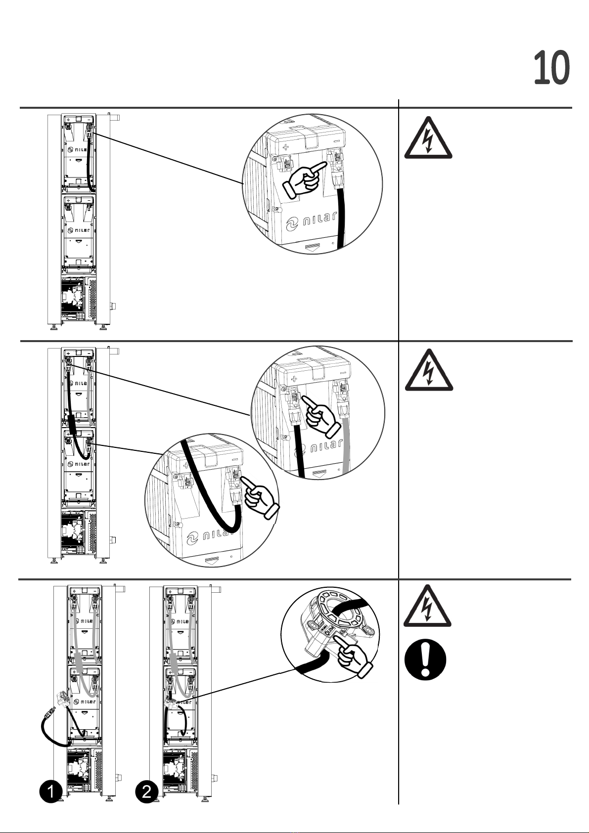
Posive(+)wireofpowercable
connectstotheposive
terminal(+)oftheNilarBMS.
Theprotecveearth(PE)wireof
thepowercableistobeconnec-
tedtotheprotecveearth(PE)
terminaloftheNilarBMS.
10
11
12
Negave(-)wireofpowercable
connectstothenegave
terminal(-)oftheNilarBMS.
CONDUCTUR CROSS‐SECTION
MAX 6 mm2
CONDUCTUR CROSS‐SECTION
MAX 6 mm2
THE POSITIVE (+) WIRE OF
THE INCOMING POWER
CABLES MUST ALWAYS BE
EXTERNALLY PROTECTED
BY A 10A DC‐FUSE
(1000VDC)
CONDUCTUR CROSS‐SECTION
MAX 6 mm2
THE NEGATIVE (‐) WIRE
OF THE INCOMING
POWER CABLES MUST
ALWAYS BE EXTERNALLY
PROTECTED BY A 10A DC‐
FUSE (1000VDC)

14
Placetheinsulaontraysonthe
shelfslotsoftheHomeBox
NEVER INSTALL BATTERY
PACKS WITHOUT INSULATION
TRAYS.
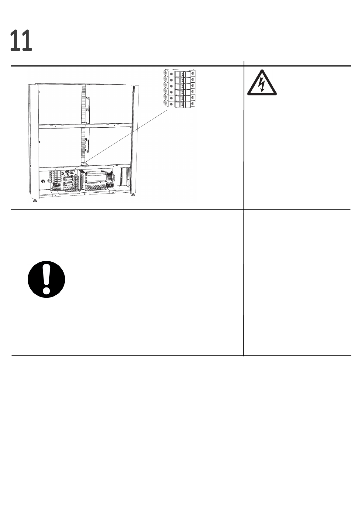
Connectaninternetcabletothe
RJ45portonthebacksideofthe
cabinet.
13
15
FixatetheHomeBoxby
aachingthemounngbrackets
with(2)screwseachontoastab-
lewall.
THE HOME BOX MUST
ALWAYS BE ATTACHED TO A
STABLE WALL. TYPE AND
LENGTH OF SCREWS DEPEND
ON MATERIAL IN WALL AND
THE SCREWS ARE NOT
SUPPLIED WITH NILAR HOME
BOX.

16
17
18
ID‐MARKING IN SHELF SLOT
OF CABINET MUST MATCH ID
‐MARKING ON BATTERY PACK
IT IS RECOMMENDED TO USE
LIFTING AIDS
Fixatethebaerypackstothe
insulaontraywiththescrews.
Repeatforallbaerypacks.
TXD 2
x 2
x 4
Carefullyli/slidethebaery
packsintotheirdedicatedshelf
slots.
REMOVE BOTH LIFTING
STRAPS FROM THE BATTERY
PACKS.
TXD 2
x 4
20
21
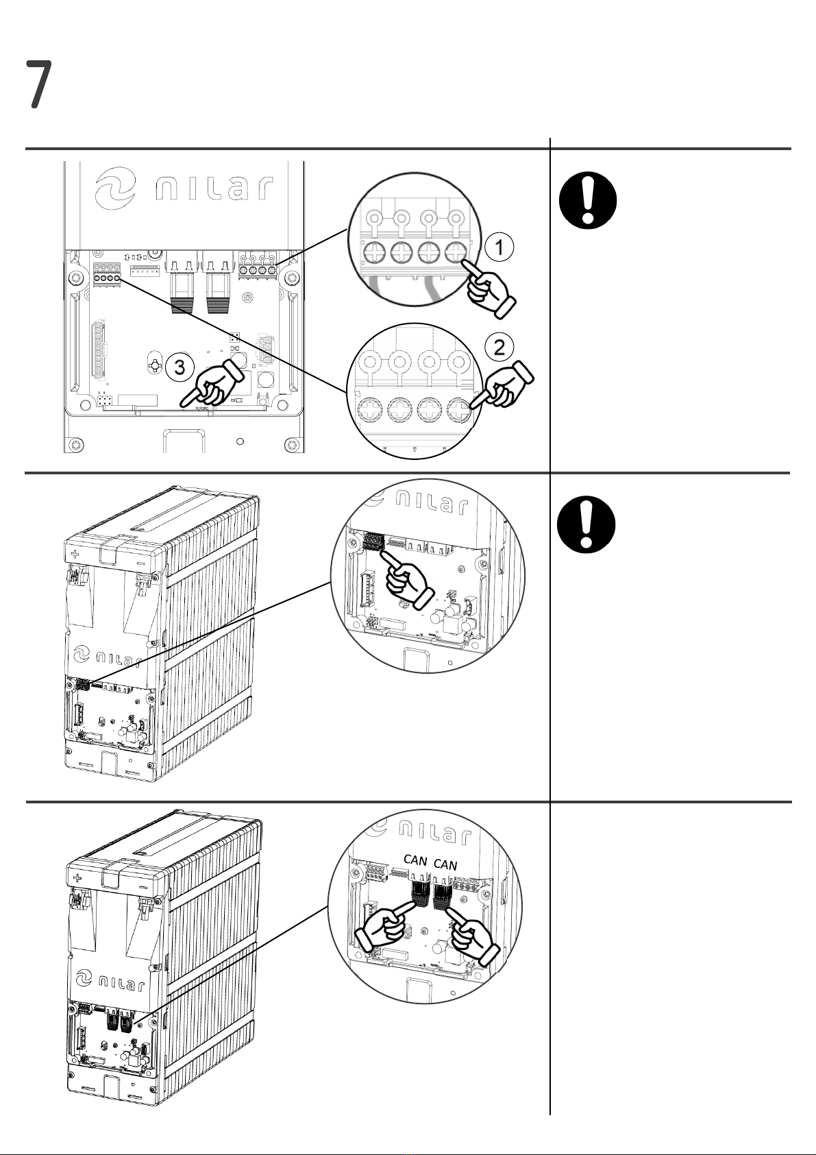
Connectthepre-routed
communicaoncablefromBMS
tobaerypack’A’(RJ45).
Connecttheinterpack
communicaoncablesbetween
baerypack’A’and’B’,
between’B’and’C’(pre-routed)
andbetween’C’and’D’.
Connectthepre-routed
communicaoncablefromESO
tobaerypack’D’.
19
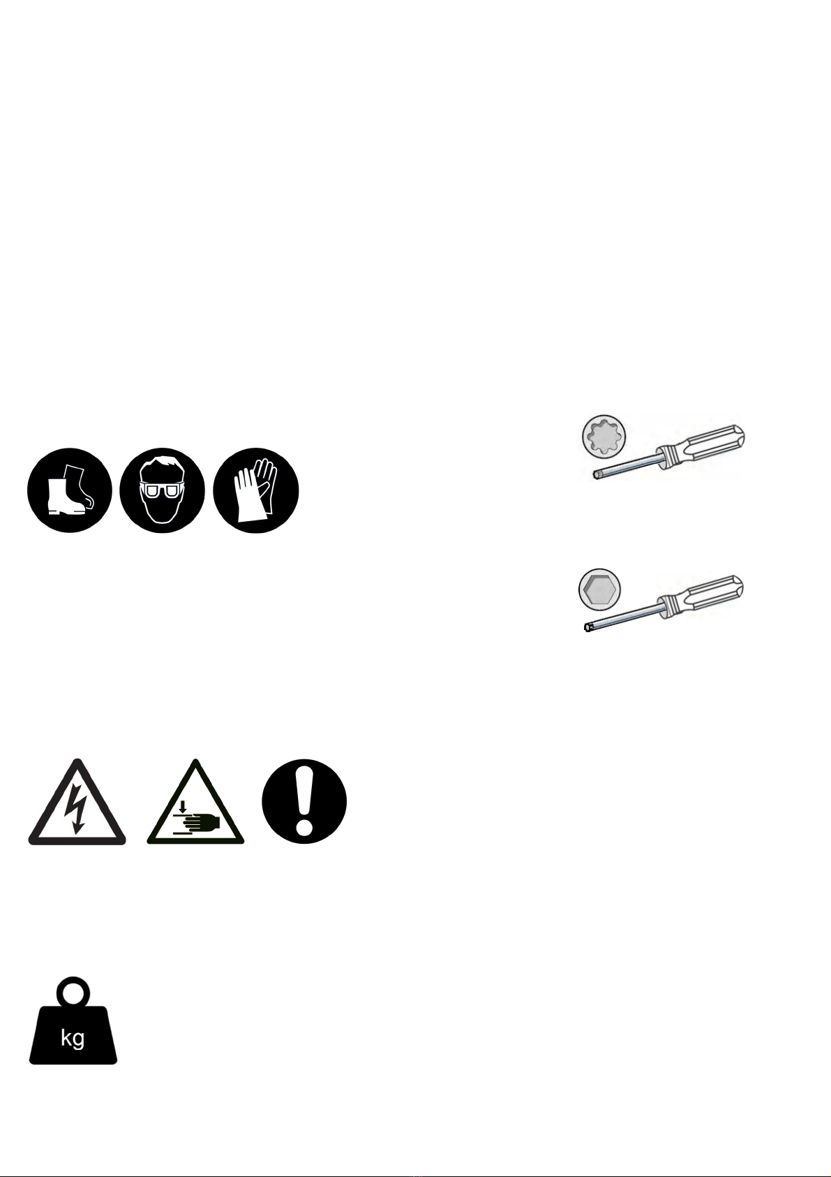
Connectthecurrentsensor
cabletobaerypack’D’.
Makesurethattheclamping
screws/springsforthe24VDC
powersupply①andthe
Currentsensor②arevisibleon
thefrontsideoftheconnectors
andthatthecablesarepoinng
towardsthecableentry③.
BE CAREFUL TO CONNECT
THE IMU CONNECTORS WITH
THE CORRECT ORIENTATION
INSTALL AS DESCRIBED IN
INSTALLATION STEP #19

22
23
24
Connectallthefancablestoall
baerypacks.
Connectthepre-routed24VDC
powersupplycabletoeach
baerypack.
Connecttheambient
temperaturesensorcableto
baerypack’A’.
Installthecoverlidsbackonall
thebaerypacksandcheckthat
allcablesareroutedthroughthe
cableentry.
INSTALL AS DESCRIBED IN
INSTALLATION STEP #19
26
27
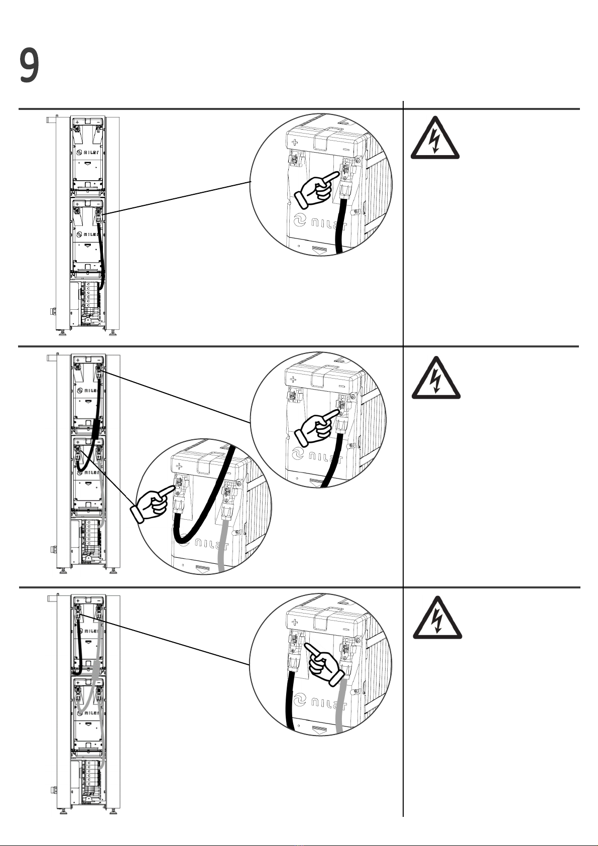
Plugthepre-routedinterpack
cableintotheposive(+)chassis
connectorofbaerypack‘B’.
25
Connecttheposive(+)chassis
connectorofbaerypack‘A’to
thenegave(-)chassis
connectorofbaerypack‘B’by
usingone,ofthetwo,external
interpackpowercables.
Connectthepre-routednegave
(-)powercable(1:A)intothe
negave(-)chassisconnectorof
baerypack‘A’.
DO NOT CONNECT THE
POSITIVE (+) AND THE
NEGATIVE (‐) TERMINAL
ON THE SAME BATTERY
PACK (= SHORT‐CIRCUIT!)
CHECK THAT THE FUSES
ARE NOT ACTIVATED , SE
INSTALLATION STEP #31
29
Plugtheotherendofthe
pre-routedinterpackcableinto
thenegave(-)chassis
connectorofbaerypack‘C’.
Lacethepre-routedposive(+)
powercable(1:D)throughthe
currentsensorandconnectitto
theposive(+)chassis
connectorofbaerypack‘D’.
THE TEXT MARKING “LEM”
OF THE CURRENT SENSOR
MUST POINT TOWARDS THE
POSITIVE (+) CHASSIS
CONNECTOR
28
Connecttheposive(+)chassis
connectorofbaerypack‘C’to
thenegave(-)chassis
connectorofbaerypack‘D’by
usingtheremainingexternal
interpackpowercable.
30
DO NOT CONNECT THE
POSITIVE (+) AND THE
NEGATIVE (‐) TERMINAL
ON THE SAME BATTERY
PACK (= SHORT‐CIRCUIT!)
32
31
ASSEMBLE THE NILAR HOME BOX CABINET IN THE
REVERSE ORDER OF HOW IT IS DESCRIBED IN STEP
2 – 7 AND CONTACT FERROAMP FOR FURTHER
INSTRUCTIONS BEFORE TAKEN INTO OPERATION .
Removetheadhesivetapeover
thefusebox,acvatethefuses
byclosingthehatches.


NilarAB
Stockholmsvägen116B,6tr
SE‐18730Täby,Sweden
This manual suits for next models
1
Table of contents
Other Nilar Batteries Pack manuals


