ET Enterprises HVLAB3000 User manual

ET Enterprises Limited
45 Riverside Way
Uxbridge UB8 2YF
United Kingdom
tel: +44 (0) 1895 200880
fax: +44 (0) 1895 270873
e-mail: [email protected]
web site: www.et-enterprises.com
The company reserves the right to modify these designs and specifications without notice.
Developmental devices are intended for evaluation and no obligation is assumed for future
manufacture. While every effort is made to ensure accuracy of published information the
company cannot be held responsible for errors or consequences arising therefrom.
an ISO 9001 and ISO 14001 registered company
© ET Enterprises Ltd, 2014
ADIT Electron Tubes
300 Crane Street
Sweetwater TX 79556 USA
tel: (325) 235 1418
toll free: (800) 399 4557
fax: (325) 235 2872
e-mail: [email protected]
web site: www.electrontubes.com
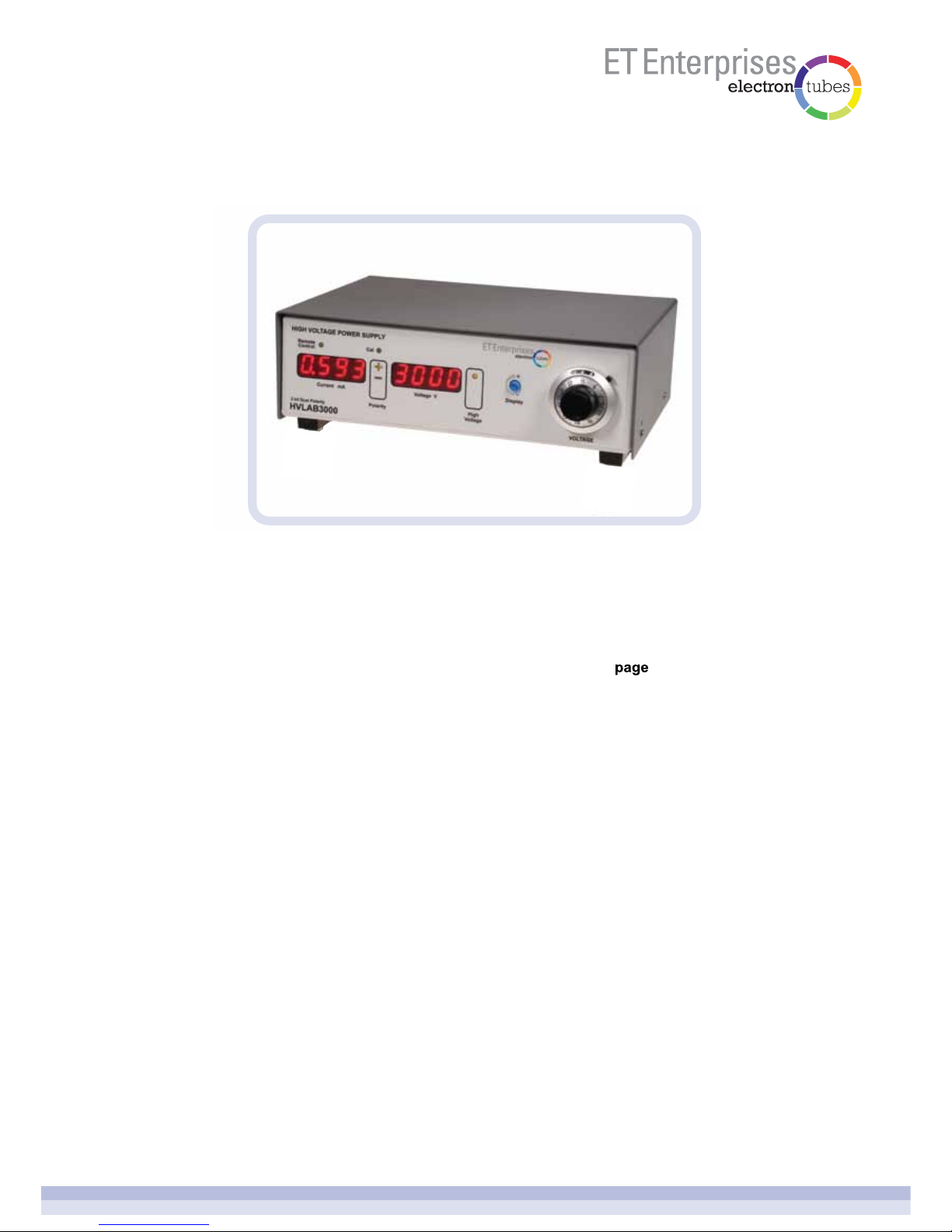
bench-top high voltage power supply
HVLAB3000
user manual
HVLAB3000 Manual Issue 1 20/02/2014
HVLAB3000 bench-top high voltage power supply
page 2 of 14
Introduction
Installing the software
Basic system
Front panel
Rear panel
Using the HVLAB3000
Calibration
1
2
3
4
5
6
7
3
3
3
4
5
6
11
1introduction
2installing the software
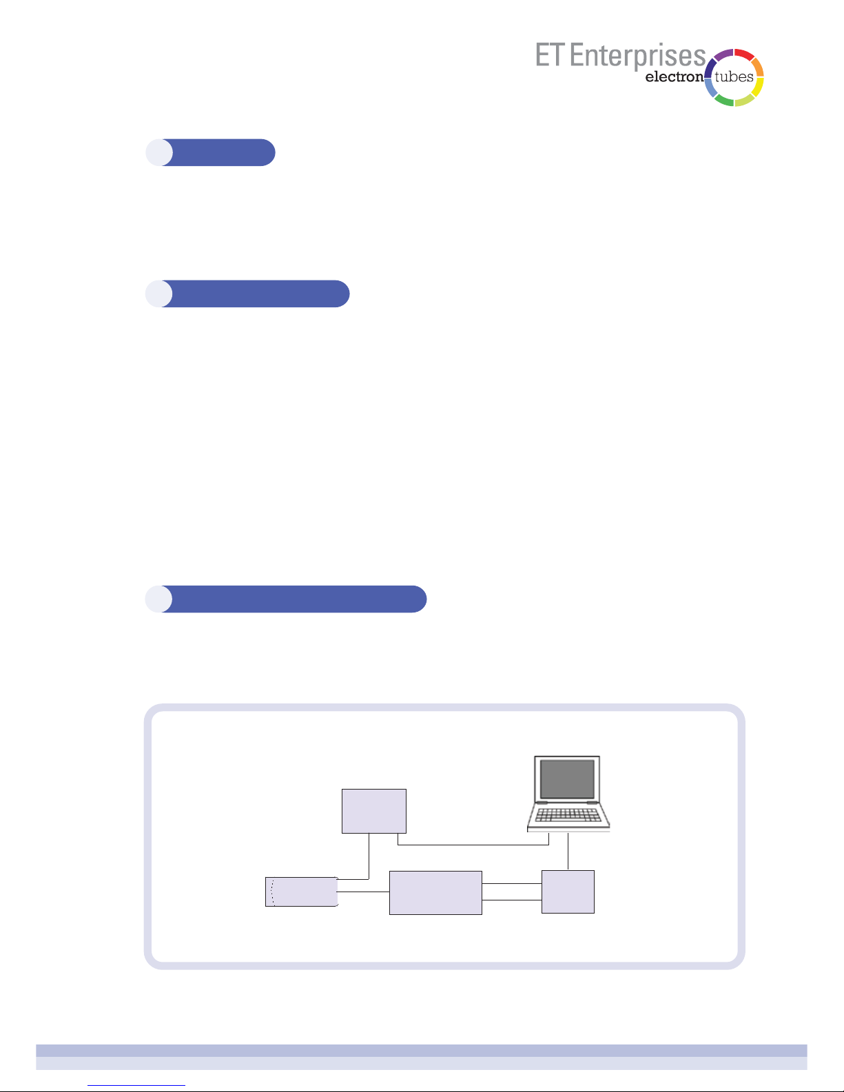
3typical photon counting system
page 3 of 14
The HVLAB3000 is a bench-top high voltage power supply designed for use with
photomultiplier tubes but can be used for other applications requiring a similar specification
supply.
It is only necessary to install the software to use the HVLAB3000 in remote control mode
via USB.
Double click on the HVLAB3000 setup programme HVLAB3000Setup.exe; the setup wizard
will guide you through the setup process.
The software is installed in C:\ETEL\BenchTopHV
Shortcuts to the various applications are installed on your desktop and in the HVLAB3000
program group in your start menu.
To uninstall the software run the uninstall program from the HVLAB3000 program group in
the start menu. All of the installed files will be removed from your system.
The elements of a typical photon counting system are shown in the schematic below. The
AD8 amplifier/discriminator and the MCS-CT3 counter/time are available from
ET Enterprises (see website for details).
PMT anode TTL
+5V
HV USB
HV control
(optional)
HVLAB3000
AD8 MCS-CT3

4front panel
page 4 of 14
1the current display
Shows the approximate output current in mA.
2the voltage display
When the high voltage output is off, the display shows the set voltage. This is the
approximate voltage that will be applied when the output is switched on. When the high
voltage output is switched on, the display shows the measured high voltage.
3the high voltage output on/off button
Press the button to turn the high voltage output on or off. The high voltage ‘on’ LED
indicates when the high voltage output is on.
4the high voltage polarity button
Press the polarity button to change polarity. The button will only operate when the high
voltage output is switched off. The polarity LEDs display the polarity selected. Each
polarity has its own rear panel connector. Only one polarity output may be on at a time.
5high voltage control
Turn the rotary control to adjust the set voltage when the high voltage output is off or
the actual output voltage when the high voltage output is on.
6display brightness adjustment control
Turn the rotary control to adjust the front panel display brightness. It may be useful to
turn the brightness down when using the HVLAB3000 in a dark room.
7 remote control LED
The LED indicates when the HVLAB3000 is controlled remotely using the USB
interface, or the control voltage input.
8cal LED
The calibrate LED indicates when the HVLAB3000 is in calibration mode.

5rear panel
page 5 of 14
1 negative High Voltage output
This output is active when negative polarity is selected, either using the front panel
polarity button or via USB, and the high voltage is switched on.
2 positive High Voltage output
This output is active when positive polarity is selected, either using the front panel
polarity button or via USB, and the high voltage is switched on.
3 power input
Integrated mains input, on/off switch and fuses.
5 positive current limit adjustment
Adjusts the current limit for the positive high voltage output.
6 negative current limit adjustment
Adjusts the current limit for the negative high voltage output.
Limits the adjustment range of the front panel high voltage control. This operates both
positive and negative outputs.
4 high voltage limit adjustment
8 USB connector
The HVLAB3000 can be controlled remotely using USB and the bench-top HV Supply
windows application. In USB remote control mode the voltage output and polarity is
controlled by the windows application and all front panel controls are inactive.
9 auxiliary power outputs
Isolated auxiliary outputs of +5 V, 0 V, -5 V and +12 V, 0 V, -12 V are included to power
electronic modules, such as the range of amplifiers, amplifier/discriminators and
counter/timer modules from ET Enterprises. These are accessed via a 6-pin mini-DIN
socket.
7 remote control voltage input and select switch
Disables the front panel HV rotary control and actives the external voltage control
facility.
Positive
Current
Limit
Negative
Current
Limit
High
Voltage
Limit
8
9
13
45 6 7
2

page 6 of 14
6.2 setting the current limit
6.1 basic operation
6using the HVLAB3000
Connect the mains supply cable and the appropriate high voltage polarity output cable
before switching on the HVLAB3000. The USB control and auxiliary power outputs are
optional and not needed for basic operation.
On switch-on, the HVLAB3000 powers up with the high voltage output off and the high
voltage polarity set to its last setting at switch-off. The high voltage setting is remembered
only by the position of the high voltage adjustment control; the control can be locked to
prevent accidental movement.
Press the Polarity button to set the required polarity and rotate the high voltage adjustment
control to set the desired high voltage. Press the High Voltage button to turn on the high
voltage output. The high voltage may be adjusted with the high voltage output on.
Note: there may be a small offset between the set voltage, shown on the voltage display
with the high voltage off, and the actual measured high voltage with the high voltage
switched on; this is normal.
Note: This setting method is not applicable with very low current loads.
CAUTION: the power input switch must be off before connecting or disconnecting
HV cables.
Each polarity has its own current limit adjustment which is located on the rear panel. The
current limit is independent of the micro-controller.
To set the current limit, find the desired operating voltage for the PMT that you are using
with the current limit adjustment turned fully clockwise (for maximum current). Then
increase the high voltage output by about 100 V. Adjust the current limit anti-clockwise until
the high voltage starts to decrease (the output is now limiting). Then adjust the current limit
clockwise by about half a turn.
If the current limit is set too low, the high voltage output may be noisy as it ‘bounces’ off the
limit.
6.3 setting the high voltage limit
The high voltage limit restricts the range of the front panel high voltage rotary control; it
operates independently of the micro-controller.
With the high voltage output switched off, set the high voltage rotary control fully clockwise
(maximum high voltage). Adjust the rear panel high voltage limit until the front panel voltage
display shows the desired maximum high voltage.
Note: The high voltage limit will need to be re-adjusted if the polarity is changed.

page 7 of 14
Connect the HVLAB3000 to a spare USB port on your computer.
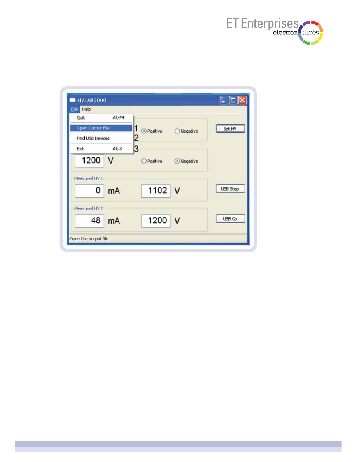
Open the HVLAB3000 Windows application.
6.4.1.1 USB Go
Press the USB Go button to enter USB remote control. The HVLAB3000 front panel
controls will be locked out and the front panel remote control LED will light and the high
voltage will switch on. If the high voltage was on when the USB Go button was pressed, it
will remain on at that voltage. If the HV output was off when the USB Go button was
pressed, the high voltage will switch on at near zero output.
6.4.1.2 USB Stop
Press the USB Stop button to leave USB remote control mode. The high voltage output will
be switched off and the remote control LED will switch off. Normal control will return to the
HVLAB3000 front panel.
6.4.1.3 set HV
Enter the desired high voltage and select the polarity using the radio buttons. The high
voltage will change when the SET HV button is pressed. It may take several seconds for
the high voltage output to settle to its new value.
6.4 remote control
6.4.1 USB control - the Windows application
page 8 of 14
6.4.1.4 measured HV
In USB remote control mode, the measured current and voltage will be displayed and on
the HVLAB3000 front panel.
6.4.1.5 open output file
Opens the output file in Notepad.
6.4.1.6 find USB devices
If the HVLAB3000 is connected to the computer’s USB port after opening the Windows
application, use Find USB Devices to find the HVLAB3000.
6.4.1.7 exit (or quit)
Quits the windows application. The HVLAB3000 exits USB control and the high voltage
output is turned off.

page 9 of 14
6.4.1.8 the output file
The output file is a text file used to record the measured current, measured voltage and
polarity. The file is updated every second when the HVLAB3000 is in USB control mode.
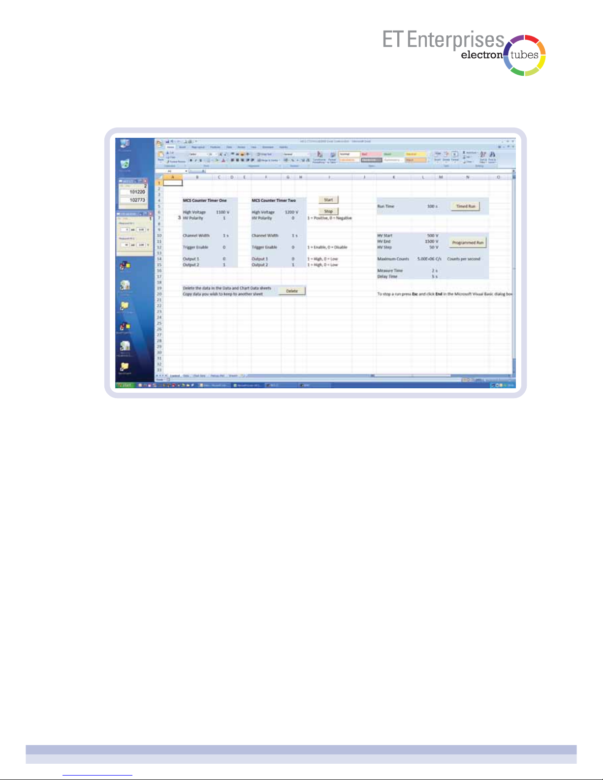
6.4.2 USB control - the Excel spreadsheet
The Excel spreadsheet is a modification of the MCS-CT3 spreadsheet; please see the
MCS-CT3 user manual for more information.
The HVLAB3000 is controlled by the spreadsheet via USB to set the high voltage and
polarity.
1 = +HV; 0 = -HV
Note: macros must be enabled to use the MCS-CT3 HVLAB3000 Excel Control.xlsm
spreadsheet.
page 10 of 14
6.4.2.1 HVLAB3000 windows Excel application
This application starts automatically when you open the MCS-CT3 HVLAB3000 Excel
Control.xlsm spreadsheet. It acts as the interface between Excel and the HVLAB3000
device. The application shows the set high voltage, the polarity and the measured output
current and voltage.
6.4.2.2 MCS-CT3 windows Excel application
This application starts automatically when you open the MCS-CT3 HVLAB3000 Excel
Control.xlsm spreadsheet. It acts as the interface between Excel and the MCS-CT3 USB
device. The application shows the counts for each MCS-CT3 connected.
6.4.2.3 high voltage polarity
Set the required high voltage polarity. The high voltage polarity is actually set when a
sequence of counts is started.
The other controls are explained in the MCS-CT3 user manual.
6.4.2 USB control - the Excel spreadsheet (cont’d.)

page 11 of 14
6.4.2.4 the settings files
The settings file is a user readable text file used in conjunction with the windows Excel
application to control the HVLAB3000.
The MCS-CT3 HVLAB3000 Excel Control.xlsm spreadsheet controls the HVLAB3000 and
the MCS-CT3 by writing to their respective settings files. The HVLAB3000 and the
MCS-CT3 respond when their respective settings file is saved. You can also control the
HVLAB3000 and the MCS-CT3 by modifying their settings file with Notepad.
The settings file is also used to retain the HVLAB3000 and MCS-CT3 settings when the
application is closed or the computer is switched off.
Please see the MCS-CT3 user manual for more information about the MCS-CT3.
6.4.3 external voltage control
When the remote control input switch is in the ON position, the front panel HV control
is disabled and external voltage control is activated, via the adjacent 3.5mm socket. This
mode is indicated by the front panel remote control LED. Selection of the high voltage
polarity and switching the high voltage on or off must still be done using the buttons on the
front panel. A voltage input of 0 to +3V, with reference to system ground, can then be used
to remotely control the high voltage output from 0 to 3000V.
The HVLAB3000 Settings files, Settings_1.txt and Settings_2.txt, are stored in
C:\ETEL\BenchTopHV\.
page 12 of 14
7 calibration
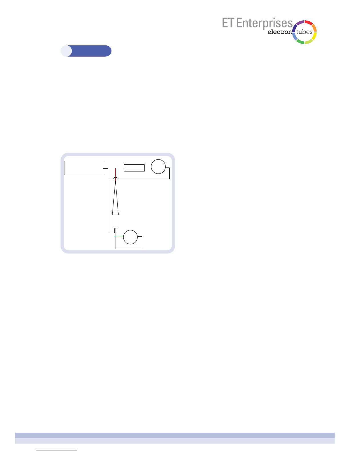
7.2 set-up
Warning: High voltages of over 3000 V will be present during the calibration process.
Note: It is important that the multi-meter connected to the HV Probe is set to a range with a
10 MΩinput impedance, as the high voltage probe is designed to work with a 10 MΩmeter.
7.3 method
7.3.1 before you start
1. Turn the rear panel High Voltage Limit and the Positive and Negative Current Limit
adjustment potentiometers fully clockwise. This will remove the voltage and current
limits.
2. Connect the mains supply and switch on.
7.1 equipment
1. HVLAB3000 to be calibrated.
2. 4.7 MΩthree watt load resistor.
3. 1000:1 high voltage probe, HV Probe (such as Tenma 72-3040; Farnell 4908351).
4. Multi-meter set to measure voltage locked to a d.c. 9.999 V 10 MΩinput impedance
range.
5. Multi-meter set to measure current on a d.c. milli-amp range.
HVLAB3000
HV Probe
0V
HV
V
mA
4.7MΩ
.
.

page 13 of 14
7 calibration (cont’d)
7.3.2 positive output calibration
1. With the high voltage off, adjust the front panel HV control to about 100 V.
2. Set the high voltage polarity to positive using the polarity button.
3. Connect the calibration equipment to the rear panel positive High Voltage output as
shown in the Setup section.
4. Using an appropriately sized tool, press the calibration button which is accessed through
a hole in the right hand side of the HV Supply. The HVLAB3000 will enter calibration
mode, the Cal LED will light and the first calibration voltage will be automatically set.
Use the front panel HV control to adjust the front panel voltage display to agree with the
volt meter reading.
5. Press the calibration button, the HVLAB3000 will now show its current reading. Use the
front panel HV control to adjust the HVLAB3000 current display to agree with the
milli-amp meter reading.
7. Press the calibration button. The next calibration voltage will be set. Repeat steps 4, 5
and 6 for each calibration voltage. The last calibration voltage is about 3100 V.
8. Press the calibration button. The HVLAB3000 will save the calibration factors in internal
memory and exit calibration mode. The Cal LED and the high voltage will switch off.
9. Switch the high voltage on and check that the HVLAB3000 voltage and current readings
agree with the volt meter and the milli-amp meter at various voltages in the range.
10. End of positive calibration.
Note: You may exit the calibration mode at any time by pressing the High Voltage On button.
The HVLAB3000 will exit calibration mode, the Cal LED will go out, the high voltage will
switch off but the previous calibration will be lost and default factors set. To exit the
calibration and save the previous calibration factors switch off the HVLAB3000 while still in
calibration mode. The new calibration factors are only saved at the end of the calibration
procedure.
6. Press the calibration button. The HVLAB3000 will set a voltage as shown on the front
panel voltage display. Use the front panel HV control to adjust the actual output voltage,
shown on the volt meter, until it agrees with the front panel display.

page 14 of 14
7 calibration (cont’d)
7.3.3 negative output calibration
1. With the high voltage off, adjust the front panel HV control to about 100 V.
2. Set the high voltage polarity to negative using the polarity button.
3. Connect the calibration equipment to the rear panel negative High Voltage output as
shown in the Setup section.
4. Using an appropriately sized tool press the calibration button which is accessed through
a hole in the right hand side of the HV Supply. The HVLAB3000 will enter calibration
mode, the Cal LED will light and the first calibration voltage will be automatically set.
Use the front panel HV control to adjust the front panel voltage display to agree with the
volt meter reading.
5. Press the calibration button. The HVLAB3000 will now show its current reading. Use the
front panel HV control to adjust the HVLAB3000 current display to agree with the
milli-amp meter reading.
6. Press the calibration button. The HVLAB3000 will set a voltage as shown on the front
panel voltage display. Use the front panel HV control to adjust the actual output voltage,
shown on the volt meter, until it agrees with the front panel display.
7. Press the calibration button. The next calibration voltage will be set. Repeat steps 4, 5
and 6 for each calibration voltage. The last calibration voltage is about 3100 V.
8. Press the calibration button. The HVLAB3000 will save the calibration factors in
internal memory and exit calibration mode. The Cal LED and the high voltage will switch
off.
9. Switch the high voltage on and check the HVLAB3000 voltage and current readings
agree with the volt meter and the milli-amp meter at various voltages in the range.
10.End of negative calibration.
Note: You may exit the calibration mode at any time by pressing the High Voltage On
button. The HVLAB3000 will exit calibration mode, the Cal LED will go out, the high voltage
will switch off but the previous calibration will be lost and default factors set. To exit the
calibration and save the previous calibration factors switch off the HVLAB3000 while still in
calibration mode. The new calibration factors are only saved at the end of the calibration
procedure.
Table of contents
Popular Power Supply manuals by other brands


Analytic Systems
Analytic Systems PWS610 Series Installation & operation manual

Datamars
Datamars 0.5 J MkII Unigizer user guide

AMX
AMX RDA-PSM Wiring diagram

Kikusui
Kikusui PAD-L III Series Operation manual

NCR
NCR 7761-K120 Kit instructions

SEW-Eurodrive
SEW-Eurodrive MOVITRANS Compact operating instructions


