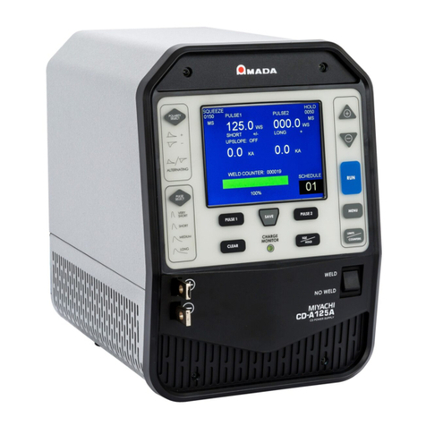
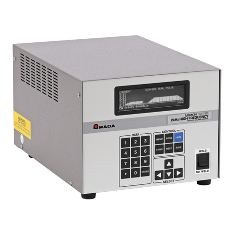
Amada IP-100D User manual

Y02M0821E-04
OPERATION MANUAL
INVERTER WELDING POWER SUPPLY
IP-100D/200D

IP-100D/200D
1
Thank you for purchasing our Inverter Welding Power Supply IP-100D/200D.
・This operation manual explains its method of operation and precautions for use.
・Before using, read this operation manual carefully; after reading, save it in a proper place
where you can easily access.
Contents
1. Special Precautions....................................1-1 to 1-4
2. Features.......................................................2-1
3. Name and Functions of Each Section.......3-1 to 3-6
4. Installation and Connection.......................4-1 to 4-3
5. Basic Operation ..........................................5-1 to 5-12
6. Replacing Battery .......................................6-1
7. Interface.......................................................7-1 to 7-7
8. Timing Chart................................................8-1 to 8-2
9. Troubleshooting .........................................9-1 to 9-3
10. Specifications .............................................10-1 to 10-3
11. External Communication Specifications ..11-1 to 11-7
12. Outline Drawing ..........................................12-1 to 12-2
13. Schedule Data Table...................................13-1 to 13-2

IP-100D/200D
1. Special Precautions
1-1
1. Special Precautions
(1) Safety Precautions
Before using, read "Safety Precautions"
carefully to understand the correct method
of use.
■These precautions are shown for safe use
of our products and for prevention of
damage or injury to operators or others.
Be sure to read each of them, since all of
them are important for safety.
■The meaning of the words and symbols is
as follows.
These symbols denote
"prohibition". They are
warnings about actions
out of the scope of the
warranty of the product.
These symbols denote
actions which operators
must take.
Each symbol with a
triangle denotes that the
content gives notice of
DANGER, WARNING or
CAUTION to the
operator.
Denotes operations and practices that
may imminently result in serious injury
or loss of life if not correctly followed.
Denotes operations and practices that
may result in serious injury or loss of life
if not correctly followed.
Denotes operations and practices that
may result in personal injury or damage
to the equipment if not correctly followed.
Do not touch the interior of the Power Supply unnecessarily
Since very high voltages are applied to the interior of this Power Supply, it is
very dangerous
to touch it unnecessarily. You may touch it only when you
replace the battery. When inspecting the interior of the Power Supply, be sure to
turn off the Main Breaker of the Power Supply. (For details, see 6. Replacing
Battery.)
Never disassemble, repair or modify the Power Supply
These actions can cause electric shock and fire. Do not do anything other than
the maintenance described in the operation manual.
Never burn, destroy, cut, crush or chemically decompose the Power Supply
This product incorporates parts containing gallium arsenide (GaAs).
DANGER
!
W
ARNING
!
CAUTION
!
DANGER
!

IP-100D/200D
1. Special Precautions
1-2
Do not put your hands between the electrodes
When welding, keep your fingers and hands away from the electrodes.
Do not touch any welded part or electrodes during welding and just after
welding finished
The welded part of a workpiece, electrodes and arm are very hot.
Do not touch them; otherwise you may be burnt.
Ground this Power Supply
If the Power Supply is not grounded, you may get an electric shock when fault
occurs, or electricity leaks.
Apply 3-Phase, 180–240
V AC power supply
Application of a voltage out of the specified range can cause fire and electric
shock.
Connect the specified cables securely
Cables of insufficient current capacities and loose connections can cause fire
and electric shock.
Do not damage the power cable and connecting cables
Do not tread on, twist or tense any cable. The power cable and connecting
cables may be broken, and that can cause electric shock and fire. If any part
needs to be repaired or replaced, consult us or your distributor.
Stop the operation if any trouble occurs
Continuous operation after occurrence of a trouble such as burning smell,
abnormal sound, abnormal heat, smoke, etc. can cause electric shock and fire.
If such a trouble occurs, immediately consult us or your distributor.
Persons with pacemakers must stay clear of the welding machine
A person who uses a pacemaker must not approach the welding machine or
walk around the welding shop while the welding machine is in operation, without
being permitted by his/her doctor. The welding machine generates a magnetic
field and has effects on the operation of the pacemaker while it is turned on.
Protective gear must be worn
Put on protective gear such as protective gloves, long-sleeve jacket, leather
apron, etc. Surface flash and expulsion can burn the skin if they touch the skin.
Wear protective glasses
If you look at the surface flash and expulsion directly during welding, your eyes
may be damaged.
WA
RNING
!

IP-100D/200D
1. Special Precautions
1-3
Do not splash water on the Power Supply
Water splashed over the electric parts can cause electric shock
and short
circuits.
Use proper tools (wire strippers, pressure wire connectors, etc) for
termination of the connecting cables
Do not cut the conductor of wire. A flaw on it can cause fire and electric shock.
Install the Power Supply on firm and level surface
If the Power Supply falls or drops, injury may result.
Do not place a water container on the Power Supply
If water spills, insulation will deteriorate, and this may cause electric leak and
fire.
Do not cover the Power Supply with a blanket, cloth, etc.
If such a cover is used, it may be overheated and burn.
Do not use this Power Supply for purposes other than welding
Use of this Power Supply in a manner other than specified can cause electric
shock and fire.
Use ear protectors
Loud noises can damage hearing.
Keep a fire extinguisher nearby
Keep a fire extinguisher in the welding shop in case of fire.
Maintain and inspect the Power Supply periodically
Maintain and inspect the Power Supply periodically, and repair any damage
nearby before starting operation.
CAUTION
!

IP-100D/200D
1. Special Precautions
1-4
(2) Precautions for Handling
■When transporting or moving the Power Supply, do not lay it down. Also, handle
the Power Supply with care so as not to make an impact such as drop on it.
■Install this Welding Power Supply on a firm, level, horizontal surface. If it is
inclined, malfunction may result.
■Do not install this Welding Power Supply in the following:
・Damp places where humidity is higher than 90%,
・Hot or cold places where temperatures are above 45°C or below 0°C,
・Places near a high noise source,
・Places where chemicals are handled,
・Places where water will be condensed,
・Dusty places, and
・Places at an altitude above 1000 meters.
■Clean the exterior of the Welding Power Supply with a soft, dry cloth or one wet
with a little water. If it is very dirty, use diluted neutral detergent or alcohol. Do
not use paint thinner, benzine, etc., since they can discolor or deform the
Welding Power Supply.
■Do not put a screw, a coin, etc., in the Welding Power Supply, since they can
cause a malfunction.
■Operate the Welding Power Supply according to the method described in this
operation manual.
■Operate the switches and buttons carefully by hand. If they are operated roughly
or with the tip of a screwdriver, a pen, etc., this will cause malfunction or
damage.
■The Power Supply is not equipped with auxiliary power such as an outlet for
lighting.
■The cable to supply power, the welding head, and the secondary cable for
connecting the welding head with the Power Supply are separately needed to
use the Power Supply.
■The I/O signal line to start the Power Supply is not attached. Prepare the
crimp-on terminal and line for wiring to the terminal block.
(3) On Disposal
This product incorporates parts containing gallium arsenide (GaAs). At the time of
disposal, separate it from general industrial waste or domestic waste and carry out
the disposal in accordance with applicable laws and regulations.


IP-100D/200D
2. Features
2-1
2. Features
The IP-100D/200D is an inverter type of compact Precise Resistance Welding Power
Supply which realizes excellent weldability and operation, and is provided with Constant
Current Control Function accommodating to various kinds of workpieces.
Sixty-three (63) types of welding schedules can be registered
Once a welding schedule is registered, it can be invoked by one key operation only.
When the welding schedules which will be used frequently are registered, you do not
need to enter the schedules each time when you operate.
Welding schedules can easily be set with four (4) keys
No troublesome operation is requested at all. Setting of the welding schedule is done
by means of four keys only.
Monitor facility is helpful for stable quality control
IP-100D/200D monitors welding current.
When actual welding current is beyond the monitoring range setting, then error signal
will be output to inform the user of occurrence of abnormal welding promptly.
Automatic switching of screen display
Normally, monitor panel displays the settings of welding schedules. However, the
display will automatically be switched to the monitoring values of the current when
welding current flows.
Good-looking and easy-to-see screen display
Because high-intensity LCD (Liquid Crystal Display) is employed, the display can be
seen clearly even in the gloom.
Sheet panel is sufficiently resistive to dust and oil mist
Stain can be removed very easily and therefore clean external view can be
maintained for a long time.
Built-in welding transformer
Permits the small-sized Welding Power Supply.
▽
▽
+ー

IP-100D/200D
3. Name and Functions of Each Section
3-1
3.
Name
and
Functions
of
Each
Section
(1) Front Panel
①LCD Panel
This is the display panel to check the status of operation of IP-100D/200D.
This display appears when [POWER] main circuit breaker is turned on.
LCD Display Panel displays Setting Screen that is used to set each item of the
welding conditions and Monitor Screen that is used to indicate measured values of
the welding current actually flowed. When any one of key is pressed in the Monitor
Screen, the screen will be switched to the Setting Screen.
SQ(×10)
HO
SCHEDULE
W2R2
HEAT2HEAT1
START
READY
WELD
63 49 99 99 49 299
R1 CO
W1
SCHEDULE
R1 W1
999 1000<GO>1000 999
① LCD panel
② Cursor key
③[+]key
④[-]key
⑤ [WELD] key
⑥ [WELD] lamp
⑦ [READY] lamp
⑧ [START] lamp
⑩ Output terminal
bars
⑨ Welding transformer
(a) (b) (c) (d) (e) (f)
(g) (h) (i) ( j)
(k) (l) (m) (n) (o)
(p) (q) (r)
SQ(×10)
HO
W2R2
HEAT2HEAT1
01 10 20 10 20 100
CO
SCHEDULE
R1 W1
100 0600 0800 100
SQ(×10)
HO
W2R2
HEAT2HEAT1
01 10 20 10 20 100
CO
SCHEDULE
R1 W1
100 0598<GO>0796 100
When welding
current flows...
Setting Screen Monitor Screen
When any key is depressed...

IP-100D/200D
3. Name and Functions of Each Section
3-2
(a) SCHEDULE
Sets and indicates the Welding Schedule Numbers. The number of
settings of the welding schedule to be registered is sixty-three (63),
ranging from Nos. 01 to 63.
(b) R1
Sets and indicates the Upslope time (00 to 49
ms) given in the first stage of
welding.
The Upslope time is:
The time from the start of current to the time when the current reaches the
current setting. If set current flows from the start of welding, it may be
resulted in explosion. Welding current is increased gradually in order to
prevent generation of explosion, and this process is called Upslope.
(c) W1
Sets and displays the weld time (00 to 99
ms) in the first stage of welding.
R1 time is included in this weld time.
(d) CO (Cooling time)
Sets and displays the period of time (00 to 99
ms) to cool down the
workpiece after shutting down welding current upon completion of the first
stage welding.
(e) R2
Sets and indicates the Upslope time (00 to 49
ms) given in the second
stage of welding.
(f) W2
Sets and displays the weld time (000 to 299
ms) in the second stage of
welding. R2 time is included in this weld time.
(g) SQ (Squeeze Time)
Sets and indicates Squeeze Time (000 to 999 x 10
ms).
This function is ready when the Software switch (SW5) is set to “1”.
(h) HEAT1
Sets and displays the current in the first stage of welding.
IP-100D: 0100 to 1300
A
IP-200D: 0400 to 2500
A
(i) HEAT2
Sets and displays the current in the second stage of welding.
IP-100D: 0100 to 1300
A
IP-200D: 0400 to 2500
A
(j) HO (Hold time)
Sets and displays the length of time (000 to 999
ms) to hold workpiece after
turning off welding current upon completion of the second stage welding.
This function is ready when the Software switch (SW5) is set to “1”.

IP-100D/200D
3. Name and Functions of Each Section
3-3
(k) R1
On monitor screen, displays the first stage upslope time during which the
welding current actually flowed within R1 time. (If WELD STOP has been
input, the actual weld time is displayed.)
(l) W1
On monitor screen, displays the weld time during which the welding current
actually flowed within W1 time. (If WELD STOP has been input, the actual
weld time is displayed.)
(m) CO
On monitor screen, displays the time during which the welding current
actually flowed within CO time. (If WELD STOP has been input, the actual
cool time is displayed.)
(n) R2
On monitor screen, displays the second stage upslope time during which
the welding current actually flowed within R2 time. (If WELD STOP has
been input, the actual weld time is displayed.)
(o) W2
On monitor screen, displays the weld time during which the welding current
actually flowed within W2 time. (If WELD STOP has been input, the actual
weld time is displayed.)
(p) HEAT1
On monitor screen, displays the measured welding current in the first stage
of welding.
(q) <GO> / <NG> / <**>: Monitor current is average value or
[GO] / [NG] / [**]: Monitor current is peak value (*)
(displayed on the Monitor Screen only)
The Setting Screen is automatically switched to Monitor Screen when
welding is complete. <GO> or [GO] will be displayed if the of actual current
is within the monitoring range set in HEAT1 and HEAT2. On the other hand,
<NG> or [NG] will be displayed if the magnitude of actual current is outside
the monitoring range. (See 5. Basic Operation (1) ○
11 for the monitoring
range.)
If Monitor Upper/Lower Limit is set to one of the followings, < * * > or [**]
will be displayed:
When setting +0% or –0%. (No monitor upper/lower limit)
Both the first and second stage welds are set to 0
ms. (No weld time)
* For selecting average and peak values, see 5. Basic Operation (1) ○
12 .
(r) HEAT2
On monitor screen, displays the measured welding current in the second
stage of welding.

IP-100D/200D
3. Name and Functions of Each Section
3-4
②[Cursor]Keys
Move the cursor ( ) on the Setting Screen. The figures selected by the cursor can
be changed. Furthermore, when this key is pressed during abnormal conditions,
trouble signal output that indicates abnormal condition is turned off.
③[+] Key
Changes the number selected by the cursor. Every time the key is depressed, the
number increases. Furthermore, when this key is pressed during abnormal
conditions, trouble signal output that indicates abnormal conditions is turned off.
④[-] Key
Changes the number selected by the cursor. Every time the key is depressed, the
number decreases. Furthermore, when this key is pressed during abnormal
conditions, trouble signal output that indicates abnormal conditions is turned off.
⑤WELD [WELD] Key
When this key is depressed, the [WELD] lamp located upper left will illuminate to
allow IP-100D/200D to flow welding current (However, when [WELD] (WELD
ON/OFF) of [I/O] connector is in off position, current will not flow). When the key is
pressed for 0.5 or more seconds while [WELD] lamp illuminates, the lamp will be
turned off and IP-100D/200D cannot flow welding current. Furthermore, when this
key is pressed during abnormal conditions, trouble signal output that indicates
abnormal conditions is turned off.
⑥[WELD] Lamp
Lights up when [WELD] key is depressed.
One of the requirements to turn on [READY] lamp.
⑦[READY] Lamp
Lights up when the welding current is ready to flow.
If you want to confirm the operation of the connected equipment without allowing
welding current to go through, be sure to confirm that this lamp extinguishes.
In order for the lamp to illuminate, all of the following conditions must be satisfied:
[WELD] lamp illuminates.
Pins 13 and 14 (WELD ON/OFF) of [I/O] connector, which are located on the
rear panel, are on.
No abnormal condition occurs.
⑧[START] Lamp
Lights up when START signal is input.
⑨Welding Transformer
Inverter transformer is built in.
IP-100D: Maximum output current 1300
A
Rated capacity 1.4
kVA (open-circuit voltage 5.5
V)
IP-200D: Maximum output current 2500
A
Rated capacity 5.3
kVA (open-circuit voltage 8.1
V)
▽
▽
+
ー

IP-100D/200D
3. Name and Functions of Each Section
3-5
⑩Output Terminal Bars
Output terminals of the welding transformer. The upper one is positive and lower
one negative. The diameter of each hole is 8.5 mm. These terminals are
connected to the welding head by the secondary cable.
(2) Rear Panel
⑪[POWER] Main Circuit Breaker
Turns on and off IP-100D/200D. When the handle is pulled up to ON position,
power supply is applied to its main body; pushed down to OFF position, power
supply is disconnected.
⑫[TEST] Button
Checks for inspection whether the [POWER] main circuit breaker functions
normally. Check that when the button is pressed with a rod, the handle turns
down to the half way between ON and OFF positions to turn off IP-100D/200D.
After operation of [TEST] button, push down the handle to OFF position first,
then, pull up to ON position.
CAUTION
Do not use the [TEST] button to turn off IP-100D/200D after completion of work.
ON
23
25
27
29
31
33
35
37
39
21
⑲
⑰
⑮
⑬
⑪
⑨
⑦
⑤
③
①
38
36
34
32
30
28
26
24
22
⑳
⑱
⑯
⑭
⑫
⑩
⑧
⑥
④
②
ON
⑯ I/O cable inlet
⑯ I/O terminal
cover
⑱ Vent
⑮ Power cable
inlet
⑬ I/O terminals
With I/O terminal cover removed
⑰ Grounding
terminal
⑪ [POWER] main
circuit breaker
⑫ [TEST] button

IP-100D/200D
3. Name and Functions of Each Section
3-6
⑬I/O Terminals
Used to connect IP-100D/200D and external equipment. Connect signal wires
as necessary.
⑭I/O Cable Inlet
Pass the signal cable through this inlet and connect the cable to the I/O cable
terminals.
⑮Power Cable Inlet
Pass the Power Cable through this inlet and connect the cable to Power Cable
Terminals.
Recommended Cable Spec.
Power Cable
Rated voltage 300
V min.
Number of cores 4
Cross section 2
mm2min.
⑯I/O Terminal Cover
Covers I/O terminals. Remove when connecting I/Os.
⑰Grounding Terminal
For grounding. This is mounted behind the cover. Connect the grounding wire
when connecting the power cable to the [POWER] main circuit breaker.
⑱Vent
Cooling air for the interior of IP-100D/200D is sucked in through this vent.

IP-100D/200D
4. Installation and Connection
4-1
4. Installation and Connection
(1) Installation
Install the Power Supply in the following places. (See 1. Special Precautions for
details.)
Slits are provided on right, rear sides and bottom of IP-100D/200D for higher heat
radiation efficiency. Install this Power Supply with a clearance of at least 10
cm from
the side wall to extract the full performance.
Places containing less steam, humidity and dust.
Well-ventilated places.
Places where no chemicals are handled.
Firm and horizontal surface.
Places where it is not extremely hot or cold.
Places where there is no splashed water.
SQ(×10)
HO
SCHEDULE
W2R2
HEAT2HEAT1
START
READY
WELD
63 49 99 99 49 299
R1 CO
W1
R1 W1
999 1000<GO>1000 999
SQ(×10)
HO
HEAT2HEAT1
chemicals
Dust
10
㎝min.
Dirt
Install on a firm,
horizontal surface
Hot
Cold
10
㎝min.
Condensation

IP-100D/200D
4. Installation and Connection
4-2
IP-100D installation clearance
IP-200D installation clearance
(2) Connection
Connect IP-100D/200D to the welding head as shown below:
If the secondary cable is too long and thin, a sufficient welding current may not flow.
Airflow
Airflow
Airflow
Front Rear
10cm minimum 10cm minimum
Intake
Airflow
Front Rear
Airflow
10cm minimum
Intake
10cm minimum10cm minimum
Airflow
Airflow
Secondary
cable
+
-
Welding
head
Start cable
Power cable
Connect to Ter-
minals 3 and 4
on I/O terminals.
R
S
T
IP-100D
or
IP-200D
E

IP-100D/200D
4. Installation and Connection
4-3
When finishing connection to the welding head, connect the power cable to
IP-100D/200D (see drawing below).
①Remove the cover for the [POWER] main circuit breaker on the rear panel.
②Connect the power cable to the [POWER] main circuit breaker.
③Connect the grounding wire to the grounding terminal.
④Pass the power cable through the power cable inlet, and re-mount the cover.
⑤Connect the other side of the power cable to the breaker on your switchboard.
Recommended breaker is as follows:
IP-100D: 5
A
IP-200D: 15
A
OFF
Connect green-
yellow striped
wire to ground
-
ing terminal.

IP-100D/200D
5. Basic Operation
5-1
5. Basic Operation
CAUTION
Before operation, check that the display screen and lamps are turned on
normally and the fan motor is operated.
(1) Welding Schedule Setting
ATTENTION
Programming is inhibited if Terminals 15 and 18 of I/O terminals are shorted,
and welding schedule cannot be set.
Open the circuit between Terminals 15 and 18 to set the welding schedules.
①Setting Welding Schedule Number
Press [Cursor] to move the cursor ( ) to SCHEDULE . Select Welding
Schedule No. (one of 1 to 63) with [+] and [-] keys.
i) When SQ and HOLD functions are not selected
(When Software switch “SW5” is set to 0)
ii) When SQ and HOLD functions are selected
(When Software switch “SW5” is set to 1)
②Setting SQ Time
Press [Cursor] to move the cursor to SQ (x10) . Set Squeeze Time with [+] and
[-] keys. Ten times the displayed figure is set to Squeeze Time.
This function is ready when the Software switch (SW5) is set to “1”.
【Schedule Setting Screen】
Move with
▽
△
SQ(×10)
HO
W2R2
HEAT2HEAT1
01 49 99 99 49 299
CO
SCHEDULE
R1
W1
1000 1000
Move with
▽
△
SQ(×10)
HO
W2R2
HEAT2HEAT1
01 49 99 99 49 299
CO
SCHEDULE
R1
W1
999 1000 1000 999

IP-100D/200D
5. Basic Operation
5-2
③Setting RISE 1 Time
Press [Cursor] to move the cursor to R1 . Press [+] and [-] to set RISE 1 Time.
④Setting WELD 1 Time
Press [Cursor] to move the cursor to W1 . Press [+] and [-] to set the first stage
Weld Time.
ATTENTION
WELD Time includes RISE Time. Set these times as follows:
RISE 1 ≦WELD 1 and RISE 2 ≦WELD 2
Any other settings are prohibited because no proper welding can be expected.
⑤Setting COOL Time
Press [Cursor] to move the cursor to CO . Press [+] and [-] to set COOL.
⑥Setting RISE 2 Time
Press [Cursor] to move the cursor to R2 . Press [+] and [-] to set RISE 2.
⑦Setting WELD 2 Time
Press [Cursor] to move the cursor to W2 . Press [+] and [-] to set the second
stage Weld Time.
⑧Setting HOLD Time
Press [Cursor] to move the cursor to HO . Press [+] and [-] to set the Hold Time.
This function is ready when the Software switch (SW5) is set to “1”.
⑨Setting HEAT 1 Current
Press [Cursor] to move the cursor to HEAT1 . Press [+] and [-] to set the first
stage Welding Current.
⑩Setting HEAT 2 Current
Press [Cursor] to move the cursor to HEAT2 . Press [+] and [-] to set the second
stage Welding Current.
RISE1
Time
WELD1 Time
COOL
Time
Welding
Current
Set as
RISE ≦ W E L D
WELD2 Time
SQ
Time RISE2
Time
HOLD
Time
()

IP-100D/200D
5. Basic Operation
5-3
⑪Setting the Monitoring Range and the End Signal Output Time of Monitor
Function
IP-100D/200D monitors the difference between the current values set in ○
9and
○
10 , and the actual current. Error signal is output if the difference exceeds the
monitoring range (tolerance). Although the monitoring range is factory set to ±0%
at the time of shipment from the factory, it can be changed by the unit of 1% in the
range of +01 – +49% and -01 – -49% by following the procedures described
below.
i) Press both cursor keys
simultaneously
for at least 0.5 seconds.
ii) When the screen appears
on the LCD Panel as
shown, move the cursor
with [Cursor] to the figures
below MON.
iii) Change the monitoring range with [+] and [-] keys.
SCHEDULE Selects Schedule No.
1:-**% Sets the upper limit of the first stage monitor current for each
Schedule No.
1:+**% Sets the lower limit of the first stage monitor current for each
Schedule No.
2:-**% Sets the upper limit of the second stage monitor current for
each Schedule No.
2:+**% Sets the lower limit of the second stage monitor current for
each Schedule No.
NB: If all settings are set to 00%, upper/lower judgment is not made.
iv) End signal output time (ED)
Sets the output time of the [END] signal. (Common to all schedules.)
The setting range is 010 to 200
ms. It can be set by the unit of 10
ms.
The initial setting is 200
ms.
If 0ms is set, “ED=+STms” is displayed. The [END] signal is kept outputting
while the [START] signal is input.
v) Press both cursor keys simultaneously for at least 0.5 seconds
again to return to Schedule setting screen.
△
▽
-+
START
READY WELD
Simultaneously
【Monitoring Range Setting Screen】
SQ(×10)
HO
W2R2
HEAT2HEAT1
63 MON. 1:-49% +49%
CO
SCHEDULE
R1
W1
ED=200ms 2:-49% +49%
Monitoring range

IP-100D/200D
5. Basic Operation
5-4
⑫Setting Serial Communication Condition and Software Switch
By changing the setting of Serial Communication Condition and Software Switch,
function of IP-100D/200D can be altered. Change the function according to the
following procedures.
i) While pressing [Cursor] key , turn on [POWER] main circuit breaker.
ii) When the screen appears on the LCD panel as shown, move the cursor with
[Cursor]. When this screen appears, Start is not accepted. Also, even when
any key is pressed, the screen will not change.
iii) Press [+] or [-] key to set numerical value.
Setting Function
ID # 01–31 Sets Device # of RS-485 communication. (See 11.
External Communication Specifications.)
SPEED
9.6 kbps
19.2 kbps
38.4 kbps
Sets baud rate. Select one of three baud rates.
SW0
Sets start-input stabilize time. (See 8. Timing
Chart.)
0 Weld sequence starts 20
ms after Start Signal input.
1 Weld sequence starts 5
ms after Start Signal input.
2 Weld sequence starts 1
ms after Start Signal input.
SW1
Selects parity check. (See 7. Interface (4).)
0 No parity check.
1 Odd parity check.
ON
While pressing ,…Turn on [POWER]
main circuit breaker
△
▽
-+
WELD
START
READY
SQ(×10) HO
W2R2
HEAT2HEAT1
ID #01 SW01234567
CO
SCHEDULE R1 W1
SPEED 19.2k 00000000
This manual suits for next models
1
Table of contents
Other Amada Power Supply manuals

Amada
Amada PULSETIG MAWA-050A User manual

Amada
Amada IP-500A User manual

Amada
Amada MIH-200A User manual

Amada
Amada S-2200CA User manual

Amada
Amada HF2 User manual

Amada
Amada IP-400B User manual

Amada
Amada 125DP User manual

Amada
Amada IS-800CR User manual

Amada
Amada CD-A Series User manual

Amada
Amada UNIFLOW UF-R4000A User manual
Popular Power Supply manuals by other brands

NETGEAR
NETGEAR APS135W - ProSafe Auxillary Power Supply install guide

ENERMAX
ENERMAX Cyberbron II user manual

ENERMAX
ENERMAX MODU87+ EMG500AWT user manual

Vanderbilt
Vanderbilt SPC4 Series Installation & configuration manual

CJG
CJG PA5W060-0120500-ZU quick start guide

Datamars
Datamars 0.5 J MkII Unigizer user guide