Ross DFR-8104A User manual

Ross Video Limited
DFR-8104A(-C)
Digital Products Frame and Power Supply (PS-8102)
User Manual

DFR-8104A(-C) •Digital Products Frame and Power Supply (PS-8102) User Manual
• Ross Part Number: 8104ADR-004-03
• Release Date: June 16, 2011. Printed in Canada.
The information contained in this manual is subject to change without notice or obligation.
Copyright
© 2011 Ross Video Limited. All rights reserved.
Contents of this publication may not be reproduced in any form without the written permission of
Ross Video Limited. Reproduction or reverse engineering of copyrighted software is prohibited.
Patents
This product is protected by the following US Patents: 4,205,346; 5,115,314; 5,280,346;
5,561,404; 7,034,886; 7,508,455; 7,602,446; 7,834,886; 7,914,332. This product is protected by
the following Canadian Patents: 2039277; 1237518; 1127289. Other patents pending.
Notice
The material in this manual is furnished for informational use only. It is subject to change without
notice and should not be construed as commitment by Ross Video Limited. Ross Video Limited
assumes no responsibility or liability for errors or inaccuracies that may appear in this manual.
Trademarks
• is a registered trademark of Ross Video Limited.
• Ross, ROSS, ROSS®are registered trademarks of Ross Video Limited.
• Leitch® is a registered trademark of Leitch Technologies Corp.
• All other product names and any registered and unregistered trademarks mentioned in
this guide are used for identification purposes only and remain the exclusive property of
their respective owners.

Important Regulatory and Safety Notices
Before using this product and any associated equipment, refer to the “Important Safety
Instructions” listed below to avoid personnel injury and to prevent product damage.
Products may require specific equipment, and/or installation procedures to be carried out to
satisfy certain regulatory compliance requirements. Notices have been included in this
publication to call attention to these specific requirements.
Symbol Meanings
Important Safety Instructions
1. Read these instructions
2. Follow all instructions and heed all warnings.
3. Refer all servicing to qualified service personnel.
4. The equipment’s AC appliance inlets are the means to disconnect the product from the
AC Mains and must remain readily operable for this purpose.
5. Parts of the equipment’s power supplies can still present a safety hazard even with the
product is in the “OFF” state. To avoid the risk of electrical shock and to completely
disconnect the apparatus from the AC Mains, remove all power supply cords from the
product’s AC appliance inlets prior to servicing.
The exclamation point within an equilateral triangle is intended to alert the user to the
presence of important operating and maintenance (servicing) instructions in the
literature accompanying the product. Failure to heed this information may present a
risk of damage or injury to persons or equipment.
Warning — The symbol with the word “Warning” within the equipment manual
indicates a potentially hazardous situation, which if not avoided, could result in death
or serious injury.
Caution — The symbol with the word “Caution” within the equipment manual
indicates a potentially hazardous situation, which if not avoided, may result in minor
or moderate injury. It may also be used to alert against unsafe practices.
Notice — The symbol with the word “Notice” within the equipment manual indicates
a situation, which if not avoided, may result in major or minor equipment damage or a
situation, which could place the equipment in a non-compliant operating state.
Warning Hazardous Voltages — The lightning flash with arrowhead symbol
within an equilateral triangle is intended to alert the user to the presence of
uninsulated “dangerous voltage” within the product’s enclosure that may be of
sufficient magnitude to constitute a risk of shock to persons.
ESD Susceptibility — This symbol is used to alert the user that an electrical or
electronic device or assembly is susceptible to damage from an ESD event.

6. The product chassis is to be rack mounted only. To ensure safe operation and maintain
long-term system reliability, proper installation requires that the front and back area of
the chassis remain clear of obstructions so as not to restrict airflow.
EMC Notices
United States of America
FCC Part 15
This equipment has been tested and found to comply with the limits for a class A Digital device,
pursuant to part 15 of the FCC Rules. These limits are designed to provide reasonable protection
against harmful interference when the equipment is operated in a commercial environment. This
equipment generates, uses, and can radiate radio frequency energy and, if not installed and used
in accordance with the instruction manual, may cause harmful interference to radio
communications. Operation of this equipment in a residential area is likely to cause harmful
interference in which case the user will be required to correct the interference at his own expense.
CANADA
This Class “A” digital apparatus complies with Canadian ICES-003.
Cet appariel numerique de la classe “A” est conforme a la norme NMB-003 du Canada.
EUROPE
This equipment is in compliance with the essential requirements and other relevant provisions of
CE Directive 93/68/EEC.
INTERNATIONAL
This equipment has been tested to CISPR 22:1997 along with amendments A1:2000 and
A2:2002, and found to comply with the limits for a Class A Digital device.
Maintenance/User Serviceable Parts
Routine maintenance to this RossGear product is not required. This product contains no user
serviceable parts. If the module does not appear to be working properly, please contact Technical
Support using the numbers listed under the “Contact Us” section on the last page of this manual.
All RossGear products are covered by a generous 5-year warranty and will be repaired without
charge for materials or labor within this period. See the “Warranty and Repair Policy” section in
this manual for details.
Indoor Use: Warning — To reduce the risk of fire or electric shock, do not
expose this apparatus to rain or moisture.
Notice — Changes or modifications to this equipment not expressly approved by
Ross Video Limited could void the user’s authority to operate this equipment.
Notice — This is a Class A product. In domestic environments, this product may
cause radio interference, in which case the user may have to take adequate
measures.

Environmental Information
The equipment that you purchased required the extraction and use of natural
resources for its production. It may contain hazardous substances that could
impact health and the environment.
To avoid the potential release of those substances into the environment and to diminish the need
for the extraction of natural resources, Ross Video encourages you to use the appropriate
take-back systems. These systems will reuse or recycle most of the materials from your
end-of-life equipment in an environmentally friendly and health conscious manner.
The crossed-out wheeled bin symbol invites you to use these systems.
If you need more information on the collection, reuse, and recycling systems, please contact your
local or regional waste administration. You can also contact Ross Video for more information on
the environmental performances of our products.

Company Address
Ross Video Limited
8 John Street
Iroquois, Ontario
Canada, K0E 1K0
Ross Video Incorporated
P.O. Box 880
Ogdensburg, New York
USA 13669-0880
General Business Office: (+1) 613 •652 •4886
Fax: (+1) 613 •652 •4425
Technical Support: (+1) 613 •652 •4886
After Hours Emergency: (+1) 613 •349 •0006
E-mail (Technical Support): techsupport@rossvideo.com
Website: http://www.rossvideo.com

DFR-8104A(-C) User Manual (Iss. 03) Contents • i
Contents
Introduction 1
Overview.............................................................................................................................. 1-2
Features.................................................................................................................. 1-2
Documentation Terms and Conventions.............................................................................. 1-3
Installation 2
Before You Begin ................................................................................................................2-2
Static Discharge..................................................................................................... 2-2
Unpacking.............................................................................................................. 2-2
Installing the DFR-8104A(-C)............................................................................................. 2-3
Mechanical Overview............................................................................................ 2-3
Power Supply (PS-8102) and Power Cable........................................................... 2-3
Fault Reporting...................................................................................................... 2-4
Improving Performance......................................................................................... 2-4
Ventilation and Cooling ........................................................................................ 2-4
Cabling for the DFR-8104A(-C).......................................................................................... 2-5
Cabling Overview.................................................................................................. 2-5
Optional Field Upgrade Kits 3
CFM-8104A Cooling Fan Overview ................................................................................... 3-2
Installing the CFM-8104A .................................................................................... 3-2
FSB-7110 Rear Support Bars and Brackets......................................................................... 3-3
Specifications 4
Technical Specifications ...................................................................................................... 4-2
Service Information 5
Troubleshooting Checklist................................................................................................... 5-2
Warranty and Repair Policy................................................................................................. 5-3

ii • Contents DFR-8104A(-C) User Manual (Iss. 03)

DFR-8104A(-C) User Manual (Iss. 03) Introduction • 1–1
Introduction
In This Chapter
This chapter contains the following sections:
• Overview
• Documentation Terms and Conventions
A Word of Thanks
Congratulations on choosing an RossGear DFR-8104A(-C) Digital Products Frame and Power
Supply. Your DFR-8104A(-C) is part of a full line of Digital Products within the RossGear
Terminal Equipment family of products, backed by Ross Video's experience in engineering and
design expertise since 1974.
You will be pleased at how easily your new DFR-8104A(-C) fits into your overall working
environment. Equally pleasing is the product quality, reliability and functionality. Thank you for
joining the group of worldwide satisfied Ross Video customers!
Should you have a question pertaining to the installation or operation of your DFR-8104A(-C),
please contact us at the numbers listed on the back cover of this manual. Our technical support
staff is always available for consultation, training, or service.

1–2 • Introduction DFR-8104A(-C) User Manual (Iss. 03)
Overview
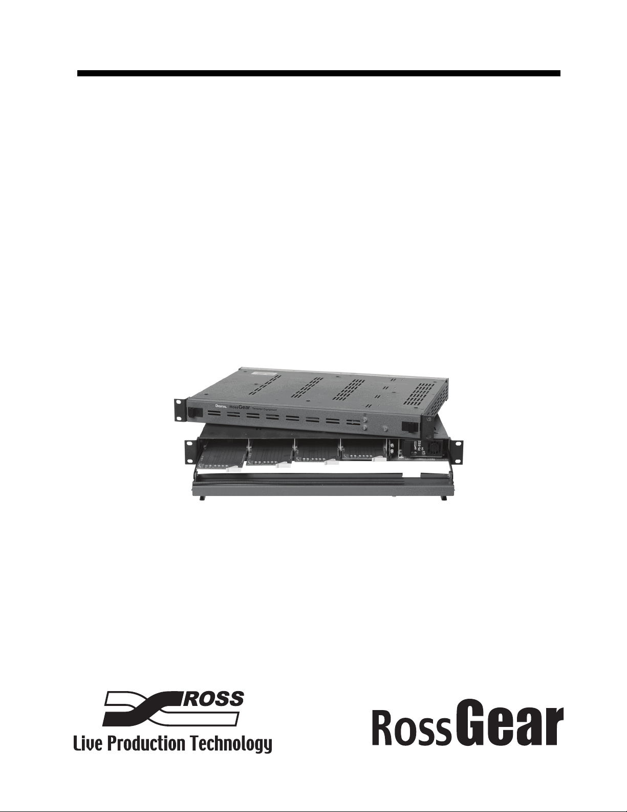
The DFR-8104A(-C) Digital Products Frame accommodates up to four Ross 8000 series
Distribution Products or four Leitch 6800 series video products. For high power consumption
requirements, the DFR-8104A can be field upgraded with the CFM-8104A Cooling Fan Module,
which is mounted in a slot between the power supply and module slot number four. Alternatively,
the DFR-8104A-C comes direct from the factory with the cooling fan option already installed.
The DFR-8104A(-C) design offers several key features such as; heavy-duty door hinges, durable
powder-coat paint finish, and a specially designed top cover to enable frame stacking in high
density environments.
The DFR-8104A(-C) carries forward the heritage of our past digital frames by featuring our
unique Master Reference Input, which accepts one external analog color black signal that is
distributed to all modules. The frame also employs rugged aluminum construction, which
provides superb heat dissipation, as well as the use of the highest quality connectors throughout
the product.
The PS-8102 universal power supply is a power factor corrected supply that will accommodate
all world standards (100-240 volts) with up to 80 Watts of module power. Of special note is that
the PS-8102 has the ability to sustain a 100ms input voltage loss, or glitch, while maintaining a
full power output. This is of great importance in areas where incoming power may not be clean.
Features
The following features make the DFR-8104A(-C) one of the finest digital products frames on the
market today:
• Each frame accommodates four modules in 1 RU
• Heavy duty door hinges
• Durable powder-coat paint finish
• Aluminum construction for increased heat dissipation and weight reduction
• Master Reference Input feeds all module slots
• Power Switch is accessible from front of the rack frame
• Universal Power Supply (PS-8102) for all world standards (100-240 volts)
• PS-8102 sustains a 100ms incoming power glitch while maintaining full output power
• Power factor corrected supply with power fail detection circuit
• PowerLock cord retainer mechanism guards against accidental power loss
• Optional Cooling Fan Module for increased ventilation
• Fan Fail and Error Indicator LED's on front of the frame (available with optional Cooling
Fan Module)
• Optional Extender Board Module for servicing
• Optional Cable Support Bracket
• Optional Frame Support Brackets
• 5-year transferable warranty
• Also accepts Leitch 6800 series video products
Note — It is recommended, for long-term reliability and increased product life span,
that total dissipation of all modules installed in a DFR-8104A(-C) 1RU frame should
not exceed 16 Watts total without the use of the Cooling Fan Module. Refer to the
section “Ventilation and Cooling” on page 2-4 for details.

DFR-8104A(-C) User Manual (Iss. 03) Introduction • 1–3
Documentation Terms and Conventions
The following terms and conventions are used throughout this manual:
•“Frame” refers to the DFR-8104A and DFR-8104A-C frames that house the cards.
•“DFR-8104A” refers to the frame without the CFM-8104A Cooling Fan Module.
•“DFR-8104A-C” refers to the frame with the CFM-8104A Cooling Fan Module.
•“DFR-8104A(-C)” refers to all versions of the frame unless otherwise noted.
•“Operator” and “User” refer to the person who uses DFR-8104A(-C).
•“Board”, and “Card” refer to RossGear terminal device(s) within the frame, including
all components and switches.
•“System” and “Video system” refer to the mix of interconnected production and terminal
equipment in your environment.
• The “Operating Tips” and “Note” boxes are used throughout this manual to provide
additional user information.

1–4 • Introduction DFR-8104A(-C) User Manual (Iss. 03)

2–2 • Installation DFR-8104A(-C) User Manual (Iss. 03)
Before You Begin
Review the following information before proceeding with the instructions in this chapter.
Static Discharge
Throughout this chapter, please heed the following cautionary note:
Unpacking
Unpack each DFR-8104A(-C) you received from the shipping container and ensure that all items
are included. If any items are missing or damaged, contact your sales representative or Ross
Video directly.
ESD Susceptibility — Static discharge can cause serious damage to sensitive
semiconductor devices. Avoid handling circuit boards in high static environments such as
carpeted areas and when synthetic fiber clothing is worn. Always exercise proper grounding
precautions when working on circuit boards and related equipment.

DFR-8104A(-C) User Manual (Iss. 03) Installation • 2–3
Installing the DFR-8104A(-C)
This section outlines how to install the DFR-8104A(-C).
Mechanical Overview
The frame mounts in the rack cabinet by means of four rack screws fastened through the front
mounting flanges. This should normally be sufficient to carry the load, including the weight of
accompanying cables. However, in certain applications such as mobile truck installations, it may
be desirable to also support the rear of the frame. Ross Video has specifically engineered the
optional FSB-7110 Rear Support Bars and Brackets to compensate for extra load stress. Refer to
the section “FSB-7110 Rear Support Bars and Brackets” on page 3-3 for detailed installation
instructions.
Power Supply (PS-8102) and Power Cable
The DFR-8104A(-C) comes standard with one PS-8102 power supply and one power cable.
Of great importance to the user who may have unstable or unpredictable facility power, is the
ability of the PS-8102 to withstand input power glitches of up to 100ms in length, while still
providing uninterrupted power to the modules in the frame. This is an essential feature for
applications such as program feeds, live event feeds, or wherever a robust signal system is
required.
The PS-8102 is a power factor corrected supply, capable of working with all world standards
(100-240V). The supply has an error detection circuit that will indicate the following conditions:
Table 2.1 Power Supply Status LED Descriptions
Location Color Description
Power Supply
Green
When lit green, this LED indicates that the PS-8102 is operating
normally. Normal conditions load: 2W to 40W (recommended
load >2W).
Note:
• the PS-8102 does not detect when the negative rail is faulty.
• that the PS-8102 may not detect when the fuse on the positive
rail is blown (in the case of a Dual Supply).
Flashing
Reda
a. If the power is turned on with a “short” condition in the frame or one of the modules, the power
supply will go into a startup and shutdown sequence until the “short” is removed.
When flashing red, this LED indicates one of the following is
occurring:
• there is an output over or under voltage condition on the
PS-8102.
• there is no AC power; assuming that the Dual Supply is
operating normally.
• there is a light load (<2W).
Off When off, this LED indicates one of the following is occurring:
the PS-8102 is powered off or faulty.

2–4 • Installation DFR-8104A(-C) User Manual (Iss. 03)
Fault Reporting
The error conditions listed in Table 2.1 will trigger the SMPTE 269M fault reporting circuit, and
the signal will be sent to Aux A on the back of the frame. Refer to the section “Aux A
Connector” on page 2-5 for details.
Improving Performance
To improve performance and reliability, the PS-8102 has an on-board fan. For even better
reliability, and high load conditions (>16 Watts), we recommend the use of the CFM-8104A
Cooling Fan Module.
Ventilation and Cooling
This frame has been specifically engineered to minimize internal heat buildup and thus improve
module reliability. However, for long-term reliability and increased product life of the
DFR-8104A (without the Cooling Fan Module installed) and installed cards, it is recommended
that the total power requirements of all modules installed should not exceed 16 Watts, and to
leave an empty 1RU panel space above and below the frame for improved heat dissipation. For
information on the power dissipation of RossGear cards, contact your Ross Video sales
representative or visit our website.
For applications that require greater heat dissipation, or where the module power consumption is
greater than 16 Watts, we recommend the use of the DFR-8104A-C (with Cooling Fan Module
installed), or installation of the CFM-8104A Cooling Fan Module, field upgrade option. When
the Cooling Fan Module is installed, the frame can dissipate up to 40 Watts of module power.
Under these ventilated conditions, there is no requirement for extra spacing between the frames.
The DFR-8104A(-C) can be stacked one on top of the other, a feature that is highly desirable in
densely crowded rack frame environments.
Notice — For reliable performance, it is recommended that the frame door not be
opened for longer than 5 minutes when using the Cooling Fan Module option, on
frames loaded with more than 16 Watts.
Figure 2.1 Frame Stacking — CFM-8104A Not Installed Figure 2.2 Frame Stacking — CFM-8104A Installed

DFR-8104A(-C) User Manual (Iss. 03) Installation • 2–5
Cabling for the DFR-8104A(-C)
This section provides information for connecting cables to the DFR-8104A(-C).
Cabling Overview
The frame BNC connectors have been marked as inputs and outputs. In some cases, the
connectors will have been assigned a different function. Consult the installation section of each
module, or BNC designations screened on the card, for a translation table, if required.
The inputs are internally terminated in 75 ohms.
Figure 2.3 DFR-8104A(-C) and DFR-8104A(-C)-C Rear Panel View
Aux A Connector
The Aux A telco connector may be wired to an external alarm system for reporting alarms in
SMPTE 269M format. For more details on this type of system, refer to the document
ANSI/SMPTE 269M - 1994, available from SMPTE.
Some modules have provision for reporting signal loss and certain other fault conditions. All such
cards in the frame connect to an opt-isolator circuit in the frame.
For example, in the case of the SRA-8001A Serial Auto-Reclocking Amplifier, if the input signal
is lost or low, the INPUT STATUS Red LED will be lit. If the FAULT REPORT jumper is in the
ENABLE position, then there will be a pulsed contact closure on the telco connector for as long
as the error condition continues. The output circuit will be closed for about 1-2 milliseconds,
repeated approximately every 17 milliseconds. In the absence of a fault, the output will remain
open.
The circuit can drive a 20mA alarm load.
Figure 2.4 SMPTE 269M Alarm Reporting Internal Interface and Typical Connections
Aux B Connector
This BNC connector is used to relay data to an external monitoring system. Serial data
communication is used. Only modules having this capability will use this system.
Aux C Connector
Reserved for future use.
1
2
3
4
5
6
Frame
AUX A
Jack (J15)
1
2
5
4
From
All
Modules
U1
MOC8101 TV
+6.7V
–6.7V
R7
100K
Q2
2N6427
C11
100n
Internal Interface Circuit
POWER
SUPPLY
(24 Volts max.)
1
2
3
4
5
6
Mating
Tel co
Plug
ALARM
CIRCUIT
(20mA max.)
–
+
–
+
Customer Supplied Alarm

2–6 • Installation DFR-8104A(-C) User Manual (Iss. 03)
Reference Connector
This feature, developed and brought to market by Ross Video, uses a BNC connector to input an
external master frame REF signal that is distributed across the back plane to all modules.
Typically analog black video is used. Some cards, which need an external reference, can use this
“master” reference signal in place of taking the signal from one of the module BNC. This
provides for ease of installation and reduction in reference cabling requirements. If this signal is
required, it will be mentioned in the Installation section of the particular card User Manual.

3–2 • Optional Field Upgrade Kits DFR-8104A(-C) User Manual (Iss. 03)
CFM-8104A Cooling Fan Overview
The standard equipment, DFR-8104A, can be also be ordered as the DFR-8104A-C with the
Cooling Fan Module installed as original equipment from the factory. However, for customers
wishing to increase the ventilation on their standard DFR-8104A frames, the optional
CFM-8104A Cooling Fan Module is available as a field upgrade kit
Figure 3.1 CFM-8104A Cooling Fan Module
Installing the CFM-8104A
Use the following procedure to install the CFM-8104A in a DFR-8104A:
1. Turn off the power supply and observe static electricity grounding precautions for
handling electronic devices.
2. Open the frame door.
3. Slide the fan board into the slot between the power supply and slot 4.
4. Ensure that the board is properly seated into the connector.
5. Close the frame door.
6. Reconnect power to the frame and check for normal operation.
This completes the procedure for installing the CFM-8104A in a DFR-8104A.
This manual suits for next models
1
Table of contents
Other Ross Power Supply manuals