ET Solar ET-P660250AC User manual

AC Module
Installation Guide Content
for ET-P660250AC

May 9, 2012
© 2011- 2012 ET Solar Group All Rights Reserved. No part of this publication may be reused in any manner nor in any form or
format without prior written permission from ET Solar Group.
ET Solar Group
97 Jiangzhou South Roud
Taizhou, China, 225300
Phone: +86 523 8639 0333• Fax:+86 523 8639 0233
Trademarks
ET Solar, ET are all trademarks of ET Solar Group
All other products and services mentioned herein are trademarks or registered trademarks of their respective companies.
Disclaimer
The information contained in this manual is based on ET Solar Group’s knowledge and experience, but such information and
suggestions do not constitute a warranty expressed or implied. The methods of installation, use and maintenance of ET Solar
AC Module are beyond the control of ET Solar Group. ET Solar Group assumes no responsibility and expressly disclaims
liability for any loss, damage or expense associated with the use, installation or operation of the ET Solar AC Module. Any
liability of ET Solar Group is strictly limited to the Limited Warranty. ET Solar Group reserves the right to make changes to
product specifications or to this manual without notice.
PN: ETM-0001-AC Rev. 01

www.etsolar.com
1
Content
Read this First!.............................................................................................................2
IMPORTANT SAFETY INSTRUCTIONS - SAVE THESE INSTRUCTIONS ........ 2
FCC Compliance................................................................... 4
Introduction..................................................................................................................6
Components of an AC Module................................................... 6
Grounding in the AC Cables..................................................... 7
Three-Phase Installation......................................................... 8
Module Layout Diagram.......................................................... 9
Connecting Latching Cables....................................................11
Disconnecting Latching Cables ................................................12
Module Preparation...................................................................................................13
Preparing the Modules ..........................................................14
Preparing the Last Module in the String .....................................15
Module Installation....................................................................................................16
Installing the Modules...........................................................16
Examples.....................................................................................................................19
Junction Box - Top Right .......................................................19
Junction Box - Top Left.........................................................20
Two Strings – Two rows each ..................................................21
Two Strings – Single Rows ......................................................22
Landscape – Two Strings........................................................23
Three-line Diagram....................................................................................................24
Single-Phase 240 V Diagram....................................................24
Three Phase 208 V Diagram....................................................25
AC Wiring Accessories..............................................................................................27
Technical Specifications ............................................................................................31
Utility Interaction.......................................................................................................33

www.etsolar.com
2
Read this First!
This document contains important information and instructions to safely install an
array of alternating current photo-voltaic (AC) solar modules. Failure to follow
these instructions can result in equipment damage or failure, or personal injury,
and might void the system warranty.
The following symbols are used throughout this document to alert you to important
safety information that you will need during the installation:
This symbol indicates that failure to follow instructions may result in serious hardware failure.
Use caution when completing this task.
This symbol indicates that failure to follow instructions may result in serious personal injury.
Use extreme caution when completing this task.
IMPORTANT SAFETY INSTRUCTIONS - SAVE THESE
INSTRUCTIONS
•Perform all electrical installations in accordance with any local codes, the National
Electrical Code (NEC) ANSI/NFPA 70 for US installations, or the Canadian Electrical Code
Part I, CSA C22.1 for Canada.
•This unit or system is provided with fixed trip limits and shall not be aggregated above
30 kW on a single Point of Common Connection. See "Utility Interaction" on page 33 for
voltage and frequency trip limits.
•This AC module is intended for operation in an environment having a maximum
ambient temperature of 85℃.
•Work with the local electric company and authorities having jurisdiction (AHJ) before,
during, and after the installation of the solar electric system. The following are examples
of possible requirements the electric company might have regarding the installation:
•An upgrade of the existing meter
•A readily accessible AC system disconnect and a diagram showing its placement
•An inspection or approval before connecting the system to the utility grid
•Qualified personnel or electric company employee to connect the system to the
utility grid
WARNING: Shock Hazard. AC wiring from the utility to the array junction box is energized by
both utility dedicated branch circuit(s) and AC modules rated as "Utility Interactive". Opening
the array's dedicated branch disconnect will also cause the AC modules to stop producing

www.etsolar.com
3
power. Proper safety procedures must be followed when installing or accessing the dedicated
branch circuit wiring, which includes unplugging the AC Modules from the dedicated branch
circuit.
•The AC module interconnecting cable system includes an internal equipment grounding
conductor (EGC) connected to each module through pluggable connectors with a longer
ground pin.
•The AC module does NOT require a DC or AC grounding electrode conductor (neutral) at
the inverter, and the neutral within the AC module is isolated from ground.
•The AC module must be connected to a dedicated branch circuit from an AC supply
system with the neutral referenced to ground at the building or structure electrical
service entrance.
•The connector on the AC interconnecting cables is rated for disconnect under load and
can be used as an NEC disconnect device. Some AHJs might require a separate
disconnect next to the AC module system as well as a readily accessible disconnect.
•The AC cables and connectors are listed for outdoor use, are rated for 20A, and have
insulation rated to a minimum temperature of 90C. These cables are listed for use with
AC modules.
•The AC dedicated branch circuit wiring from the readily accessible disconnect to the AC
module array must include an equipment grounding conductor (EGC) run in the same
raceway or cable as the AC circuit conductors. This EGC must be connected to the green
colored conductor of the transition cable, which is part of the AC module interconnecting
cable system.
•The AC module interconnecting cable system provides an internal EGC for grounding the
AC modules only. Other metal structures, such as mounting systems, must be grounded
per code.
•If a module is removed from within the string, it is recommended that you bridge the
gap in the string using an AC extension cable. Inserting an extension cable maintains
ground continuity to subsequent modules in the string. See "AC Wiring Accessories" on
page 27 for a list of available extension cables. Other auxiliary grounding methods may
be used.
•The metal components of the AC module, including frame and microinverter, can reach
temperatures of approximately 80C or more under extreme environmental conditions.
To reduce risk of burns, use appropriate safety procedures when handling.
CAUTION: To reduce the risk of fire, connect only to a circuit that has a dedicated 20 amperes
maximum overcurrent protection in accordance with the National Electrical Code, ANSI/NFPA
70.
•
•
•
T
he
out
d
mic
r
mic
r
•
•
•
F
C
T
hi
s
pur
s
pro
t
use
s
the
no
g
cau
s
the
mor
•
•
•
•
•
For a 2
4
sin
g
le de
d
connecte
d
•
T
he AC
m
•
T
o provid
minimum
AC Module i
d
oor PV appl
r
oinverter h
a
r
oinverter ce
C
•
Do not r
e
service p
e
•
Both AC
must be i
•
When th
e
microinv
e
C
C Com
p
s
equipment
h
s
uant to Par
t
t
ection a
g
ain
s
and can ra
d
instructions,
g
uarantee th
a
s
e harmful i
n
equipment
o
e of the
f
oll
o
•
Reorient
o
•
Increase
t
•
Connect
t
receiver i
s
•
Consult t
h
4
0 V split ph
a
d
icated bran
c
d
to a sin
g
le
m
odule outp
u
e proper ve
n
space of 1.
5
s provided
w
ications. Th
e
a
s no service
a
rtification:
C
AUTION - Ris
k
e
move cover.
e
rsonnel.
and DC volt
ndividually
d
e
photovoltai
e
rter.
p
liance
h
as been te
s
t
15 of the F
C
st harmful i
n
d
iate radio f
r
may cause
h
a
t interferen
n
terference t
o
o
ff and on, t
h
o
win
g
meas
u
o
r relocate t
h
t
he separati
o
t
he equipme
n
s
connected
.
h
e dealer or
a
se system,
n
c
h circuit. Fo
dedicated b
u
t is Utility I
n
n
tilation to t
h
5
inch betw
e
w
ith an inte
gr
e
re is no dir
e
a
ble parts in
k
of Electric S
No user se
r
a
g
e sources
d
isconnected
c module is
e
s
ted and fou
n
C
C Rules. T
h
n
terference i
n
r
equency en
e
h
armful inte
r
ce will not o
c
o
radio or tel
h
e user is en
u
res:
h
e receivin
g
o
n between
t
n
t into an o
u
.
an experien
c
4
n
o more tha
n
r a 208 V sy
s
ranch circuit
n
teractive.
h
e undersid
e
e
en the mod
u
r
al microinv
e
e
ct current (
D
side. The fo
l
hock!
r
viceable par
are termina
t
before serv
i
e
xposed to l
i
n
d to comply
h
ese limits a
r
n
a residenti
e
r
g
y and, if
n
r
ference to
r
c
cur in a pa
r
evision rece
p
coura
g
ed to
antenna.
t
he equipm
e
u
tlet on a cir
c
c
ed radio/T
V
n
16 AC mo
d
s
tem, no mo
r
.
e
of the mod
u
u
le and the
m
e
rter and is
N
D
C) field wiri
l
lowin
g
cauti
ts inside. Re
t
ed inside th
i
cin
g
the mi
c
ig
ht, it suppl
with the lim
r
e desi
g
ned
t
al installatio
n
n
ot installed
adio commu
r
ticular instal
p
tion, which
try to corre
c
e
nt and recei
v
c
uit differen
t
V
technician
f
w
d
ules can be
r
e than 14 A
C
u
le, install
m
m
ountin
g
su
r
N
RTL listed a
s
n
g
required
on is provid
e
fer servicin
g
is equipmen
t
c
roinverter.
ies a DC vol
t
its for a Clas
s
t
o provide re
n
. This equi
p
and used in
nications. H
o
lation. If thi
s
can be dete
r
c
t the interf
e
v
er.
t
from that t
o
f
or help.
w
ww.etsolar.
c
connected t
o
C
modules c
a
m
odules with
r
face.
s
an assemb
l
and the inte
g
e
d as part o
f
to qualified
t
. Each circu
t
a
g
e to the
s
B di
g
ital d
e
asonable
p
ment
g
ener
a
accordance
o
wever, the
r
s
equipment
r
mined by tu
r
e
rence by on
e
o
which the
c
o
m
o
a
a
n be
a
l
y for
g
ral
f
the
it
e
vice,
a
tes,
with
r
e is
does
r
nin
g
e
or

www.etsolar.com
5
Changes or modifications not expressly approved by the party responsible for compliance could
void the user’s authority to operate the equipment.
In
t
T
he
the
curr
sta
n
lon
g
inv
e
Mo
d
con
n
the
cabl
ben
e
C
o
See
wir
e
CA
U
t
roduct
i
solar modul
direct curre
n
ent (AC) po
w
n
dard PV mo
d
g
er need to
c
e
rter, elimina
d
ules arrive a
n
ection cabl
e
microinvert
e
e into the in
e
fit of reduc
i
o
mpone
n
"AC Wirin
g
A
e
clips.
U
TION: D
O
i
on
e you are a
b
n
t (DC) pow
e
w
er used in
h
d
ule results i
c
onnect the
D
tin
g
exposu
r
t the installa
t
e
already ins
t
e
r. Wirin
g
th
e
sulated cabl
e
i
n
g
the over
a
n
ts of an
A
ccessories"
O
NOT dis
c
b
out to instal
e
r
g
enerated
h
omes and
b
n an AC mo
d
D
C power to
r
e to potenti
a
t
ion site wit
h
t
alled. The
D
e
modules to
e
of the nei
g
a
ll installatio
n
AC Mod
on page 27
c
onnect the
6
l is equippe
d
by a photo
v
b
usinesses. I
n
d
ule, which i
s
a separate
m
a
lly lethal D
C
h
the inte
g
ra
t
D
C volta
g
e p
r
g
ether is a
s
g
hborin
g
mo
d
n
time.
ule
for a list of i
AC cable
c
d
with a sola
v
oltaic (PV)
m
n
te
g
ratin
g
t
h
s
the safest
m
m
icroinverte
r
C
volta
g
es.
t
ed microinv
e
r
oduced by
t
s
imple matte
d
ule. The re
d
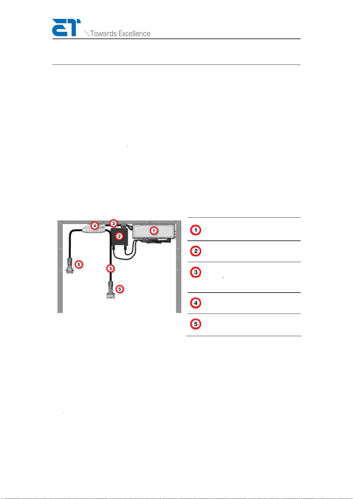
Micr
o
Mod
u
Insu
an e
q
(EG
C
Mid-
C
AC
C
nstallation a
c
c
onnectors
u
w
r microinver
t
m
odule into
t
h
is microinv
e
m
odule on th
r
or to a lar
g
e
rter and its
f
t
he module i
s
r of plu
gg
in
g
d
uced risk h
a
o
inverter
u
le's Junction
lated AC Cabl
e
q
uipment gro
u
C
)
C
able Junctio
n
C
able Connect
o
c
cessories s
u
u
nde
r
load!
w
ww.etsolar.
c
t
er that con
v
t
he alternati
n
e
rter with th
e
e market. Y
o
e, centralize
f
ully-insulat
e
s
fed directl
y
g
the attach
e
a
s the adde
d
Box
e
, which cont
a
u
nding condu
c
n
o
r
u
ch as cable
s
c
o
m
v
erts
ng
e
o
u no
d
e
d AC
y
into
e
d AC
a
ins
c
tor
s
and

www.etsolar.com
7
Grounding in the AC Cables
The AC cable attached to the microinverter and all accessory cables are fully insulated and
contain an equipment grounding conductor (EGC). The full ground path from the transition
cable to the module frame follows:
•The transition cable's green conductor is connected to the EGC from the utility dedicated
branch circuit.
•All connectors have green ground contacts that are longer than the circuit contacts. This
extra length ensures the ground is the first to make contact when connecting modules
and the last to break contact when disconnecting modules.
•The AC ground wire inside the microinverter makes a bolted termination to the
microinverter chassis and is environmentally sealed.
•The microinverter chassis is bonded at the factory to the module frame with stainless
steel hardware to provide ground continuity to the AC PV module frame.
The AC cable grounding path has been tested by a NRTL. Before an AC module assembly can
be labeled with the NRTL certification mark and shipped from an authorized and inspected
factory, each assembly must pass a ground continuity check to verify electrical continuity from
the AC cable ground contact to the module frame.
The AC cable provides equipment grounding for the AC module only. It is the installer's
responsibility to ensure that any metallic parts in contact with the module (i.e. mounting
systems) are provided with a means of equipment grounding according to the manufacturer’s
instructions and local code.
Because the DC power is internal to the module, a grounding electrode conductor (GEC) is not
required.
Because the AC modules are connected in a “daisy chain” fashion, disconnecting one module
from within the string removes power and ground from subsequent modules in the string.
Extreme care should be taken to ensure that no other energized sources are adjacent to these
ungrounded modules, or auxiliary grounding methods must be provided.
If a module is removed from within the strin
g
, it is recommended that you brid
g
e
the gap in the string using an AC extension cable. Inserting an extension cable
maintains ground continuity to subsequent modules in the string. See "AC Wirin
g
Accessories" on page 27 for a list of available extension cables. Other auxiliary
grounding methods may be used.

A b
e
is t
o
cert
g
ro
u
Th
T
hi
s
3-p
h
app
r
T
h
e
T
he
3-p
h
syst
is w
inst
a
syst
Wh
e
rem
1.1
4
tha
t
For
•
e
st practice
f
o
secure the
ified to mee
t
u
ndin
g
elect
r
ree-Pha
s
s
AC module
c
h
ase circuit.
T
r
opriate circ
u
e
AC cable i
s
microinvert
e
h
ase AC syst
e
em. Typicall
y
ired to phas
e
a
llation patt
e
em.
Fi
g
ure
1
e
ther the m
o
ains at 238
W
4
amps nomi
n
t
can be con
n
three 2-pole
•
16 amps
x
f
or all solar
m
module sup
p
t
requireme
n
r
ode system
s
e Instal
c
an be instal
T
he microin
v
u
it.
s
a 4-wire ca
e
r is a sin
g
le
e
m. It is im
p
y
durin
g
inst
a
e
s B and C a
e
rn ensure t
h
1
: Example of
o
dule is insta
W
atts AC. W
n
al current.
U
n
ected to an
, sin
g
le thro
w
x
1.25 (safe
t
m
odule insta
l
p
ort rails an
d
n
ts for
g
roun
d
usin
g
a dedi
lation
led in either
v
erter autom
ble: L1, L2,
N
phase devi
c
p
ortant to ba
a
llation, for
e
nd a third
m
h
at the mod
u
wirin
g
sin
g
le
-
lled on a 24
0
hen connec
t
U
se this nom
AC branch
c
w
20A brea
k
t
y mar
g
in)
=
8
l
lers, especi
a
d
hardware
u
d
in
g
system
s
cated, suita
b
a residential
atically sens
e
N
eutral, and
c
e that is wir
e
lance the n
u
e
ach module
m
odule on ph
u
les are not
c
-
phase microi
0
VAC or 20
8
t
in
g
modules
inal current
t
c
ircuit.
k
ers:
=
20 amps m
a
a
lly those in
a
u
sin
g
g
round
s
. Connect t
h
b
ly sized, co
p
240 Vac spli
e
s the volta
g
Ground.
e
d across t
w
u
mber of mo
d
wired to ph
a
ases A and
C
c
ausin
g
imb
a
n
verter into
a
8
VAC circuit
,
to a 208V c
t
o calculate
t
a
x module
A
w
a
reas with f
r
in
g
hardwar
e
h
e entire str
u
p
per conduc
t
t-phase circ
u
g
e and provi
d
w
o of the thr
e
d
ules wired
t
a
ses A and B
C
(see Fi
g
ur
e
a
lance withi
n
a
3-phase syst
,
the modul
e
ircuit, the m
o
t
he maximu
m
A
C branch cir
w
ww.etsolar.
c
r
equent li
g
ht
e
that has b
e
u
cture to a
t
or.
u
it or in a 20
8
d
es current t
o
e
e phases in
t
o the 3-pha
s
B
, another m
o
e
1). This
n
the 3-phas
e
em
e
's power rat
o
dule produ
c
m
number of
cuit cable ra
c
o
m
nin
g
,
e
en
8
Vac
o
the
a
s
e
o
dule
e
in
g
c
es
units
tin
g

www.etsolar.com
9
•16 amps /1.14 nominal current = 14 modules per branch circuit
•1.14 x 14 modules= 15.96 amps ≤16 amps
Module Layout Diagram
A module layout diagram is a paper model describing the configuration of the array and the
placement of each module in the array. Following the installation, this information is
recreated within the monitoring tool enabling the module owner, service providers, and
system administrators to monitor the performance of each module.
The layout diagram uses the serial number of the microinverter to identify where each module
is installed in the array.
Use the module layout template below to create a module layout diagram of your installation
site.
1. Fill in the data requested at the top of the table.
2. Before a module is installed, peel the serial number sticker from the mid-cable junction.
3. Place the sticker in the same location in the table relative to the microinverter's position
in the actual array.
4. Fill in the sheet number information at the bottom of the table.
5. When complete, use the layout diagram to recreate the array in the monitoring tool.

Table 1: Mo
d
10
d
ule Layout
D
D
ia
g
ram
w
w
ww.etsolar.
c
c
o
m

C
o
1
.
2
.
o
nnectin
g
.
Ali
g
n and
Each con
n
plu
gg
ed
t
close the
.
Snap the
en
g
a
g
ed.
g
Latchi
n
insert the f
e
n
ector has a
t
o
g
ether inc
o
latch.
latch in pla
c
n
g Cabl
e
e
male conne
li
g
nment
g
r
o
o
rrectly. Ens
u
c
e to secure
t
11
e
s
ctor into the
o
ves and rid
g
u
re both en
d
t
he connect
o
latch male
c
g
es that ens
u
d
s are fully s
e
o
rs. Ensure
b
w
c
onnector.
u
re the conn
e
e
ated before
Latch
m
Femal
e
A
lign
m
b
oth sides of
w
ww.etsolar.
c
e
ctors cann
o
attemptin
g
m
ale connect
o
e
connector
m
ent grooves
the latch ar
e
c
o
m
o
t be
to
o
r
e
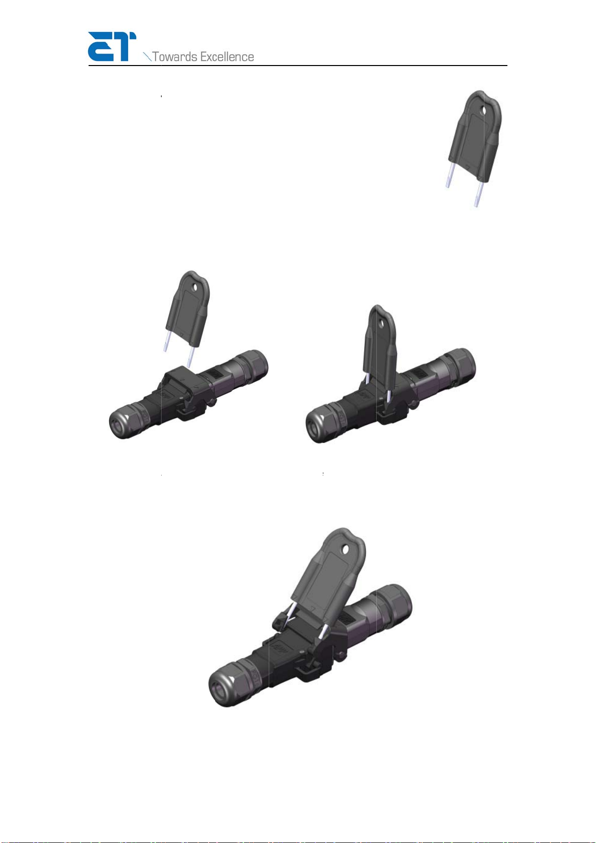
Di
s
Use
1
.
2
.
s
connec
t
the provide
d
.
Insert th
e
feel and
h
.
Use your
t
connecto
r
t
ing Lat
c
d
disconnect
e
ends of the
h
ear a click
w
t
humbs, fir
m
r
until the la
t
c
hing C
a
tool to safe
l
tool into th
e
w
hen the to
o
m
ly push or p
u
t
ch snaps fr
e
12
a
bles
l
y release th
e
e
latch reces
s
o
l is fully sea
t
u
ll the top o
f
e
e.
e
latchin
g
c
o
s
es as shown
t
ed.
f
the disconn
e
w
o
nnectors.
in the ima
ge
e
ct tool tow
a
w
ww.etsolar.
c
e
s below. Yo
u
a
rd the latch
c
o
m
u
will
male

www.etsolar.com
13
Module Preparation
The preparation steps described in this section apply to a large majority of the modules you will
install. Occasionally, however, situations will dictate that the cables be routed differently. Or,
your individual experiences will determine steps or cable management techniques that work
better for you or, more importantly, for your inspectors.
Before you begin preparing the modules for installation, consider the following items, which
might require changes to the cable management of one or more modules:
•Where is the junction or transition box located in relation to the module that will connect
to it?
Whether the box is located to the left or right of the array (as viewed from the ground
facing the installed array) determines which transition cable you need (male or female)
and what preparation is needed for the final module in the string. With the junction or
transition box to the left, a female transition cable is required. The final module in the
string will require an end cap be plugged into the mid-cable junction. With the junction
or transition box to the right of the array, a male transition cable is needed. The final
module will require additional cable management to secure the end of the AC cable.
Before connecting the transition cable, calculate the distance from the transition box to
the module plus the distance under the module to reach the appropriate AC connector.
This will determine the length of transition cable that you will need.
How will you manage the transition cable? If the transition box is under the module, you
might be able to use the module's cable clips to secure the transition cable to the module
frame.
NOTE: Always place cable clips at least three inches from a plug or mid-cable junction to
ensure proper stress relief.
•Do you need any extension cables? Will the extension cable reach from connector to
connector or is it necessary to modify the standard cable management of one or both
modules to make the connection easier?
How will you manage the extension cables? If the extension cables will connect two rows
of modules in the same string, use cable clips to secure the transition cable to the
module frame. Including waves or loops in the cable between clips can help manage
slack.
If the extension cable is running across open roof, another cable management system
will be needed to keep the extension cable off of the roof and protected from the sun. If
the distance to be crossed is longer than the length of the extension cable, you must
transition back to standard building wiring systems to span the distance. Use a transition
T
he
inst
a
mo
d
you
ma
n
Pr
e
AC
m
in t
h
You
'
cable to
c
and NEC
o
preparation
a
llin
g
AC mo
d
ify these in
s
encounter
m
n
a
g
ement pr
a
e
paring
t
m
odules req
u
h
e already at
t
'
re ready to
i
Secu
r
Attac
h
Durin
cauti
o
dam
a
c
onnect the
m
o
r CEC stan
d
and installa
t
dules on mo
s
tructions to
m
ore cable sl
a
ctices to se
c
t
he Mod
u
u
ire minimal
t
ached cabl
e
i
nstall.
r
e the cable i
n
h
the 90degr
e
g shipping, t
h
o
n when unpa
a
ge to the mo
d
m
odule into
a
d
ards.
t
ion instructi
o
st mountin
g
accommoda
t
ack than is
r
c
ure the ex
c
u
les
preparation
e
clip and att
a
n
the S clip.
e
e clip to the
s
h
e AC cable c
o
cking the mo
d
d
ule backshe
e
14
a
j
unction or
o
ns included
systems. In
t
e specific i
n
r
epresented
i
c
ess cable of
f
before insta
a
ch the 90d
e
s
ide frame.
o
nnectors are
d
ule to ensure
e
t or underlyi
n
transition b
o
in this secti
o
some cases
,
n
stallation re
q
i
n these dia
g
f
of the roof.
llation. Sim
p
eg
ree clip to
t
s
ecurely fast
e
the connecto
r
n
g solar cell.
w
o
x and wire
a
o
n are
g
ener
a
,
it mi
g
ht be
q
uirements.
g
rams, use s
t
p
ly secure th
e
t
he side of t
h
e
ned to preve
n
r
s do not swin
w
ww.etsolar.
c
a
ccordin
g
to
a
l instructio
n
necessary t
o
For exampl
e
t
andard cabl
e
connector
c
h
e module fr
a
n
t movement.
g loose and c
a
c
o
m
local
n
s for
o
e
, if
e
c
able
a
me.
Use
a
use

Pr
e
T
he
T
he
into
of t
h
e
paring
t
last module
last module
a nei
g
hbori
n
h
e rooftop.
U
t
he Last
in the strin
g
will have a
n
ng
module.
T
U
se an appr
o
Module
g
will require
n
unused AC
T
his unused
c
o
priate cable
15
in the S
t
a sli
g
htly di
f
connector.
O
c
onnector m
u
clip and en
d
t
ring
f
ferent prep
a
O
ne end or t
h
u
st be secur
e
d
cap as sho
w
w
a
ration.
h
e other will
e
d under th
e
w
n in the fol
l
w
ww.etsolar.
c
not be plu
gg
e
modules a
n
l
owin
g
exa
m
c
o
m
g
ed
n
d off
m
ple:

www.etsolar.com
16
Module Installation
This section describes how to lay down and interconnect AC modules on a previously installed
mounting system. No attempt is made to describe how to install the mounting system on the
roof or how to use module clamps.
Before installing the mounting system, ensure that mounting rails will be positioned below the
microinverter once the module is installed. The microinverter extends beyond the edge of the
frame of most modules. Do not install modules with the microinverter resting on the mounting
rail.
The frame of the installed module must rest firmly on the mounting rail.
Installing a module with the microinverter resting on the rail and uneven
contact between the frame and the rail can cause damage to the
microinverter and the module.
The metal components of the AC module, including frame and
microinverter, can reach temperatures of approximately 80℃. To reduce
risk of burns, use appropriate safety procedures when handling.
Installing the Modules
The ideal installation path is to begin closest to the installed transition box and plug in each
module as you move away from the box. Depending on the configuration of your array and the
location of the transition box, this path may not be feasible. For example, in a 2-row
configuration, we recommend installing the bottom row first and working up toward the
transition box, which is likely mounted higher up the roof.
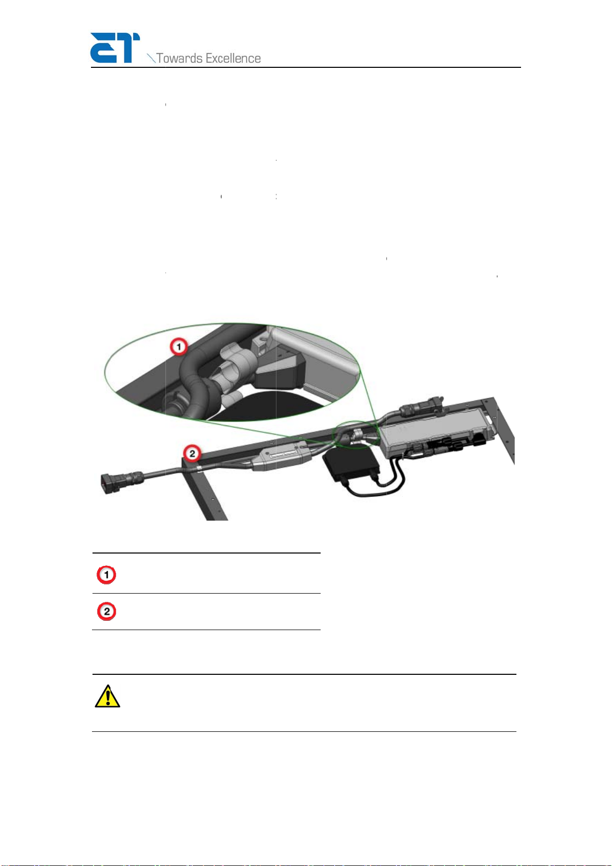
The following diagram shows two installed modules as viewed from the bottom or underside of
the module.

1
.
2
.
3
.
.
Connect
t
local stan
.
Install th
e
instructio
.
Plu
g
the
t
latch.
t
he transitio
n
dards.
e
first modul
e
ns.
t
ransition ca
b
Before co
n
g
round wi
device is i
n
n
cable to th
e
e
, nearest t
o
b
le into the
c
n
nectin
g
mo
d
res are prop
e
n
the OFF p
o
17
e
j
unction o
r
o
the transiti
o
c
onnector of
d
ules to tran
e
rly landed
a
o
sition.
r
transition b
o
o
n box, acc
o
the first mo
sition cable,
a
nd the AC s
w
o
x accordin
g
o
rdin
g
to rac
k
dule and clo
ensure the
n
trin
g
overcu
r
w
ww.etsolar.
c
g
to NEC/CE
C
k
in
g
system
se the conn
e
n
eutral and
r
rent protec
t
c
o
m
C
and
e
ctor
t
ion

www.etsolar.com
18
4. Install the second module.
5. Reach under the top edge of the first module and plug in the AC cable from new module.
Close the latch.
NOTE: For end- or edge-mount racking systems, it might be necessary to lift the top of
the module slightly above the frame to reach the plug.
6. Repeat steps 4 and 5 until you reach the end of the row.
See "Module Preparation" on page 13 for information on preparing the final module in
the string.
If the string will continue to another row, then an extension cable is needed. Plug the
extension cable into the current module and place it in the general vicinity of where the
next module will be installed. Use appropriate cable management strategies to secure
the extension cable.
NOTE: For rail mount systems, lay the extension cable over the rails on which the next
module will be installed. This ensures that the cable remains under the module for
protection from the sun and uses the rails to keep the cable off the roof surface. Once
the module is installed, you can also secure the cable to the module frame with cable
clips, if necessary.
Table of contents
Popular Control Unit manuals by other brands


Emerson
Emerson Raimondi HPA 150 Installation & maintenance instructions

IBM
IBM color LaserJet 5500 Operational, installation, and maintenance guide

Siemens
Siemens SENTRON 7KM PAC 4DI/2DO operating instructions

ARAG
ARAG BRAVO 300S Quick reference guide

Siemens
Siemens SIMATIC ET 200SP HA System manual

Pfeiffer Vacuum
Pfeiffer Vacuum EVI 105 PI instruction sheet


