Et system EAC/AFV User manual

ET System electronic GmbH
Telefon 06205 3948-0
Fax 06205 37560
Hauptstraße 119-121
68804 Altlußheim
www.et-system.de
EAC/AFV

Software version:
January 2015

Table of Contents
Info & Contact Addresses............................................................................................................................................1
Technical Specifications ..............................................................................................................................................1
Ambient Conditions........................................................................................................................................................1
Display............................................................................................................................................................................2
Input Specifications ........................................................................................................................................................2
Output Specifications .....................................................................................................................................................2
Total Power ....................................................................................................................................................................2
Technical Drawing ..........................................................................................................................................................3
Important Safety Instructions .....................................................................................................................................4
Initial Operation .............................................................................................................................................................4
Unpacking.......................................................................................................................................................................4
Setting Up.......................................................................................................................................................................4
Visual Inspection ............................................................................................................................................................4
Mains Operation ............................................................................................................................................................4
Functional Description ................................................................................................................................................5
Block Diagram.................................................................................................................................................................5
Structure of the Main Control Unit ................................................................................................................................6
Description of cable connections ...................................................................................................................................6
Cable Wiring ...................................................................................................................................................................6
General Settings..........................................................................................................................................................7
Initial State & Splash Screen...........................................................................................................................................7
Main Menu .................................................................................................................................................................7
Application.................................................................................................................................................................7
System .......................................................................................................................................................................7
Event..........................................................................................................................................................................7
Menu “APP“ ...................................................................................................................................................................8
Mode “General“ ........................................................................................................................................................8
Mode “Step“..............................................................................................................................................................9
Mode “Gradual“ ......................................................................................................................................................10
Mode “Meas.“ .........................................................................................................................................................11
Error Message..........................................................................................................................................................12
Menu “SYSTEM“ ...........................................................................................................................................................12
Date & Time.............................................................................................................................................................13
System Setting .........................................................................................................................................................13
Language Setting .....................................................................................................................................................13
Menu ”EVENT“ .............................................................................................................................................................13
RS 485 Interface ........................................................................................................................................................14
Command Format ........................................................................................................................................................14
Commands of Functions...............................................................................................................................................14
Answer Commands ......................................................................................................................................................14
Protocol Examples........................................................................................................................................................15
CRC Check Sum.............................................................................................................................................................18
Error Messages..........................................................................................................................................................19
Maintenance.............................................................................................................................................................19
Notes ........................................................................................................................................................................20


Info & Contact Addresses
ET System electronic GmbH 1
INFO & CONTACT ADDRESSES
ET System electronic GmbH was founded in 1986 in the heart of the Rhine-Neckar-Triangle. As a subsidiary of a leading
electricity utility group, the company quickly took on a leading role in the area of laboratory power electronics and
associated electrical measurement. The existing know-how in power technologies in the 90s gave rise to the “Power
Solutions” product division as a strong extension of the historical “Test & Measurement” range.
Since 1997, we have been working successfully as an independent, privately held company with customers in all lines
of business from industry, medical care, railway technology and automotive electronics.
By means of our high vertical range of manufacture and our ever expanding development division we can fast and
flexibly adjust to our customers’ requirements. Necessary approvals such as CSA, UL, VDE, TÜV etc. are flexibly carried
out by qualified personnel. The approval procedures are performed within the scope of development planning and thus
do not negatively impact the start of manufacturing. Permanent manufacturing control through accredited laboratories
and an ISO 9001 compliant quality management system guarantee a constant high-level series-production quality.
We offer repairs and adjustment for units outside of our warranty period. Please contact your local distributor for fur-
ther information:
Place of Business: Altlußheim, Germany
VAT Identification Number: DE 144 285 482
Register Court: Mannheim, Germany
Register Number: HRB 421186
Managing Director: Dipl.-Ing. Eric Keim
Sales Manager: Roland Kosmowski
Development Leader: Hermann Amtsberg
TECHNICAL SPECIFICATIONS
AMBIENT CONDITIONS
Operating Temperature
0 - 45 °C
Operating Height
< 1.500 m
Insulation Resistance
≥ 500 V DC 10 MΩ
Insulation Test Voltage
AC 1.800 V 10 mA/1 min
Cooling
Fan
Humidity
< 90 %
Germany
ET System electronic GmbH
Hauptstraße 119-121
68804 Altlußheim
Germany
Phone: +49 (0) 6205 39480
Fax: +49 (0) 6205 37560
em@il: info@et-system.de
web: www.et-system.de

Technical Specifications
2 ET System electronic GmbH
DISPLAY
Display
Touch screen
Voltage
Display: 0 - 300 V, Resolution: 0.1 V, Accuracy: 0.5 % FS + 4COUNT
Current
Display: 0 - 999,9 A, Resolution: 0.1 A, Accuracy: 0.5 % FS + 4COUNT
Frequency
Display: 0 - 999,9 Hz, Resolution: 0.1 Hz, Accuracy: ± 0.1 Hz
INPUT SPECIFICATIONS
Number of Phases
3
Voltage
230/400 V
Voltage Fluctuation
230/400 V ± 15 %
Frequency Fluctuation
50/60 Hz ± 3 Hz
Power Factor
0.9
Max. permitted current under full load
140.3 A
OUTPUT SPECIFICATIONS
Number of Phases
3
Wave Form
Sine
Low Voltage
0 - 150 V (L - N)
High Voltage
150.1 - 300 V (L - N)
Frequency
45 - 500 Hz
Frequency Stability
±≤ 0.01 %
Max. high voltage current
LO: 83.3 A
Max. low voltage current
HI: 41.7 A
TOTAL POWER
Output Power (kVA)
75
Circuit Mode
IGBT/PWM (pulse width modulation)
Voltage Control
≤ 1 %
Load Control
± 1 %
Wave Form Distortion (THD)
≤ 2 %
Efficiency
≥ 90 %
Reaction Time
≤ 2 ms
Crest Factor
3:1
Protective Devices
Input: fuse switch, Output: overvoltage/undervoltage, overcurrent, overload Input:
overvoltage/undervoltage, countercurrent protection, overtemperature, short circuit protec-
tion, conduct fast protection and lock fault protection , error display
Technical Specifications
ET System electronic GmbH 3
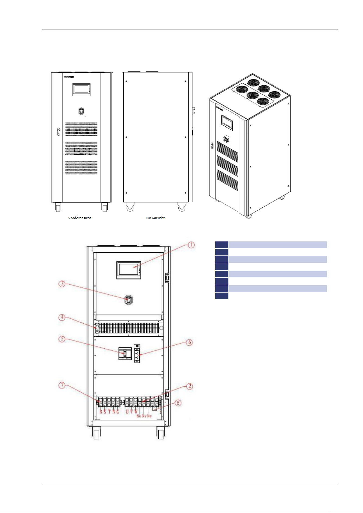
TECHNICAL DRAWING
1
Touchscreen
2
AC Output terminal row: U, V, W, Nu, Nv, Nw
3
Emergency stop button
4
Door handle
5
Input air switch
6
Maintenance socket
7
AC input terminal row: R, S, T, N, G
8
Parallel operation
Important Safety Instructions
4 ET System electronic GmbH
IMPORTANT SAFETY INSTRUCTIONS
Please read this manual thoroughly before putting the device
into operation. Pay regard to the following safety instructions
and keep this manual nearby for future purpose.
This operating manual is based on the state of technology at the time of printing. However, it is possible that despite
regular control and correction, the present document contains printing errors or deficiencies. ET System electronic
GmbH assumes no liability for any technical, printing or translational errors within this manual.
INITIAL OPERATION
UNPACKING
Please make sure that the shipping carton and the packaging is free of damage. If external damage is found, it is im-
portant to record the type of damage. Please keep the original packaging to ensure the device is adequately protected
in case it needs to be transported in the future or claims for compensation need to be asserted.
SETTING UP
To avoid electric shocks and product failure, the device should be installed in a temperature and humidity controlled
indoor environment. The ambient temperature must not exceed 50 °C. The device must never be exposed to liquids or
extreme humidity.
VISUAL INSPECTION
The unit must be examined immediately for defects or damages in transit. Damages caused during transport may be
loose or broken control knobs and bent or broken connectors. Do not use the device if any physical damage is apparent.
Please inform the carriers and a representative of ET System electronic immediately.
MAINS OPERATION
Make sure to verify the model number and voltage stated on the nameplate. Damages due to wrong power feed are
not covered by guarantee conditions.
The unit must only be operated when connected directly to the
mains. To avoid damage, do not connect the unit to
isolating transformers, auto -transformers, magnetic current
limiters or similar devices.

Functional Description
ET System electronic GmbH 5
FUNCTIONAL DESCRIPTION
BLOCK DIAGRAM
The following block diagram gives information about the various adjustment options.
Description:
1 Input
connection between power supply endpoint and input terminal disk
2 Input Air Switch
power input control
3 Input Filter
input inductor and capacitor filter
4 Rectifier Filter
converts input alternating current into direct current
5 Soft Start
D.C. capacitor is charged slowly to reduce impulse current
6 Inverter Circuit
converts direct current into PWM waveform
7 Transformer Filter
boosts the output voltage of IGBT and outputs the voltage after LC filter
8 Output
output voltage is transferred to the output terminal disk through the contactor
9 Lightning Protection Device
overvoltage protection, lightning protection, restraining surge current, absorbing spike pulse, etc.
10 Voltage Sampling
input voltage sampling conditioning circuit
11 SCR Drive
drives the control circuit of soft start SCR
12 IGBT Drive
amplifies PWM signals to drive IGBT power components
13 Voltage Feedback
steady output voltage amplitude
14 Voltage/Current Sampling Circuit
samples conditioning circuit of output voltage and current
15 Power Supply
power supply of all PCB
16 Main Control Circuit
processes all input and output signals
17 Display
touch screen display
18 EPO
emergency stop signal
19 Fuse Detection
transmits the fuse power-off signal to the control circuit for trip protection
20 Over-temperature Detection
transmits the over-temperature signal to the control circuit for trip protection

Functional Description
6 ET System electronic GmbH
STRUCTURE OF THE MAIN CONTROL UNIT
The main control unit is divided into three modules: protection sampling, main control, display control.
DESCRIPTION OF CABLE CONNECTIONS
The following picture gives an overview about the cable connections of the main circuit:
Before installing the equipment, all switches need to be disconnected. The circuit cables must be connected according
to the diagram above.
CABLE WIRING
Use the voltmeter to confirm whether there is no voltage output in the distribution lines. Confirm whether all switches
of the variable frequency power supply are in the position “OFF”. The input and output cables can be selected according
to the cables recommended in the following tables.
Input distribution cables:
Input Current (A)
Input live wire (mm²)
Input zero line (mm²)
Input ground wire (mm²)
A
B
C
70.8 A
25 mm²
25 mm²
25 mm²
16 mm²
16 mm²
Output distribution cables:
Output Current (A)
Output live wire (mm²)
Output zero line (mm²)
Output ground wire (mm²)
U
V
W
LO: 83.3 A - HI: 41.7 A
25 mm²
25 mm²
25 mm²
25 mm²
16 mm²
The above recommended reference cables are multi-core flexible copper cables which can be selected by the user ac-
cording to the present input and output current situation. If the length of the input or output lines exceeds 20 meters,
it is recommended that the wire diameter of the cable should be doubled. Successively connect the input distribution
lines to the corresponding wiring terminals at the input and the output distribution lines to the corresponding wiring
terminals at the output.
General Settings
ET System electronic GmbH 7
GENERAL SETTINGS
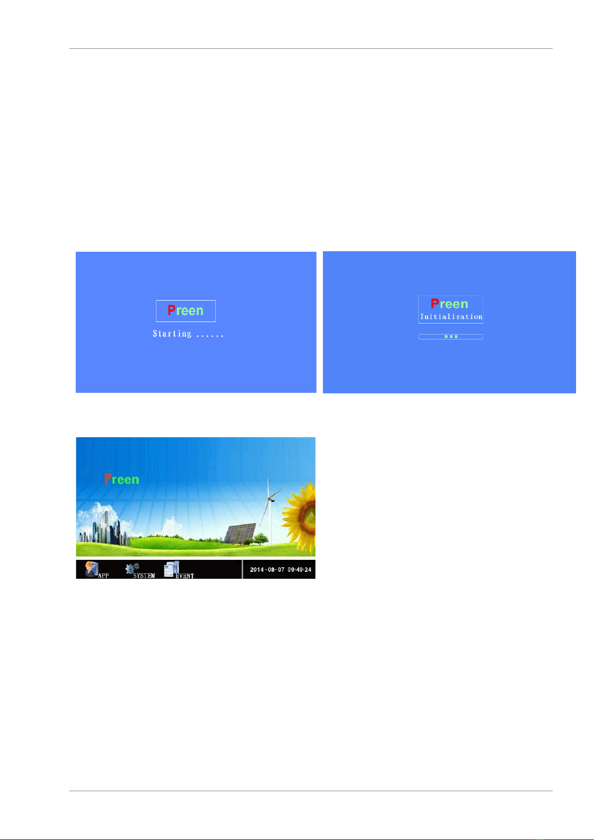
INITIAL STATE &SPLASH SCREEN
The input and output wirings should be connected properly. If the system is started, the main engine fan will start to
operate, the display screen is on and the main interface is entered, indicating that the start-up is normal and the pa-
rameter settings can be entered.
If an external load is connected, the load switch must be disconnected and the input switch connected. Before, the user
should ensure, that no electrical current is flowing at the input terminal row.
When switching on the unit, the splash screen and the initialization graphic will appear on the display.
MAIN MENU
Application
The menu APP displays voltage, current and frequency for each phase of the output terminal. For detailed information,
see chapter →Menu APP.
System
The menu System enables the user to adjust time and other system settings. For detailed information, see chapter →
Menu SYSTEM.
Event
The menu Event records event protocols and information. For detailed information, see chapter →Menu EVENT.
Main Menu
8 ET System electronic GmbH
MENU “APP“
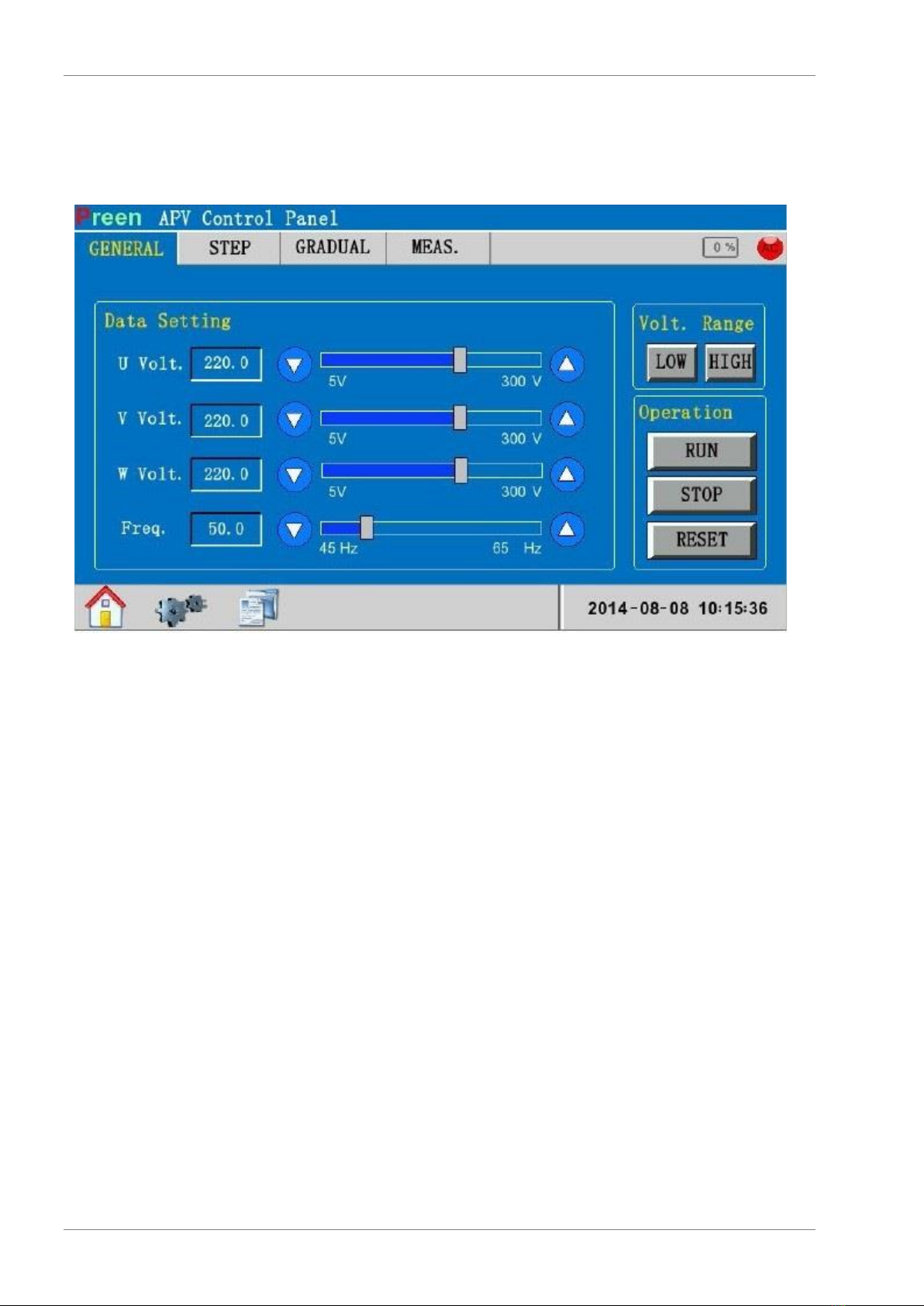
Mode “General“
Data Setting
The adjustment of the values for U Volt., V Volt., W Volt. and Freq. (Frequency) can be adjusted in three ways. A click
on the input field opens the dialog box where the desired value can be entered via keyboard. Alternatively, the value
may be adjusted via slide control and mouse. A third option for entering the values are the arrow buttons besides the
slide control. By clicking these buttons, the value changes by 0.1 interval.
Volt. Range
After clicking the button LOW, the unit is on low voltage. After clicking the button HIGH, the unit is on high voltage.
Operation
The output of the unit is activated when the button RUN is clicked. Deactivate the output by clicking the button STOP.
AC Symbol
The AC symbol in the upper right corner of the display shows the status of the unit output. A red symbol means the
output is inactive, while a green symbol means the output is active.

Main Menu
ET System electronic GmbH 9
Mode “Step“
Download Parameter
Starts the download of the adjusted parameters.
Operation
Mode ”Step“ is activated after button RUN was clicked, and deactivated after button STOP was clicked. RESET sets
the unit back to its initial state.

Main Menu
10 ET System electronic GmbH
The button in the upper right field of the display switches between adjustment function and graphical display of the
mode “Step”.
Mode “Gradual“
Download Parameter
Starts the download of the adjusted parameters.
Main Menu
ET System electronic GmbH 11
Operation
Mode ”Gradual“ is activated after button RUN was clicked, and deactivated after button STOP was clicked. RESET
sets the unit back to its initial state.
The button in the upper right field of the display switches between adjustment function and graphical display of the
mode “Gradual”.
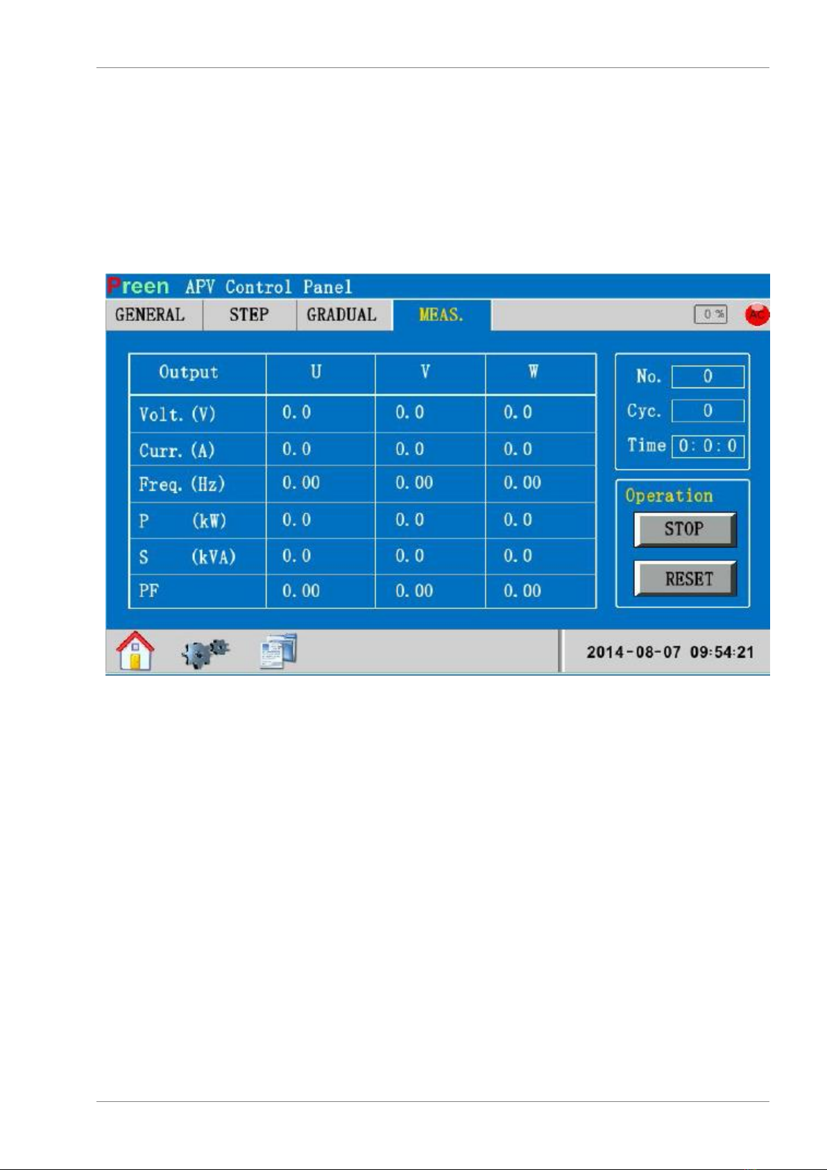
Mode “Meas.“
Operation
The mode “Meas.“ (realtime sampling) is paused after the button STOP was clicked. A click on the button RESET sets
the unit back to its initial state.
Main Menu
12 ET System electronic GmbH
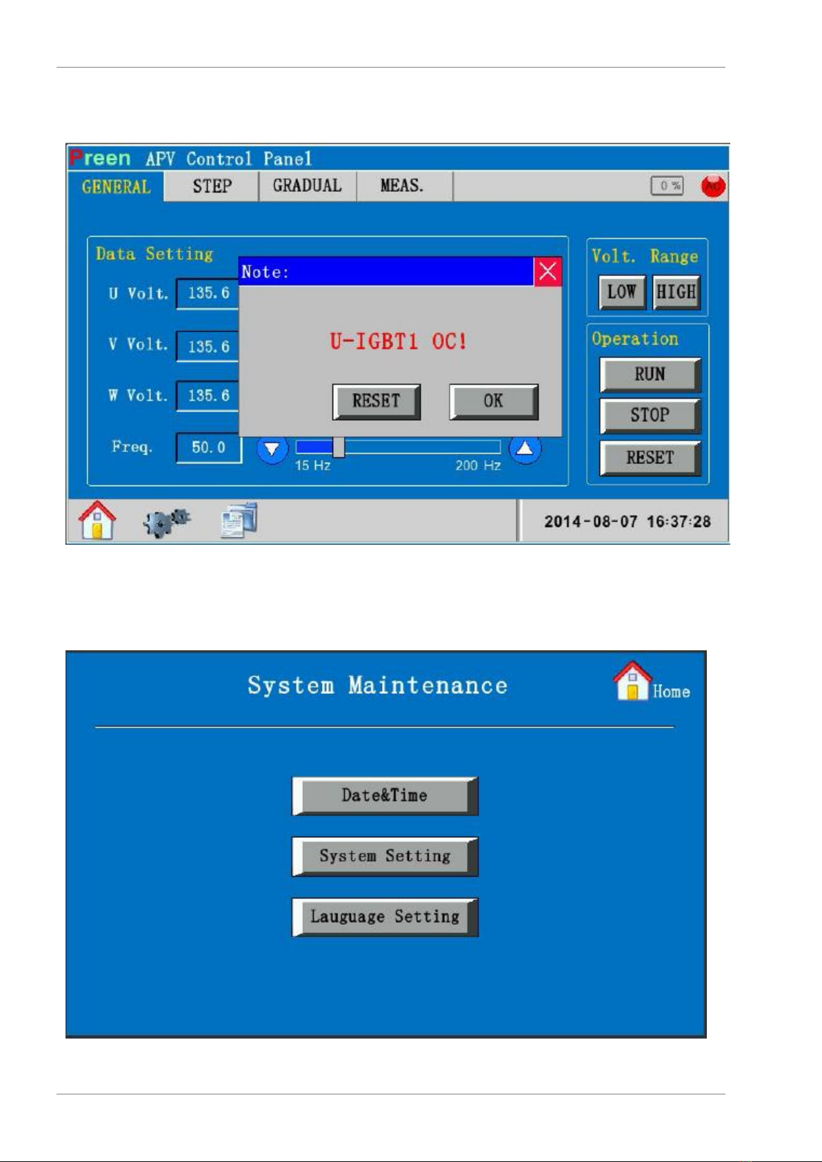
Error Message
Operation
A click on the button RESET resets the error meassage. Clicking OK switches to the previous display.
MENU “SYSTEM“

Main Menu
ET System electronic GmbH 13
Date & Time
Date and time can be entered via keyboard. The button Back saves these settings and switches to the previous menu.
System Setting
System settings may be read but cannot be changed by the user. In case, that adjustments shall be made, please contact
our service.
Language Setting
Adjusts the menu language. The button Back saves these settings and switches to the previous menu.
MENU ”EVENT“
Operation
Clicking on the button Previous/Next browses the unit log. The button Clear deletes all saved protocols. The button
Back saves settings and opens the previous menu.

RS 485 Interface
14 ET System electronic GmbH
RS 485 INTERFACE
COMMAND FORMAT
Ad-
dress
Function
Length
Data Range
CRC Check
Addr
Func
Len
{data}
CRC_H CRC_L
COMMANDS OF FUNCTIONS
Control
0x00~0x0F
Adjustment
0x10~0x1F
Adjustment Data Functions
0x20~0x2F
Data Enquiry
0x30/0x31
Application parameter
0x16~0x17
Command for standard address
0x02
ANSWER COMMANDS
0 x 02
Address
0 x 50
Function
0 x 01
Command length
0 x 00
Status:
00 –Communication on
01 - Timeout Error
02 - Parity Error
0 x 00
CRC Checksumme high byte
0 x 1D
CRC Checksumme low byte

RS 485 Interface
ET System electronic GmbH 15
PROTOCOL EXAMPLES
Command
Function
Command example
Control examples
Operation
0x01
Send command:
0x02 address
0x01 function code
0x02 command length
0x00 0x01 Operation type:
0x01—general mode function operation
0x02—step mode function operation
0x03—gradual mode function operation
0x04—Three-phase voltage independent setting function
0x05/0x06—reserved
0x07—Voltage disturbances run
0x08—Frequency disturbances run
0x09—Voltage and Frequency disturbances run
0x3C CRC Checksum high byte
0x3C CRC Checksum low byte
Answer from unit:
0x02 0x50 0x01 0x00 0x00 0x1D
Stop
0x02
Send command:
0x02 address
0x02 function code
0x00 command length
0xD1 CRC Checksum high byte
Answer from unit:
0x02 0x50 0x01 0x00 0x00 0x1D
Reset
0x03
Send command:
0x02 address
0x03 function code
0x00 command length
0xD0 CRC Checksum high byte
0xF0 CRC Checksum low byte
Answer from unit:
0x02 0x50 0x01 0x00 0x00 0x1D
Remote Control
0x04
Send command:
0x02 address
0x04 function code
0x04 command length
0x00 0x01 Remote control connection: 0-disconnect, 1-connect
0x00 0x01 reserved
0x58 CRC Checksum high byte
0x84 CRC Checksum low byte
Answer from unit:
0x02 address
0x04 function code
0x0A command length
0x00 0x01 operation status: 0-stop, 1-run
0x08 0x98 current output voltage
0x01 0xF4 current output frequency
Output voltage
0x07
Send command:
0x02 address
0x07 function code
0x02 command length
0x00 0x00 Output voltage in high or low segment
0x00—Output voltage in low segment
0x01—Output voltage in high segment
0x3C CRC Checksum high byte
0xB4 CRC Checksum low byte
Answer from unit:
0x02 0x50 0x01 0x00 0x00 0x1D

RS 485 Interface
16 ET System electronic GmbH
Command
Function
Command example
Application Settings
General information (AC)
0x20
Send command:
0x02 address
0x20 function code
0x04 command length
0x08 0x98 current output voltage (220 V x 10)
0x01 0xF4 current output frequency (50 Hz x 10)
0x40 CRC Checksum high byte
0xb9 CRC Checksum low byte
Answer from unit:
0x02 0x50 0x01 0x00 0x00 0x1D
Note: The command RUN has to be send again if voltage or current were
adjusted before.
Adjustment mode “STEP“
0x21
Send command:
0x02 address
0x21 function code
0x0A command length
0x00 0x01 Group number(1-24)
0x08 0x98 output voltage of this group(220V×10)
0x01 0xF4 output frequency of this group(50Hz×10)
0x00 0x00 0x00 0x0A execution time of this group(10second)
0x7C CRC Checksum high byte
0xF1 CRC Checksum low byte
Answer from unit:
0x02 0x50 0x01 0x00 0x00 0x1D
Adjustment mode “GRADUAL“
0x22
Send command:
0x02 address
0x22 function code
0x0E command length
0x00 0x01 Group number (1-12)
0x04 0x4C output voltage of this group (110 V x 10)
0x01 0xF4 output frequency of this group (50 Hz x 10)
0x08 0x98 output voltage of this group (220 V x 10)
0x02 0x58 output frequency of this group (60 Hz x 10)
0x00 0x00 0x00 0x0A execution time of this group (10 Sekunden)
Answer from unit:
0x02 0x50 0x01 0x00 0x00 0x1D
Voltage adjustment 3phase (AC)
0x23
Send command:
0x02 address
0x23 function code
0x08 command length
0x08 0x98 current R-phase output voltage (220 V x 10)
0x08 0x98 current S-phase output voltage (220 V x 10)
0x04 0x4C current T-phase output voltage (110 V x 10)
0x01 0xF4 current output frequency (50 Hz x 10)
0x63 CRC Checksum high byte
0xF2 CRC Checks
Answer from unit:
0x02 0x50 0x01 0x00 0x00 0x1D
Adjustment of application parameters
Mode “STEP“ Loop adjustment
0x16
Send command:
0x02 address
0x16 function code
0x06 command length
0x00 0x01 starting group number of step-mode loop
0x00 0x18 ending group number of step-mode loop
0x00 0xFF loop number
0x09 CRC Checksum high byte
0x31 CRC Checksum low byte
Answer from unit:
0x02 0x50 0x01 0x00 0x00 0x1D
Mode “GRADUAL“ Loop adjustment
0x17
Send command:
0x02 address
0x17 function code
0x06 command length
0x00 0x01 starting group number of Gradual-mode loop
This manual suits for next models
1
Table of contents
Other Et system Power Supply manuals


