Et system EAC-4Q-GS User manual
Manual
Vertrieb Kontakt: Tl.: +49 (0)6205 / 394 80
Sales contact:
info@ t-syst m.d
Bidirektionale
AC-Quellen EAC-4Q-GS
Bidirectional
AC Sources EAC-4Q-GS
Hauptstraße 119 – 121
D – 68804 Altlußheim
ET Syst m l ctronic GmbH
www.et-system.de

Original
INFO & CONTACT ADDRESSES
ET System electronic GmbH was founded in 1986 in the heart of the Rhine-Neckar-Triangle. As a subsidiary of a
leading electricity utility group, the company quickly took on a leading role in the area of laboratory power electronics
and associated electrical measurement. The existing know-how in power technologies in the 90s gave rise to the
“Power Solutions”product division as a strong extension of the historical “Test & Measurement”range.
Since 1997, we have been working successfully as an independent, privately held company with customers in all lines
of business from industry, medical care, railway technology and automotive electronics.
By means of our high vertical range of manufacture and our ever-expanding development division, we can fast and
flexibly adjust to our customers’requirements. Necessary approvals such as CSA, UL, VDE, TÜV etc. are flexibly carried
out by qualified personnel. The approval procedures are performed within the scope of development planning and
thus do not negatively impact the start of manufacturing. Permanent manufacturing control through accredited
laboratories and an ISO 9001 compliant quality management system guarantee a constant high-level series-
production quality.
We offer repairs and adjustments for units outside of our warranty period. Please contact your local distributor for
further information:
Place of Business:
VAT Identification Number:
Register Court:
Register Number:
Altlußheim, Germany
DE 144 285 482
Mannheim, Germany
HRB 421186
Germany
ET System electronic GmbH
Hauptstraße 119-121
68804 Altlußheim
Germany
Phone: +49 (0) 6205 39480
Fax: +49 (0) 6205 37560
em@il: info@et-system.de
web: www.et-system.de

Legal Notices
Without the written permission and consent of ET System, no part of this manual may
be used, copied, translated, modified, or transmitted in any form. All the information,
instructions and illustrations provided in this manual are the latest version currently. This
manual is based on the technical status at the time of printing. ET System will make
every effort to ensure that the information in this manual is up-to-date and accurate. It
will be modified without notice. Although there are regular controls and corrections, there
may still be typographical errors or defects. ET System has no liability for any technical,
typographical or translation errors in this manual. If any errors are found, please report
them in writing.
The pictures used in this manual do not represent the pictures of the products actually
purchased by the user. The actual products purchased by the user may be customized
versions, which may not match the manual in terms of appearance, weight and
technical parameters. For specific understanding of the actual appearance and technical
parameters of related products, please contact ET System.
Software Statement
EAC-4Q-GS series provides GUI software, which is installed on the TFT-Touch panel using
the Windows OS. Unless interoperability requires by law, it is prohibited to reverse
program, disassemble or decompile the software.

Safety Requirements
Summary of safety requirements
Please read the manual thoroughly before putting the equipment into operation. Pay regard
to the following safety instructions and keep the manual nearby for future purpose to avoid
any damage to the equipment. To prevent potential hazards, please follow the instructions
in the manual to safely use the instrument. ET System electronic GmbH have no liability for
failures caused by violate protective measures or other safety regulations.
•Unpacking
Please make sure that the shipping carton and the packing is without any damage.
If any external damage is found, it is important to record the type of damage. Please
keep the original packing to ensure the product is adequately protected in case it
needs to be transported to the factory or make a claim.
•Surroundings
To avoid electrical hazards or product failure, the equipment should be installed indoor
which meets the environment requirements.
•Operator
The equipment operator must follow the warnings, safety instructions and
accident prevention measures in the manual.
•Visual Inspection
After unpacking, please immediately check whether there is any defects or damage
of the equipment during transportation. If there is obvious physical damage, please do
not use the equipment. Please notify the carrier and the agent of ET System electronic
GmbH immediately.
•Power Operation
Please confirm the model and voltage / current rating on the nameplate before
operating. Damage caused by wrong power supply is not covered by the warranty.
•Use Suitable Cables
Please select the appropriate cable according to the equipment specifications of the
local country.
•Equipment Groundin
The equipment is grounded through the protective ground bus. To avoid electrical
hazards, connect the ground terminal to the protective ground terminal before
connecting any input or output terminals.
•Appropriate Overvoltage Protection
Make sure that there is no overvoltage on the product (such as overvoltage
caused by lightning). Otherwise, the operator may be in danger of electrical hazards.
•Avoid Exposing Circuits or Wires
When the module is powered on, do not touch the exposed connectors or
components.

Safety Notices and Symbols
Safety Symbols
SHOCK HAZARD WARNING PROTECTIVE EARTH
TERMAINAL
Other Symbols
IMPORTANT INFORMATION
Safety Information
WARNING
If improperly operated, it may cause injury or danger immediately.
WARNING
Potentially dangerous situation or practice. If not avoided, it
will result in serious
injury or death.
CAUTIOUS
Potentially dangerous situation or practice. If not avoided, may result in product
damage or loss of important data.
SHOCK HAZARD
Danger, caution or warning caused by electricity. To avoid the risk of electric
shock, the power supply must be firmly connected to the ground wire and other
equipment wiring. Within a few seconds after the power supply is
off, the high
voltage at the output terminal may be maintained. Do not
touch the cable or
terminal block immediately.
IMPORTANT INFORMATION
Important information when operating the equipment/software.

Content
Safety Requirements ................................................................................................................. 4
Part I Equipment Introduction................................................................................................. 10
1.1 System Overview ..................................................................................................... 11
1.1.1 Overview of EAC-4Q-GS series .................................................................................... 11
1.1.2 Model Description ........................................................................................... 11
1.1.3 Features and configuration ............................................................................. 11
1.1.4 General Specification ...................................................................................... 12
1.2 Appearance and structure of Equipment ................................................................ 14
1.2.1 Appearance and outline .................................................................................. 14
1.2.2 Front Panel ...................................................................................................... 14
1.2.3 Rear panel ....................................................................................................... 16
1.2.4 Internal structure ............................................................................................ 17
1.2.5 Front panel of control module ........................................................................ 17
1.2.6 Connection layer and other interface layers ................................................... 18
1.3 Interface Description ............................................................................................... 20
1.3.1 LAN interface(standard) ............................................................................. 20
1.3.2 RS485 nterface (standard) ............................................................................... 21
1.3.3 RS232 interface (-232 option) ......................................................................... 22
1.3.4 TTL interface (standard) .................................................................................. 24
1.3.5 ATI Interface (-ATI option) ............................................................................... 25
1.3.6 External emergency stop interface (standard) ................................................ 26
1.3.7 Remote sense interface (standard) ................................................................. 27
1.3.8 Master-slave interface(-MS option) ........................................................... 29
Part II Equipment Installation .................................................................................................. 32
2.1 Check before Installation ......................................................................................... 33
2.1.1 Check the packing ........................................................................................... 33
2.1.2 Check the equipment ...................................................................................... 33
2.2 Equipment Installation ............................................................................................ 34
2.2.1 Selection of input/output cables ..................................................................... 34
2.2.2 Installation steps ............................................................................................. 34
2.2.3 Add single-phase output (-1P option) ............................................................. 36
2.3 Parallel installation of equipment ........................................................................... 37
Part III Power-on Operation .................................................................................................. 40
3.1 Power-on Operation ................................................................................................ 41
3.2 GUI Software Operation (Local Control).................................................................. 43
3.3 GUI Software Operation(Remote Control) ........................................................... 45
3.4 Power off Operation ................................................................................................ 46

Part IV Function and Feature Introduction............................................................................... 48
4.1 Grid Simulation Function......................................................................................... 49
4.2 Re-generative AC Load (-LD option) ........................................................................ 52
4.3 Extends to DC output (-DC option) .......................................................................... 53
4.4 Line impedance (RL) Simulation (-IMP option) ....................................................... 53
Part V Software Interface ................................................................................................... 54
5.1 GUI Software Introduction ...................................................................................... 56
5.1.1 Operating status .............................................................................................. 56
5.1.2 Sequence mode ............................................................................................... 57
5.1.3 Input/output controls ...................................................................................... 58
5.2 Communication Setting ........................................................................................... 60
5.3 Hardware Limits ...................................................................................................... 62
5.4 Sequence ................................................................................................................. 64
5.5 Analog Input ............................................................................................................ 66
5.6 AC/AC+DC/DC .......................................................................................................... 67
5.6.1 AC .................................................................................................................... 67
5.6.2 AC+DC .............................................................................................................. 68
5.6.3 DC (-DC option) ............................................................................................... 69
5.7 Harmonic and inter-harmonic simulation ............................................................... 70
5.7.1 Harmonic simulation ....................................................................................... 70
5.7.2 Inter-harmonic simulation ............................................................................... 71
5.8 Simulation of Re-generative AC Load ...................................................................... 73
5.8.1 CR mode .......................................................................................................... 73
5.8.2 Rectifier mode ................................................................................................. 74
5.8.3 CC/CP phase lead/lag mode ............................................................................ 75
5.9 Measurements ........................................................................................................ 76
5.10 Waveform ................................................................................................................ 77
5.10.1 Real-time waveform browsing ........................................................................ 77
5.10.2 Historical waveform browsing ......................................................................... 78
5.11 System Status .......................................................................................................... 80
5.12 Administrator Account ............................................................................................ 81
Part VI Equipment verification and calibration ................................................................... 82
6.1 Performance Verification ........................................................................................ 83
6.1 1 Verity equipment and settings ............................................................................... 83
6.1.2 Verity content .................................................................................................. 85
6.2 Test Record Form ............................................................................................................... 91
Part VII Equipment Maintenance and Repair..................................................................... 92
7.1 Equipment Maintenance ................................................................................................... 93
7.1.1 Equipment operating environment ................................................................. 93
7.1.2 Equipment maintenance ................................................................................. 93

7.2 Equipment Repair .................................................................................................... 94
7.2.1 Equipment self-test ................................................................................................ 94
7.2.2 Maintenance service .............................................................................................. 94
7.2.3 Equipment returns .......................................................................................... 94
Part VIII Programming ........................................................................................................... 95
8.1 Command Format ................................................................................................... 96
8.1.1 Parameters data type ...................................................................................... 96
8.1.2 Command parameters/Return valve units ...................................................... 96
8.1.3 Command format ............................................................................................ 96
8.2 Command Sets ........................................................................................................ 97
8.2.1 Common commands ....................................................................................... 97
8.2.2 SCPI and panel comparison ........................................................................... 101
8.3 Example ................................................................................................................. 110

Part I Equipment Introduction
1.1 System Overview
1.1.1 Overview of EAC-4Q-GS
1.1.2 Model description
1.1.3 Features and configuration
1.1.4 General specification
1.2 Appearance and Structure of Equipment
1.2.1 Appearance and outline
1.2.2 Front panel
1.2.3 Rear panel
1.2.4 Internal structure
1.2.5 Control module of front panel
1.2.6 Connection layer and other interface layers
1.3 Interface Description
1.3.1 LAN interface (standard)
1.3.2 RS485 interface (standard)
1.3.3 RS232 interface (232 option)
1.3.4 TTL interface (standard)
1.3.5 ATI Interface (-ATI option)
1.3.6 External emergency stop interface (standard)
1.3.7 Remote sense (standard)
1.3.8 Master-Slave interface (-MS option)

1.1 System Overview
1.1.1 Overview of EAC-4Q-GS series
The EAC-4Q-GS is a high-performance and multi-functional grid simulator, using advanced PWM
technology, which contains multiple output power levels from 30kVA to 500kVA and above for
single system, and up to 4 individual systems can be paralleled to achieve power levels up to
2MVA. The maximum output power of the customized system goes up to 4MVA and above. It
uses bi-directional design, which can be used as grid simulator in varieties of applications such as
in Smart Grid, Energy Storage, Solar etc.
With touch panel on the front panel, user can control
the power source through GUI software. System status indicators and emergency stop
button are installed on the front panel.
The programming interface includes standard RS485
and LAN interfaces, as well as optional RS232 and analog control interfaces, which can be used for
automated test applications.
1.1.2 Model Description
1.1.3 Features and configuration
▪
Single system from 30kVA to 500kVA and parallel up to 4MVA and above
▪
4 quadrant operation, regenerative up to 100% of rated output powerback to grid (-R option)
▪
Independent three-phase output
▪
Up to 50th harmonic waveform generation
▪
Voltage drop simulation (LVRT for inverter test)
▪
Regenerative AC load function (-LD option)
▪
Line impedance (RL) simulation (-IMP option)
▪
Voltage and frequency sequencing programming via GUI software, slew rate can be
programmed
▪
ON and OFF output phase angle can be programmed
▪
Current limit can be programmed, output can be shorted for short circuit test
▪
Trigger out, TTL signal output for voltage or frequency change
▪
Extend output frequency to DC (-DC option)
▪
Add single phase output (-1P option)
▪
Use water-cooling (-W option)
▪
Master-Slave interface (-MS option)
▪
TFT-Touch panel operation
▪
LAN/RS485 interfaces (standard), RS232/Analog control interfaces (optional)
▪
Mod-bus/SCPI protocols
▪
Emergency stop button
▪
Switchable insulation monitoring
▪
Output contactor
▪
Remote sense
▪
CE conformity
▪
Customized voltage, current and power ranges
1.1.4 General Specification
Output Input
Output Modes AC AC input Voltage 3P+N+PE, 380VLL±10%(std)
Power Level
30kVA~500kVA in single
controller, 2MVA max power
available, Customizable
Frequency 47-63Hz
Voltage Ranges 0-300V L-N (std), customizable Efficiency ≥90%
Current Ranges Customizable Power Factor 0.95
Frequency range Standard 30-100Hz
Phase output
Phase B/C relative to phase A,
0.0~360.0° Measurements
Harmonic
Generation Up to 50th Power Accuracy 0.5%FS
Load Regulation 0.2%FS Voltage Accuracy 0.5%FS
Line Regulation 0.1%FS Current Accuracy 0.3%FS
THD <1% (Resistive Load) Frequency
Accuracy 0.01Hz
Power Accuracy 0.5%FS Phase accuracy <1.2° (@50Hz)
Voltage Accuracy 0.5%FS
Current Accuracy 0.3%FS Others
Frequency
Accuracy 0.01Hz Protection OVP, OCP, OTP
Phase accuracy <1.2° (@50Hz) Regulatory CE Conformity
Power Resolution 0.1kW Cooling Forced Air Cooling
Voltage Resolution
0.1V Temperature
Operating: 0~40°C
Storage: -20~85°C
Current Resolution
0.1A Operating
Humidity
20-
90%RH (None
Condensing)
Frequency
Resolution 0.01Hz

Power Level 30kVA 60kVA 120kVA 250kVA 500kVA
Voltage Range
0-300V L-N
Output
current 46A/ph 91A/ph 182A/ph 379A/ph 758A/ph
Dimension 800*800*1900 800*800*2200
2*800*800*2200 2*900*900*2200
4*900*900*2200
(W*D*H mm)
Weight <800kg <1000kg <1700kg <2500kg <5000kg
*other Power/Voltage Level can be offered. Contact Sales.

1.2 Appearance and structure of Equipment
1.2.1 Appearance and outline
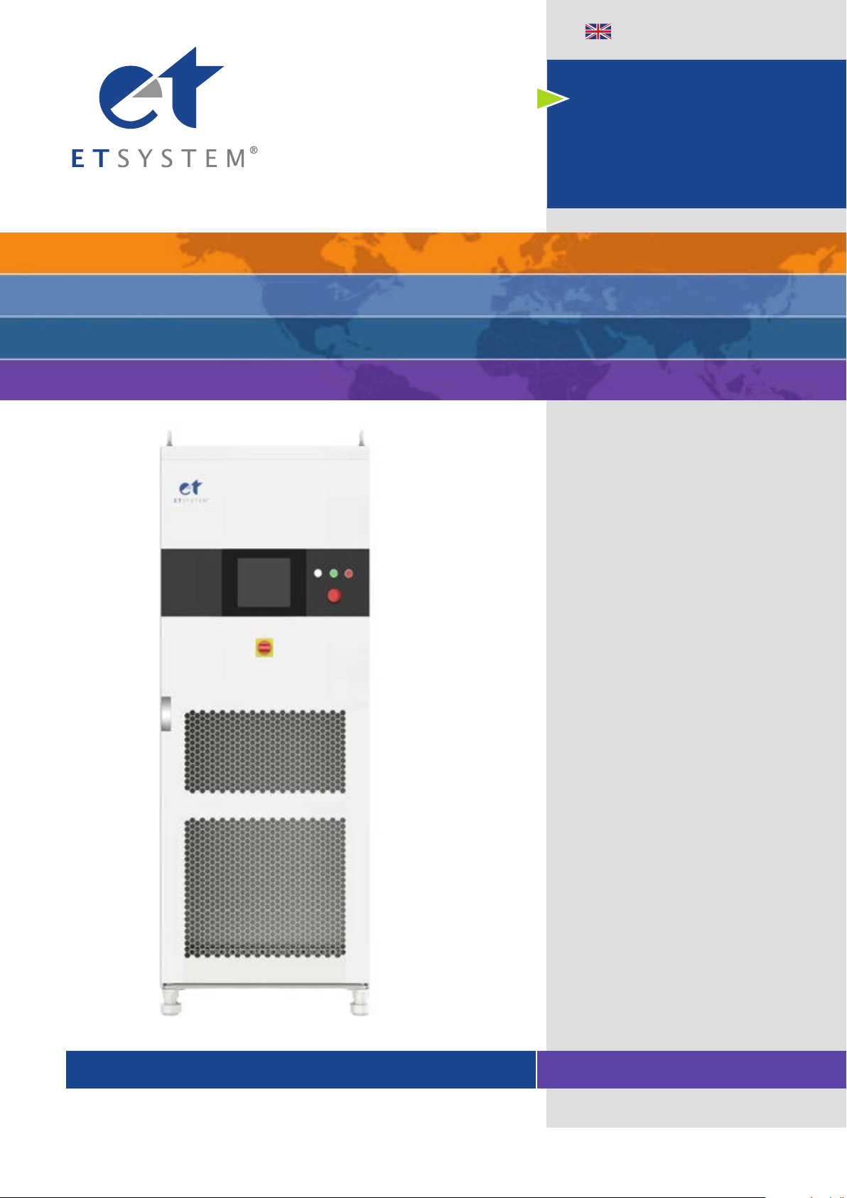
The overall appearance of the EAC-4Q-GS (take EAC-4Q-GS 30-300-46 as an example) is
shown in Figure 1-1. There are lifting rings at the top of the cabinet for lifting operation and
moving rollers at the bottom of the cabinet for users to move flexibly. There are TFT-Touch
panel displayer (12 inch), status indicator, power knob, emergency stop button and RS232
interface (optional) on the front panel, product brand, RS485/ LAN interface (standard),
TTL interface (standard), ATI interface (optional) which is for automated test applications
on the rear panel.
Figure 1-1 Overall appearance
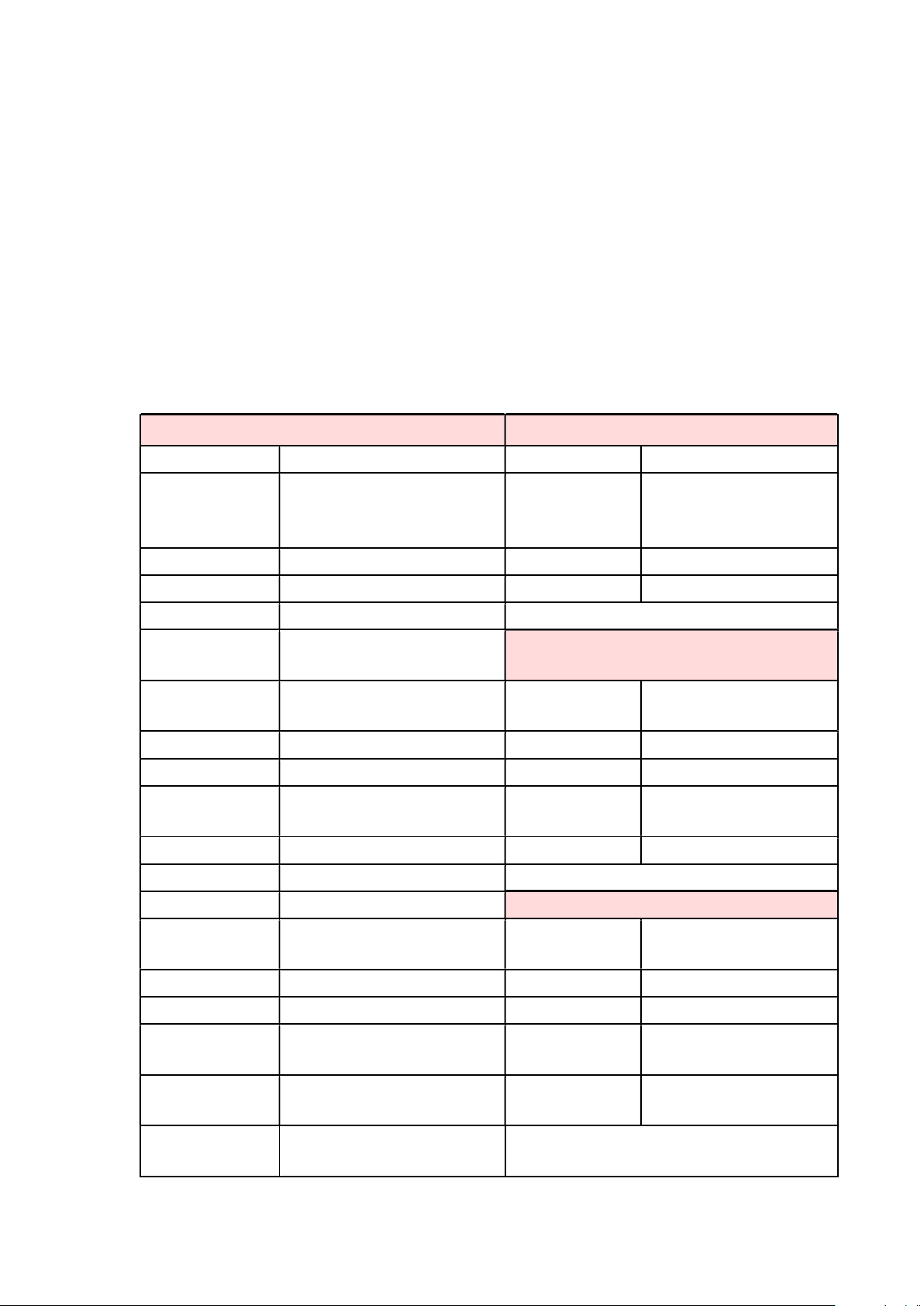
1.2.2 Front Panel
The front panel of EAC-4Q-GS series is equipped with a TFT-Touch panel displayer (12
inch), status indicators, power knob, emergency stop button and RS232 interface (optional).
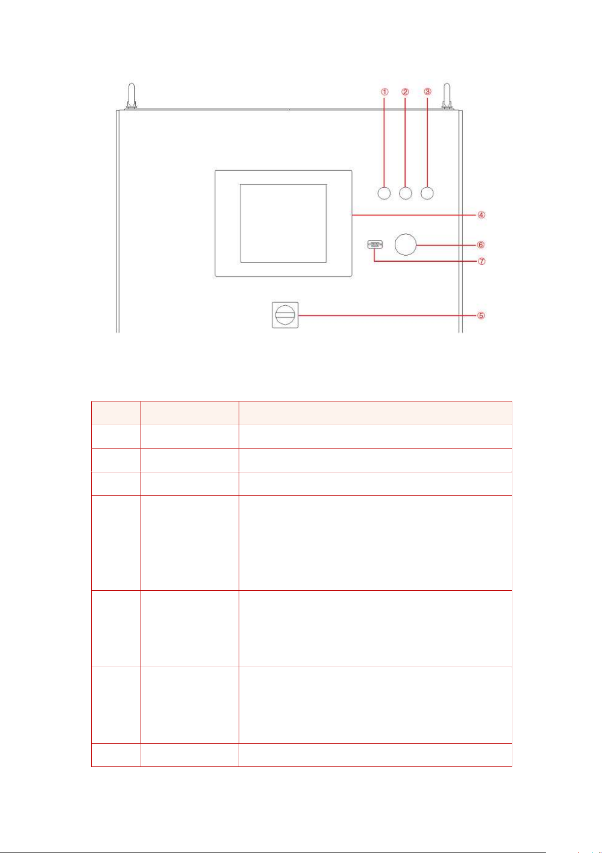
Figure 1-2 Front panel
Table 1-1
Number
Name Notes
① White Light The power supply is standby.
② Green Light The power supply is operating normally.
③ Red Light The power is failure.
④ TFT-Touch Panel
Capacitive TFT touch panel displayer (12 inch), using the
Windows OS., provides a GUI software
, and has the
functions of setting system parameters, output
parameters, measurements, capturing and saving
Waveform, and displaying failures.
⑤ Power Knob
The User can use power knob to turn on / off the power
without opening the cabinet door. Turn the control module
clockwise to power on
and turn the control module
counterclockwise to power off.
⑥ Emergency Stop
Button
The emergency stop button is only used in the event of an
emergency. Do not press the button under normal working
conditions. Turn the emergency stop butt
on clockwise to
the right can cancel the emergency braking.
⑦ RS232 interface Optional, for remote control (-232 option)
1.2.3 Rear panel
The rear panel of EAC-4Q-GS is equipped with RS485/LAN interface (standard),
TTL interface(standard) and ATI interface (optional).
Figure 1-3 Rear panel
Table 1-2
Number
Name Note
①RS485 interface Standard configuration, used for remote control.
② LAN interface
Standard configuration, it is a communication interface,
and used for remote control.
③ TTL
Standard configuration, for users to observe the trigger
signal after connecting with the oscilloscope.
④ ATI interface
a. Analog control interface-Phase A
b. Analog control interface-Phase B
c. Analog control interface-Phase C
Optional, analog control interface (-ATI option)
⑤ Product brand The input / output configuration of the product is marked.

1.2.4 Internal structure
As shown in Figure 1-4, take EAC-4Q-GS 200-300-300 as an example, from top to bottom,
the internal modules of EAC-4Q-GS series are: ①control box layer, ②module layer, ③other
input/output component layer, ④wiring layer and other interface layers.
Figure 1-4 Internal structure
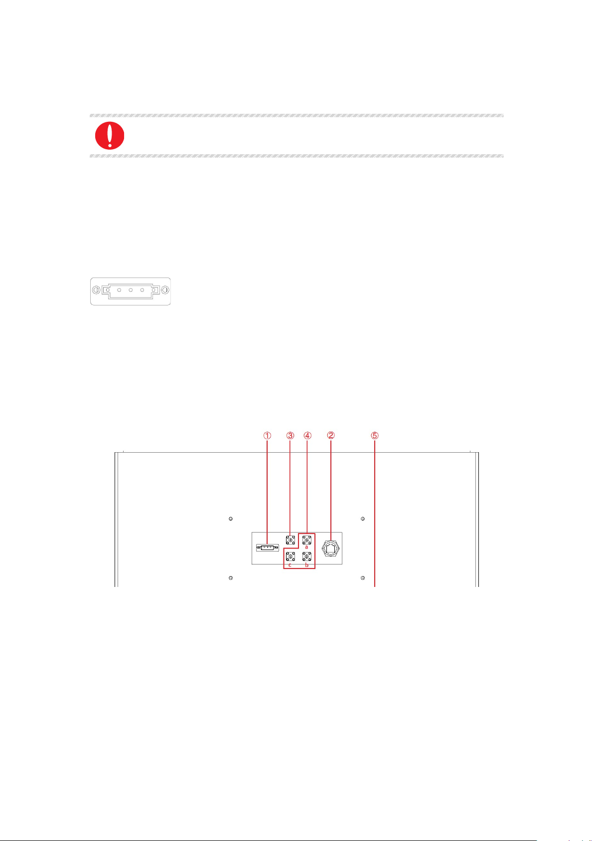
1.2.5 Front panel of control module
The front panel of EAC-4Q-GS series control module is equipped with LAN interface
(standard), Master-Slave interface (option), fan, and power switch.

Figure 1-5 Front panel of control module
Table 1-3
Number
Number Notes
① LAN interface Standard, for touch screen communication
② LAN interface Standard, for debugging and firmware update
③ Fan For control module heat dissipation
④ Power switch For the power on / off the control module
⑤ Master-Slave
interface
Optional, for communication between power supply.
when power supply
of the same power is connected in
parallel
(Refer to 1.3.8.2 for specific wiring method) (-MS option)
1.2.6 Connection layer and other interface layers
The power input/output wiring copper bar, 220V auxiliary terminal, external emergency stop
interface and remote sense interface are showed when remove the bottom baffle, as shown
in Figure 1-6.

Figure 1-6 connection layer and other interface layers
Table 1-4
Number
Name Notes
①Wiring copper bar of input side From left to right are PE, N, A, B, C
②Wiring copper bar of output side From left to right are N, A, B, C
③Other terminals
a + b → Control module 220V auxiliary power
terminals (+, -) (No need to wire)
c + d → External emergency stop interface (+, -)
e+f →A phase remote sense interface(+,-)
g+h →B phase remote sense interface(+,-)
i+j →C phase remote sense interface(+,-)
IMPORTANT INFORMATION
Figure 1-6 takes EAC-4Q-GS 200-300-300 as an example. Affected by the
output voltage/current level, electrical clearance and creepage distance, the
position of the output copper bar and other terminals may change. Please
refer to the final design of the project.

1.3 Interface Description
1.3.1 LAN interface(standard)
The LAN interface is one of the equipment communication interfaces.
1.3.1.1 Location of LAN interface
The two LAN interfaces on front panel of the control module are used for touch panel
communication (Figure 1-7①) and hardware debugging (Figure 1-7②).
Figure 1-7 front panel of the control module
IMPORTANT INFORMATION
The LAN interface (Figure 1-7①) is connected to the touch panel by defaul
t before
shipment. Do not remove it without permission.
The interface (Figure 1-7②) is used for debugging before shipment. Do not use it
without permission.
The LAN interface located on the rear panel is used for remote control of equipment (Figure
1-8②).
Figure 1-8 Rear panel
1.3.1.2 Connection of LAN interface
Please refer 5.2 for detail connection method.
IMPORTANT INFORMATION
The network wire used for LAN connection is Straight-Through Wired Cable.
1.3.1.3 Remote control setting
Please refer 5.2. for detailed remote control setting method.
1.3.2 RS485 nterface (standard)
The RS485 interface is one of the equipment communication interfaces. It
is used for remote control and can effectively transmit signals under long-distance conditions
and in environments with high electronic noise. RS485 interface makes it is possible to connect
to local network and configure multi-drop communication link.
1.3.2.1 Location of RS485 interface
The RS485 interface is located on the rear panel of power supply (Figure 1-9①).
Figure 1-9 Rear panel
1.3.2.2 Connection of RS485 interface
The RS485 interface of EAC-4Q-GS series adopts "two-wire + signal ground" wiring. In low-
speed, short-distance, non-interference occasions, ordinary twisted-pair wire can be used.
Conversely, in high-speed and long-line transmission, RS485 special cable (STP-120Ω 18
AWG) (one pair) with impedance matching (generally 120Ω) must be used. In the
environment with severe
Table of contents
Other Et system Power Supply manuals


