BEHLMAN P1350 Use and care manual

-I-
USER'S GUIDE AND
TECHNICAL REFERENCE
BEHLMAN MODEL P1350 “POWER PASSPORT”
1.35 KVA AC POWER SUPPLY
_________________
FOR SERVICE ASSISTANCE
CONTACT BEHLMAN
CUSTOMER SERVICE DEPARTMENT
PHONE TOLL FREE 1-800-874-6727
OR WRITE
BEHLMAN ELECTRONICS CORPORATION
CUSTOMER SERVICE DEPARTMENT
80 CABOT COURT
HAUPPAUGE, NY 11788-3729
PHONE: (631) 435-0410
FAX : (631) 951-4341
FOR SALES INFORMATION:
PHONE: (631) 435-0410(NY) OR (805) 375-7046 (CA)
USA : 1-800-874-6727(NY) OR (800) 456-2006(CA)
FAX : (631) 951-4341(NY) OR (805) 498-2147(CA)
DATE: 3/16/10 REV. A

-II-
SAFETY SUMMARY
The following safety precautions must be observed during all phases of operation,
service, and operation of this equipment. Failure to comply with these precautions
or with specific warnings elsewhere in the manual violates safety standards
associated with the design and intended use of this equipment.
GROUND THE EQUIPMENT
To minimize shock hazard, the equipment chassis(s) must be connected to an electrical
safety ground. This equipment is supplied with a three conductor line connection for single
phaseapplicationsorafivewireconnectionforthreephaseapplications.Bothtypesinclude
an earth terminal intended for safety ground connections. In addition,installation sites may
require neutral to earth connections as per NEC section 250 ( National Electrical Code ).
Refer installation to licenced electrician or other qualified personnel.
DO NOT OPERATE IN EXPLOSIVE ATMOSPHERE
Do not operate the equipment in the presence of flammable gases or fumes. Operation of
any electrical instrument in such an environment constitutes a definite safety hazard.
KEEP AWAY FROM LIVE CIRCUITS
Operating personnel must not remove equipment covers. Component replacement and
internal adjustments must be made by qualified maintenance personnel. Do not replace
components with power applied. Under certain conditions, dangerous voltage may exist
even with the power removed. To avoid injuries, always disconnect power and discharge
circuits before touching them.
DO NOT SERVICE OR ADJUST ALONE
Do not attempt internal service or adjustment unless another person, capable of rendering
first aid and resuscitation is present .
DO NOT SUBSTITUTE PARTS OR MODIFY INSTRUMENT.
Because of the danger of introducing additional hazards, do not install substitute parts or
perform any unauthorized modification to this equipment. Contact Behlman Electronics for
proper replacement parts and specific service information.
DANGEROUS PROCEDURE WARNINGS
Warnings will precede potentially dangerous procedures in this manual. Instructions
contained in the warning must be followed.

-III-
CLAIM FOR DAMAGE IN SHIPMENT
Under the FOB factory terms of sale, ownership and responsibility are transferred to the customer when the
equipment leaves the factory. Each Behlman equipment is shipped from the factory in proper operating
condition.
Immediately upon receiving equipment, unpack and inspect it for evidence of damage incurred in shipment.
Fileaclaimwith thefreight carrierifthe equipmenthasbeen damagedin anyway orit failsto operateproperly.
Forward a copy of the damage claim report to Behlman. Include the model number, serial number and date
theshipmentwasreceived.Behlmanwilladvisethedispositionoftheequipmentandwillarrangefornecessary
repair or replacement.
RETURNING EQUIPMENT TO FACTORY
Do not return equipment to the factory without prior authorization from Behlman.
A RETURN MATERIAL AUTHORIZATION NUMBER (RMA) is required to return equipment.
This equipment, like all precision electronic equipment, is susceptible to shipping damage. It contains heavy
magnetic components as well as delicate electronic components.
If equipment is returned without prior authorization, the shipment will be refused, the customer being liable for
all shipping, handling and repair costs.
When packing for reshipment, use the original shock absorbent material and shipping container to preclude
damage to the equipment.
Insure that the return authorization numbers (RMA) is available on the container for identification.
SHIPPING INSTRUCTIONS
RACK MOUNTED UNITS
1) Box (es) must be double wall with minimum 350 lbs. bursting test.
2) Box(es) mustprovide fora minimumof 3to4 inchesofclearance aroundsides,top andbottom ofunit.
3) Whenpacking unit,utilize eithera foam-in-place systemor high densityfoam. Clearance provided for
above must be completely filled with foam.
FAILURE TO COMPLETELY SECURE UNIT IN BOX WILL ALLOW
MOVEMENT DURING SHIPPING, RESULTING IN DAMAGE.
4) Securebox(es)topallet(s). Thisisnecessarytoinsureproperhandlingandprotectionduringshipping.
5) Place the following warning label on box (es)
DO NOT STACK
6) Ship unit (s) using a freight cargo carrier; air or ground.
CABINET MOUNTED UNITS
Cabinetmountedunitsrequirethataspecialcratebeused. Thecrateshouldbemanufacturedofplywood(3/8"
or thicker) and reinforced (using 1 x 3 or larger pine) on all edges. The unit must be firmly secured to the
crate’s base. The crate must be shock mounted to avoid damage during shipping. Detail drawings for
Behlman's crates are available upon request.

-IV-
WARRANTY CERTIFICATE
Behlman Electronics, Inc. warrants to the original purchaser, for a period of one (1) year from the shipment
from Behlman, each item to be free from defects in material and workmanship. Behlman’s obligation and the
Purchaser’s sole remedy for any breach or violation of this agreement is limited to adjustments, repair or
replacements for parts which have been promptly reported by the Purchaser as having been in its opinion,
defective and so found by Behlman upon inspection. All replacement parts will become the property of
Behlman on an exchange basis. This warranty will not apply if such adjustment repair or parts replacement
is required because accident, neglect, misuse, failure of environmental controls, transportation damage or
causes other than normal use.
If during the warranty period adefect should impair the performanceofthe unit, Behlman agrees, atits option,
to repair or replace the unit or its defective components F.O.B. Behlman at 80 Cabot Court, Hauppauge NY
11788 or at another Behlman service facility at Behlman’s option. To obtain service under this warranty, the
original Purchase shall notify Behlman at the above address or by telephone at 631-435-0410 and provide
informationabout the defectorimpairmentof performance. Behlman withthen supply the Purchaser a Return
MaterialAuthorization(RMA)number.Thisnumbermustbeattachedtotheequipmentsentbackforwarranty
repair. Equipment must be shipped back to Behlman prepaid. No collect shipments will be accepted.
Behlman shall be excused from supplying warranty service if the unit’s case has been open or if the unit has
been subject to unauthorized repair. All service outside the scope of this warranty shall be paid for by the
Purchaser at Behlman’s rates in effect at the time of this repair. Behlman will not perform any repairs outside
of the warranty without written authorization by the Purchaser. If the repair is a warranty repair, Behlman will
ship the unit back to the Purchaser, by a method determined solely by Behlman, prepaid. If the Purchaser
requests, any other means of transportation it shall be at the Purchaser’s expense.
The use of the equipment shall be under the Purchaser’s exclusive management and control. The Purchaser
will be responsible for assuring the proper installation, use, management and supervision of the equipment.
Behlman will not be liable for personal injury or property damage.
The forgoing warranties are in lieu of all other warranties, expressed or implied including without limitation
warranties of merchantability and fitness for purpose.
In no event shall Behlman be liable for loss of profits, loss of use, or any indirect, consequential or incidental
damages. Purchaser agrees that Behlman will not be liable for any damages caused by the Purchaser’s failure
to fulfill any of the Purchaser’s responsibilities set forth herein.

-V-
THIS PAGE INTENTIONALLY BLANK
INSERT ADDENDUMS HERE

1
TABLE OF CONTENTS
BEHLMAN AC POWER SOURCE, MODEL P1350
SECTION
1.0 INTRODUCTION
1.1 SPECIFICATIONS
2.0 UNPACKING AND INSTALLATION
2.1 Unpacking
2.2 Installation
2.3 Power Requirements
3.0 OPERATING INSTRUCTIONS
3.1 Typical Operation
3.2 Connecting Loads
3.3 Output Adaptors
3.4 Operating Under Fault Conditions
3.5 Troubleshooting
4.0 OPERATING CONSIDERATIONS
4.1 Operating Into Linear Loads
4.2 Driving Reactive Loads
4.3 Driving Lamps
4.4 Driving Motors
4.5 Driving Non- Linear Loads
4.6 Input Power Requirements
4.7 Output Noise
4.8 Mechanical Outline
4.9 Rack Mount Option
5.0 AVAILABLE OPTIONS
5.1 Analog Remote Control option -4065

2
SECTION 1
P1350 AC POWER SUPPLY INTRODUCTION
The Behlman model P1350 AC Power Source is a solid state frequency converter. It provides regulated AC
power at frequencies that are not available from local utility power. The output of the model P1350 is
transformercoupledprovidinganisolatedvoltagesourcesimilartoutilitypower.ThemodelP1350incorporates
the latest in hard switched,PWM technology. A high frequency“ClassD” type outputstage provides asavings
in weight and waste heat. This accounts for the compact size and high power capability of this AC power
source. The following is a brief description of the conversion process performed by the P1350.
Line power at 120 VAC 47 - 440Hz is applied to the input of the unit. After passing through a noise filter, the
input AC is converted to a bulk DC voltage. This DC voltage is applied to the output inverter ( refer to the block
diagram below ). The output inverter is a switch mode power amplifier. A sine wave signal of the desired
frequency is developed by the control circuitry and applied to the input of the power amplifier. This sine wave
is amplified and “stepped - up” by the output transformer to provide the proper voltage. The output voltage of
the unit is sensed electronically and used as feedback to regulate the output. This action rejects fluctuations
in the input line voltage and provides an output that may be adjusted above or below the input line. The output
current of the power source is monitored and used to provide overload protection for the output inverter.

3
SECTION1
P1350 AC POWER SUPPLY INTRODUCTION
P1350 AC POWER SUPPLY SPECIFICATIONS
INPUT REQUIREMENTS: 120 VAC +/- 10% 47-440 Hz
OUTPUT POWER: 1350 VAC MAX. ( with input @ 120 VAC)
LOAD POWER FACTOR: Zero to Unity with no derating.
OUTPUT VOLTAGE: 0 -135VAC @ 10 AMPS AND 0-270VAC @ 5 AMPS
OUTPUT FREQUENCY: Fixed at 50, 60 , & 400Hz. Switch selectable +/- .01 Hertz
OUTPUT REGULATION: Less than 1% of full scale from no load to full load
SETTLING TIME: Approximately 200mSec to 1%. 10-90% (linear load)
LINE REGULATION: +/- 0.1% for +/- 10% line change @ 115V 10A/230 5A
OUTPUT DISTORTION: 1% Typical @ 115 V 50Hz into pure resistive load
.
OUTPUT NOISE : 2.5 V peak to peak typ.( on low range into 10 ohms )
FRONT PANEL METER:
VOLTMETER RESOLUTION: 1 Volt
ACCURACY: 2% of reading + ( +/- 1digit ) RMS responding
PROTECTIVE CIRCUITS:
SHORT CIRCUIT Inverter latches off in response to output short. Response time less than
20usec.
CONSTANT CURRENT Responds to long term overloads by reducing output voltage. Set @
approximately110%ofratedcurrent forrangeinuse. 250mSecapproximate
response time.
MISCELLANEOUS:
PHYSICAL Steel chassis, 17" W x 17.5" D x 3.5" H. 45 lbs.
TEMPERATURE RANGE 0 - 55 Degrees Celsius (operating) -10C to +65C (storage)

4
SECTION 2
P1350 AC POWER SUPPLY UNPACKING AND INSTALLATION
2.1 UNPACKING
After unpacking the equipment, carefully conduct a thorough inspection of all controls, indicators, and
chassis. If the unit shows signs of shipping damage, do not attempt to operate. File a damage claim
with the responsible carrier. Notify Behlman immediately.
2.2 INSTALLATION
This device is designed to operate on a bench or desk top. It can be mounted in a standard 19 inch
rack cabinet using the RM option. DO NOT ! ATTEMPT TO MOUNT BY RACK “EARS” ONLY.Rear
support must be provided. See information for the RM option contained elsewhere in this manual.
It is preferable to operate this equipment in a location which will maintain an air temperature of 0 to
40 degrees C around the ventilation ports. If the unit is to be rack mounted, the enclosure must be
ventilated. The installation should insure that the side and rear vents are unobstructed.
2.3 INPUT POWER REQUIREMENTS
Thismodelissuppliedwith astandardIEC20 type linecordwithanNEMA 15Pmoldedtothelineend.
This cord is rated at 15A and will suit most applications. The Model P1350 can operate from a wide
input voltage range but continuous full power operation requires a “stiff” 120V line capable of suppling
atleast20A.The cordshouldbereplacedwithan IEC20plugwired withthedesired 20Aplugto match
the user’s receptacle. Consult with qualified electrician or Behlman if in doubt.
!WARNING !
This equipment produces AC leakage current that may exceed dangerous levels. This
equipment is supplied with a three-wire AC input that provides for a safety earth connection
to the equipment chassis. For operator safety the chassisof the equipment must be connected
to the installation site safety earth. The safety earthconnection also provides a return path for
leakage currents associated with the equipment’s internal line filter. Leaving this connection
floating may create a shock hazard and/or electromagnetic interference.
IMPORTANT NOTE:
Theoutputof thepower supplyis floatingand alsoprovidesa safetyearthconnection. Itispermissible
to tie one side of the output to the safety earth. This will allow the power supply to conform to section
250 of the National Electrical Code (NEC). Consultation with a qualified electrician is recommended
for permanent installations in buildings or vehicles.
This equipment is designed to be operated in a dry indoor location. Do not operate in the presenceof
rain or other moisture.
5
SECTION 3
P1350 AC POWER SUPPLY OPERATING INSTRUCTIONS
!WARNING !
THIS DEVICE PRODUCES VOLTAGE AND CURRENT LEVELS WHICH CAN BE LETHAL.
MIS APPLICATION OF THIS DEVICES MAY CAUSE SERIOUS INJURY OR DEATH.
THIS DEVICE IS INTENDED FOR USE BY QUALIFIED PERSONNEL ONLY !
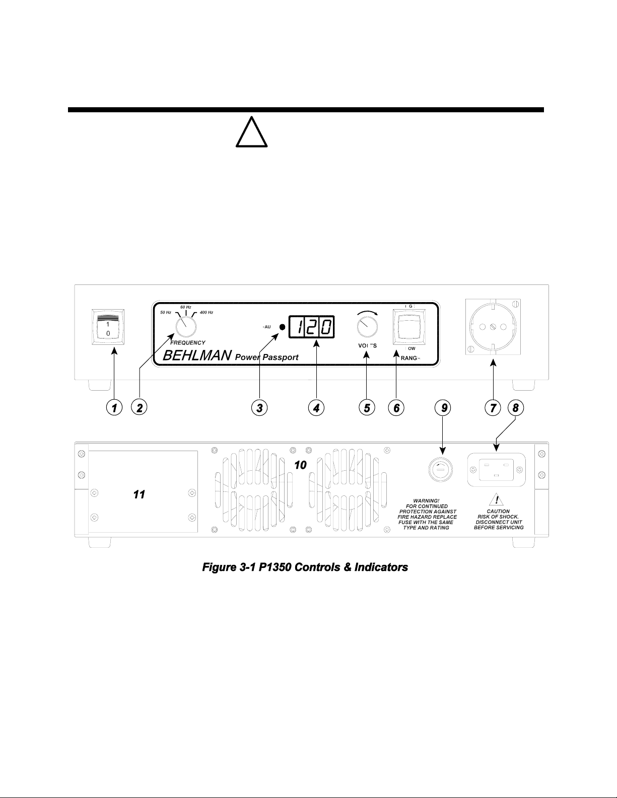
ThefollowingsectionprovidesdescriptionsofthevariousfeaturesoftheMODELP1350ACpowersupply front
and rear panels. Figure 3-1 below illustrates the various controls and indicators associated with this model.
Table 3-1 on the following page lists and explains each of the numbered features from the figure above. The
appearance and controls of certain modified units will vary. Addendums will be added to this manual as
required.

6
SECTION 3
P1350 AC POWER SUPPLY OPERATING INSTRUCTIONS
Before operating this equipment the user should become familiar with the controls and indicators provided.
These are summarized in the table 3-1. Refer to figure 3-1 (previous page) for locations.
ITEM# DESIGNATION FUNCTION / DESCRIPTION
1POWER switch Controls input line power.
2FREQUENCY switch Selects one of three output frequencies. 50,60 or 400Hz
3FAULT LED Indicates unit disabled due to overload ( short circuit ).
4VOLTS display LED readout of the units output voltage .
5VOLTS adjust control Multi-turn control provides continuous adjustment of the unit's
output voltage. See item 4.
6RANGE switch Selects output voltage range of 0-135V or 0 -270V. See
operating instructions for more information.
7 Output Receptacle “Shuko” type receptacle use to connect directly to load or for
accepting various output adaptors. Several types are
available from Behlman. See chart in this manual.
8 Input power Receptacle Mates with IEC-20 type line plug. Note: a NEMA 15P to IEC-
20 molded line cord is supplied with unit. See operating
considerations in this manual.
9 Line fuse Receptacle Screw type fuse holder for line fuse. 25A @ 132V Slow.
CAUTION ! For continued protection against fire, replace
fuse with same type and rating only. See section 3 of this
manual for more information
10 Fan exhaust Heated air is exhausted at the rear of the unit. A minimum
clearance of 4 inches is required for proper cooling.
11 REMOTE option This area reserved for optional DC remote control board.
And/or rear output terminal block.

7
SECTION 3
P1350 AC POWER SUPPLY OPERATING INSTRUCTIONS
3.1 TYPICAL OPERATION.
1.) Connect the power supply to a suitable source of 120 VAC power using the supplied line cord. See
operational considerations for further information on input power requirements.
2.) Connect the load or device to be tested to the front plug/adapter or rear panel output terminals.
3.) Set the VOLTS adjust control to minimum ( fully CCW ) .
4.) Turn on the power switch. At this point the sound of the cooling fans should be evident and the front
panel VOLTS display should indicate zero volts. ( 000 to 002 is normal )
5.) Set the FREQUENCY select switch to the desired output frequency.
6.) Set the output RANGE switch to the desired range of 0-135 or 0- 270 Volts.
7.) Set the VOLTS control to provide the desired voltage and energize the load. It is also permissible to
switch the load on ( if provided with switch) and then slowly increase the output voltage with the
VOLTS control. The best procedure to use is load dependent. See section 4 of this manual for
additional information.
The output voltage may now be varied as required by individual testing needs. The load may also be
turned on and off using an external switch, however, certain limitations exist. Certain load types may
cause surge currents that may trip output protective circuits. See section 4 for more information.
IMPORTANT !
To prevent damage to the load or power supply the RANGE switch should only be used when
the output is off and the VOLTS control is set to zero. This will prevent potentially damaging
output transients.
To prevent possible damaging transients, The output should be set to zero or load dis-
connected prior to changing the selected output frequency.
SHUTDOWN PROCEDURE
1.) Switch off the load.
2.) Set the VOLTS adjust to minimum ( fully counter-clockwise).
3.) Set the POWER switch to OFF.
8
SECTION 3
P1350 AC POWER SUPPLY OPERATING INSTRUCTIONS
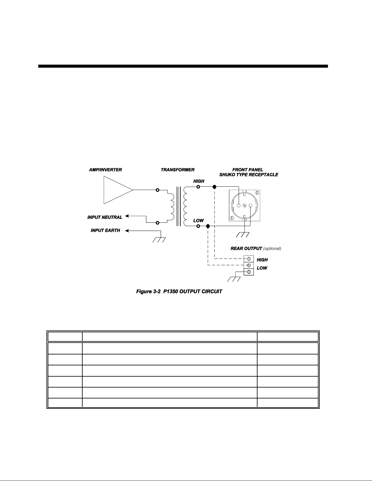
3.2 CONNECTING LOADS
The load is connected to the front panel “SHUKO” receptacle or optional rear panel terminals. Several
adaptors are available to mate with various international line cords. Table 3-2 lists the available
adaptors and their Behlman part numbers. The output circuit of the P1350 AC power supply is
transformer coupled and isolated from the input line power. This allows the unit to float or operate with
eithersideoftheoutputtransformertiedtogroundorotherpotential. Theoutputcircuitconsistsofthree
connections as illustrated in figure 3-2 below. The load is connected between the “High” and Low”
terminals while the third terminal is tied earth via the power supply chassis and input line cord.
3.3 OUTPUT ADAPTORS
Table 3-2 below lists the output adaptors available for the P1350 AC power supply.
OPTION# ADAPTOR DESCRIPTION BEHLMAN P/N
A001 SCHUKO to NEMA 5-15R 107-771-001
A002 SCHUKO to NEMA6-15R 107-771-002
A003 SCHUKO to UK 1-13R 107-771-003
A004 SCHUKO to SWISS SW1-10R 107-771-004
A005 SCHUKO to ITALIAN IT1-10R/16R 107-771-005
A006 SCHUKO to AUSTRALIAN A01-10R 107-771-006
Contact Behlman for any special requirements not listed above.

9
SECTION 3
P1350 AC POWER SUPPLY OPERATING INSTRUCTIONS
3.4 OPERATION UNDER FAULT CONDITIONS.
The P1350 ACsource incorporates three levelsof over currentprotection. Thefirst isa foldback circuit
that reacts to long term RMS over current. In the event that the load applied is outside the range of the
power source, the output voltage will decrease or “fold -back” in order to maintain the current. During
foldbacktheoutputwaveform remainssinusoidal.Thiscanbea usefulfeatureforstartingACinduction
motors and other types of motion related loads.
In the event the load becomes short circuited the amount of fault current could rise to levels high
enough to damage the output semiconductors of the power source. The current of the output stage is
monitored on a cycle by cycle basis at the 20KHz switching frequency. If the peak current exceeds an
unsafe value, a logic signal is sent to the drive circuits that initiates a controlled shutdown of the output
stage. This circuit can respond within 20usec. The action of this overload circuit is latching. The input
powermust becycled toreset thepower source.Allow atleast 20- 30seconds forthe internalsoftstart
circuit to reset. Further information is provided in this manual under operating considerations.
The final form of protection is provided by a 25 amp input fuse. This fuse is employed primarily to
providefireprotection intheevent ofan internalfailure ofthe powersource. Failureof thisfuse typically
indicates that an internal problem may exist.
! CAUTION
In the event the fuse is to be replaced disconnect power before removing the fuse cover.
This fuse is rated at 25A and 132V minimum and must be replaced with the same type and voltage
rating only! If a replacement fuse blows again the unit should be returned to Behlman for service.
3.5 TROUBLE SHOOTING
In the event a problem is encountered refer to the chart below :
PROBLEM POSSIBLE CAUSE
No output, meter indicates 000 Adjust output control, check if overload latch LED is on. See section 4.
Load does not operate, unit
indicates desired output. Check that load is switched on. Check that the load is connected between HI and
Lo output terminals vs. HI and GND. terminals. See section 3.2.
Output voltage drops when load
is connected. Check load current to insure that the rating of the power supply is not exceeded.
This may be indicated by a “blinking” or steady constant current LED.
Output drops to zero when load
is connected, Overload LED is
on.
Load in-rush or surge current has exceeded the short circuit limit for the power
supply. See section 4 for techniques to limit in-rush current.
Unit is Dead, no display or fan
sound. Blown input fuse. Check and replace per para.3.4. If fuse blows repeatedly ,
remove unit from use and refer to qualified service personnel or Behlman service
dept.

10
SECTION 4
P1350 AC POWER SUPPLY OPERATING CONSIDERATIONS
OPERATIONAL CONSIDERATIONS
4.1 OPERATION INTO LINEAR LOADS
The model P1350 will provide the best overall performance into a linear load. A linear load is
characterizedby thatfactthat itscurrentwaveshape issinusoidal. Thephase relationshipbetween the
voltage and current may be anything between zero and 90 degrees (leading or lagging). Some
examples of linear loads are as follows:
Most AC Motors, Power Transformers, Heating Elements, Resistors, Capacitors, Most Inductors
Incandescent Lighting ( without dimmers ), and Most Solenoids
Operation into these types of loads usually causes little interaction with the output stage of the model
P1350. The main concern with a linear load is the “inrush” current associated with it. Most heating
elements and resistors have no in rush concerns and usually do not present any problem for the power
source. Inductive and capacitive loads may present a special problem based ontheir construction and
the way in which they are energized. Motors and tungsten filament lamps also present some special
“start-up” concerns. The following is intended to give the end user some insight into applying the AC
source to these types of loads.
4.2 DRIVING REACTIVE LOADS
Capacitors and inductors are reactive in nature. If the load is applied during the peak of the AC cycle
there may be a considerable inrush of current several magnitudes larger than the steady state current.
This current is only limited by any series resistance that may be present in the load circuit. Under the
rightconditions,thiscouldtriptheoverloadprotectioncircuitsinthepowersource.Certaintransformers
and solenoids (inductance) present the same problem.
Several methods can be used to prevent tripping the protection circuits in the power source. One
common method is to insert a limiting impedance in series with the load. This could be a fixed resistor
or NTC (negative temperature coefficient) thermistor. Also, zero crossing switching can be employed.
The most obvious way to prevent a high in rush current is to apply the load with the voltage set to zero
(or some low value) and energize the load slowly by turning up the voltage.
4.3 DRIVING LAMPS
Tungsten filament lamps, when cold, present a very low resistance. Once they are energized, their
resistance quickly climbs to its steady state value. This characteristic must be accounted for when
driving tungsten filament lamps. The same methods for driving reactive loads can be applied to
tungsten.
4.4 DRIVING MOTORS
Driving an AC motor presents a special problem. Most motors require a starting current that is several
times higher than the running current. This current may last for a few cycles to several seconds
depending on the construction and mechanical load on the motor. This current is sometimes referred
to as the motor’s “locked rotor” current. This current is not to be confused with the in rush current that
usually occurs over the course of one or two cycles of the AC waveform.
The model P1351's fold-back current limiting can be an advantage when starting motors. During the
starting period, the motor will attempt to draw excessive power from the power source. The fold-back
circuit will reduce the output voltage in order to maintain the maximum current for the range in use.

11
SECTION 4
P1350 AC POWER SUPPLY OPERATING CONSIDERATIONS
4.4 DRIVING MOTORS (continued)
During this time the current supplied to the motor will remain sinusoidal, this allows the motor to start
rotating.Oncethe motorreachesit’s normaloperatingspeed it generatestherequired“backEMF”and
the supply current drops off to the nominal “run” current for the motor. Ramping up the voltage to the
motor can reduce the locked rotor current demand. This will allow the AC power supply to start many
types of motors with run currents up to 10 Amps.
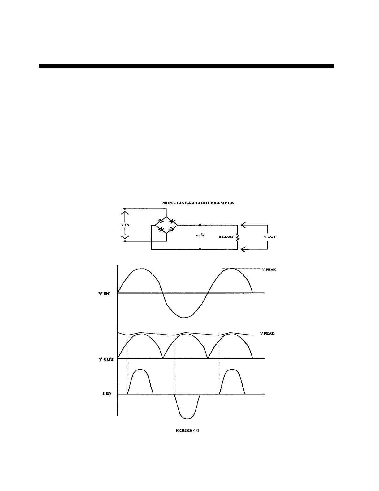
4.5 DRIVING NON-LINEAR LOADS
Loads utilizing rectifiers and SCRs interact with the AC power source and have a profound effect on
the distortion of the output waveform. Consider the use of a bridge rectifier followed by a capacitive
filter. The current waveform associated with this circuit is illustrated in figure 4-1. The input current to
this type of circuit is drawn in large “gulps” whenever the voltage across the capacitor falls below the
peak of the input waveform. This current is limited only by the series impedance present in the wiring
andcapacitor.Theimpedanceoflargeelectrolyticcapacitorsisverysmall.Thisactioncausesacurrent
waveformwithapeakvaluethatmaybeseveraltimestheRMSvalue.ThisratioofpeakcurrenttoRMS
current is known as “Crest Factor”. High values of crest factor cause distortion of the AC voltage
waveform.
Theamountofdistortionincurredisdependantonmanyfactorsandisbeyondthescopeofthismanual.
It should be noted that this type of load may cause the output waveform to exhibit “flat-topping” This
should not be associated with a defect of the power source. Most “real world” electric distribution
systems exhibit this distortion for this reason.
4.6 INPUT POWER REQUIREMENTS
The model P1350 utilizes a rectifier followed by a bank of filter capacitors. Because of this fact, it
presents a nonlinear load to the utility power. The’s input current waveform has a high crest factor and
contains a large amount of harmonic currents.These harmonic currents do not contribute to the output
power of the power source but must still be supplied by the input line. This adds up to a poor input
power factor.
!WARNING
When selectinga suitablelineinput, it mustbeunderstood thattheinput currentrequiredfor fulloutput
power (1350 watts) from the P1350 may exceed 20Amps RMS. This is only true for purely resistive
loads (Watts v.s. Volt/Amperes). For this reason the unit is supplied with an IEC 320 C-20 input
receptacle. If continuous full power operation is desired, the unit must be supplied from the equivalent
20 amp-rated receptacle. The line cord (P/N 107-802-000) supplied with the unit has standard North
American NEMA 15P at one end. This was done due to the fact that it is more convenient to most end
users. Although the cord itself can handle the current, the line end should be changed to the
appropriate mate for prolonged full power operation. Failure to do so may cause overheating of the
input line connection. This may cause a fire hazard. Consult with Behlman if unsure.
Full power operation into a full resistive load may cause loading ( sagging )of the supplied line voltage
if a large series impedance is present. This is due to the high current required by the model P1350. If
problems are encountered while trying to achieve full output power, monitor the input line. If the line
drops below 110VAC, move the unit to a known “stiff” line.
12
SECTION 4
P1350 AC POWER SUPPLY OPERATING CONSIDERATIONS
4.7 OUTPUT NOISE
Because the model P1350 uses a high frequency PWM conversion technique, a certain amount of
outputnoiseorrippleis tobeexpected.Thenoisepresentontheoutputvoltagewaveformfromthisunit
variessomewhatwiththeload. Maximumnoiselevelsarepresentwhenthereisno loadapplied.Inany
event, the amount of noise present should not constitute a problem for properly designed equipment.
If the devices being tested are disabled by the noise present on the output waveform, then serious
considerationshould be givento the designof the unit beingtested asthey maynot passthe European
EMI tests.
In special cases where the output noise is objectionable or interfering with low level measurements
an external line filter can be added to the output of the unit. Please note that most line filters are not
intendedtobe usedat400Hz. Radiatedoutputnoise mayreduced by usingshielded outputwiring. The
shield can be terminated to the GND terminal of the AC supply . This connection should be as short
and direct as possible.
13
RANGE
LOW
HIGH
VOLTS
FAULT
%(+/0$1
Power Passport
50 Hz 60Hz 400 Hz
FREQUENCY
SECTION 4
P1350 AC POWER SUPPLY OPERATING CONSIDERATIONS
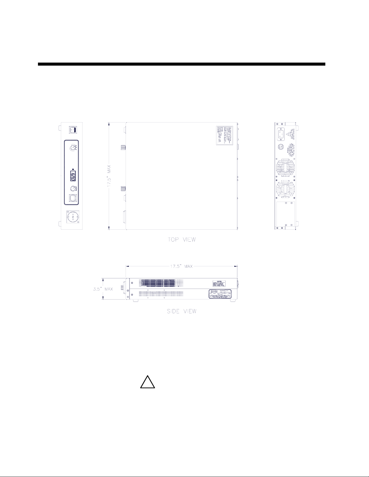
4.8 MECHANICAL OUTLINE
The figure below illustrates the mechanical configuration of the P1350 AC power supply. This view
does not show the RM option rack mounting kit.
4.9 RACK MOUNTING ( OPTION RM )
The RM option kit is supplied for units that are to be mounted in a standard EIA equipment rack. This
kit includes two mounting brackets and associated hardware. The brackets are attached to the left and
right side panels using existing threaded inserts and the supplied screws.
!WARNING
DO NOT substitute longer screws as these may damage internal parts and create a shock
hazard. Note that these brackets are intended to secure the front panel to the rack only. Due to the
weight of this device rear support must be provided by the equipment rack. Do not rely onRM brackets
only.

14
SECTION 5
P1350 AC POWER SUPPLY OPTIONS
The P1350 series of AC power supplies is available withseveral options.These can bespecified at the
time of purchase or addedas required by end user. Table 5-1 below listed the availableoptions for this
model series. Behlman also produces modified versions of this unit that may be application specific.
These units will be assigned a 4 digit “engineering” number. Any information required for operation will
be added to this manuals as an addendum.
OPTION DESCRIPTION PART #
A001 output adapter “SCHUKO” to NEMA 5-15R 107-771-001
A002 output adapter “SCHUKO” to NEMA 6-15R 107-771-002
A003 output adapter “SCHUKO” to UK 1-13R 107-771-003
A004 output adapter “SCHUKO” to Swiss SW1-10R 107-771-004
A005 output adapter “SCHUKO” to Italian IT1 - 10R/16R 107-771-005
A006 output adapter “SCHUKO” to Australian A01-10R 107-771-006
RM EIA rack mounting bracket kit. 107-822-000
TB * Rear output terminal block option. This is connected in parallel with
the front panel SCHUKO socket. HI, LO, and GND provided. 107-821-001
RO *Rear panel NEMA 5-15R added to rear panel. 107-821-000
LC001 Line Cord : IEC-320-C20 to NEMA 15P 107-802-000
LC002 Line Cord: IEC-320-C20 to NEMA 5-20P 107-802-002
L Locking device fitted to front panel VOLTS control. N/A
4065 * 0- 10VDC remote control of output voltage P1350 -4065
* Note: options TB, RO, and 4065 are not considered field installable options and must be factory installed .
Call a Behlman Sales representative for pricing and further information.

15
SECTION 5
P1350 with ANALOG REMOTE CONTROL OPTION - 4065
1.0 INTRODUCTION
This option provides a means of controlling the model P1350 output voltage with a 0-10Vdc analog
signal.In addition, thepower supply's outputrange may be set to the high range via a digital input. This
interface provides complete isolation from ground and the power stage of the power supply. An
additional terminal block is fitted to the rear of the power supply chassis.
2.0 SPECIFICATIONS
0 To 10VDC Control Input Impedance ............................ 10K ohms minimum
Maximum Input Voltage ................................................+/- 15 Vdc
Control Input to Output Linearity ...................................... 1% typical
Control Response Time .....................................................250mS typical
Isolation Voltage ................................................................500 Vdc ( 300 Vac 60Hz )
3.0 CONTROL TERMINAL ASSIGNMENT ( TB-1 )
POS. PIN NAME FUNCTION
TB1-1 VOLTAGE CONTROL 0-10VDC input control output ac voltage.
TB1-2 COMMON signal return for dc control
TB1-3 RANGE + 8 - 15 VDC set range to 0-270V
TB1-4 RANGE - 8 - 15VDC signal return
APPLICATION INFORMATION
To use the remote control features the front panel VOLTS controls MUST BE set fully counter
clockwise. The RANGE switch must be set to the "LOW" position. Note that the remote input is
additive and will increase the setting of the front panel controls.
Cables used to connect the control circuit to the power source should be shielded to prevent noise
and electromagnetic interference from entering the remote inputs. A shielded twisted pair is
recommended. Cable shields should be terminated at the control side of the circuit. The maximum
lengthofthese cablesisdependent onthecontrol circuit’sdrivecapability.It shouldbenotedthat some
IC output stages may become unstable and oscillate when driving long cables with high capacitance.
Low output impedance buffers should be considered when long cable lengths are desired.
Thestabilityandregulationofthe P1350outputvoltagewillbedirectlyaffectedbythequalityoftheuser
supplied control signals. This must be considered during the design of the control circuitry.
Table of contents
Other BEHLMAN Power Supply manuals

BEHLMAN
BEHLMAN P1351 Use and care manual

BEHLMAN
BEHLMAN BL20000 Series Use and care manual

BEHLMAN
BEHLMAN BL10000 Series Use and care manual

BEHLMAN
BEHLMAN BL3300 Series Use and care manual

BEHLMAN
BEHLMAN PF1350 Series Use and care manual

BEHLMAN
BEHLMAN BL5000 Series Use and care manual

BEHLMAN
BEHLMAN PF1352 Series User manual

BEHLMAN
BEHLMAN BL15000 Series Use and care manual


