Et system ELP/DCH Series User manual

1
User’s Manual
ELP/DCH series
PROGRAMMABLE DC ELECTRONIC LOAD
ET System electronic GmbH 2021-06-10 Manual Edition V.2.2

ET System electronic GmbH
2
Content
Contents Introduction.........................................................................................................................................4
Chapter 1 Size and Installation...........................................................................................................................8
1 .1 Dimension ..............................................................................................................................................8
1.2 Installation.............................................................................................................................................10
1.3 Plug in Power Cord ...............................................................................................................................10
Chapter 2 Quick Start.......................................................................................................................................11
2.1 Product Introduction..............................................................................................................................11
2.2 Features .................................................................................................................................................11
2.3 Front Panel ............................................................................................................................................13
2.4 LCD Status Bar Function ......................................................................................................................14
2.5 Rear Panel .............................................................................................................................................16
2.6 First turn-on checkout ...........................................................................................................................16
2.6.1 Self-test Process.....................................................................................................................17
2.6.2 In the Event of a Problem......................................................................................................17
Chapter 3 Functions and Features .......................................................................................................................19
3.1 Basic Operation Modes ......................................................................................................................19
3.1.1 Constant Current Mode (CC)................................................................................................20
3.1.2 Constant Voltage Mode (CV) ................................................................................................21
3.1.3 Constant Resistance Mode (CR)..........................................................................................22
3.1.4 Constant Power Mode (CW) .................................................................................................23
3.2 List Operation........................................................................................................................................24
3.3 OCP Test Function.................................................................................................................................27
3.4 EFFT Function ......................................................................................................................................29
3.5 Auto test function ..................................................................................................................................30
3.6 Dynamic Function .................................................................................................................................35
3.7 Battery test function ..............................................................................................................................39
3.8 Short-circuit Simulation Function .........................................................................................................41
3.9 LED Simulation Function .....................................................................................................................42
3.10 SWEEP dynamic frequency conversion scanning...............................................................................46
3.11 TIMING Time measurement ............................................................................................................48
3.12 DCR DC Resistance Measurement Function ...................................................................................50
3.13 Measurement item ............................................................................................................................52
3.13.1 Voltage, current, resistance and power measurement ...................................................52
3.13.2 Ripple measurement............................................................................................................53
Chapter 4 System settings and Save function......................................................................................................54
4.1 System Settings .....................................................................................................................................54
4.1.1 Von/Voff Function....................................................................................................................55
4.1.2 Source Type Selection Function...........................................................................................56
4.2 Configuration ........................................................................................................................................56
4.2.1 Remote Sense Compensation Mode...................................................................................58
4.2.2 Shortcut Call Mode.................................................................................................................59
4.2.3 Trigger Output Settings..........................................................................................................60
4.3 Save/Recall Function ............................................................................................................................60
Chapter 5 Protection Function.............................................................................................................................62
5. 1 Over-voltage protection (OVP) ............................................................................................................62
5.2 Over-current protection (OCP)..............................................................................................................62
5.3 Over-power protection (OVP)...............................................................................................................63
5.4 Over-temperature protection (OTP) ......................................................................................................63
5.5 Input Voltage Reverse Protection (RV) .................................................................................................64
Chapter 6 I/O Interface........................................................................................................................................65
6.1 I/O Interface .......................................................................................................................................65
6.2 I/O Interface Function ........................................................................................................................65
Chapter 7 Specifications...................................................................................................................................67
7.1 Main Specifications...............................................................................................................................67
Chapter 8 Communication Interfaces..................................................................................................................77
8.1 Communication module ........................................................................................................................77

3
8.2 DB9 .......................................................................................................................................................77
8.3 Protocol .................................................................................................................................................78
8.4 SCPI Communication Instruction .........................................................................................................79
ET System electronic GmbH

4
Contents Introduction
Thank you for purchasing ELP/DCH series DC Electronic Load. To obtain maximum
performance from the product, please read this manual first, and keep it handy for future reference.
We will use the alias E-load of DC Electronic Load in the following.
Registered trademarks
Windows and Excel are registered trademarks of Microsoft Corporation in the United States and/or
other countries.
Checking Package Contents
When you receive the instrument, inspect it carefully to ensure that no damage occurred during
shipping. In particular, check the accessories, panel switches, and connectors. If damage is evident,
or if it fails to operate according to the specifications, contact your authorized Hopetech distributor or
reseller.
When transporting the instrument, use the same packaging materials used for the delivery to you.
Check the package contents as follows
No.
Item
Quantity
1
Electronic Load
1
2
User’s Manual
1
3
RS232 Cable
1
4
Power Cord
1
5
Test Report
1
Safety Notes
The instrument is designed to conform to IEC 61010 Safety Standards, and has been thoroughly
tested for safety prior to shipment. However, using the instrument in a way not described in this
manual may negate the provided safety features.
Before using the instrument, be certain to carefully read the following safety notes.
Note
Mishandling during use could result in injury or death, as well as damage to the instrument. Be certain
that you understand the instructions and precautions in the manual before use.
Notation
This manual contains information and warnings essential for safe operation of the instrument and for
maintaining it in safe operating condition. Before using the instrument, be certain to carefully read the
following safety notes.
ET System electronic GmbH
5
Indicates very important message in this manual. When the symbol is printed
on the instrument, refer to a corresponding topic in the Instruction Manual.
Indicates DC (direct current)
Indicates a fuse
Indicates earth terminal
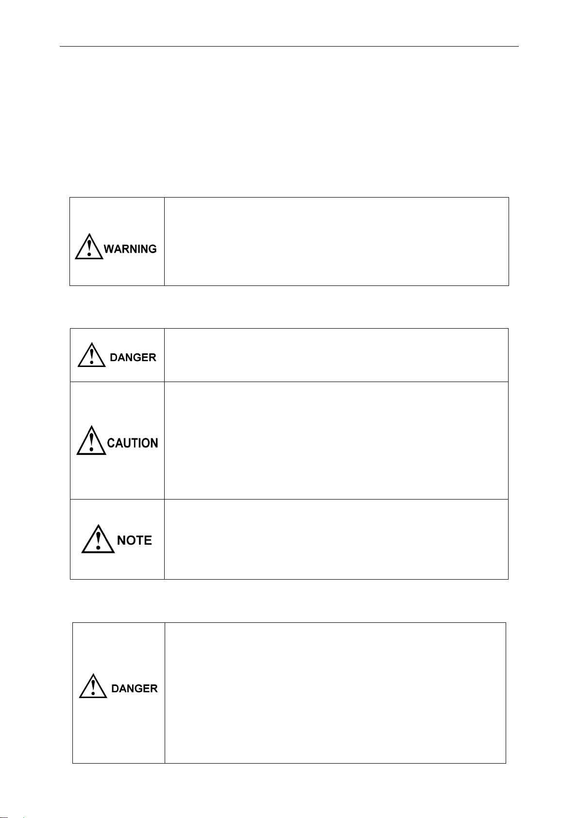
In this manual, the risk seriousness and the hazard levels are classified as follows.
Indicates an imminently hazardous situation that will result in death or
serious injury to the operator.
Indicates a potentially hazardous situation that will result in death or serious
injury to the operator.
Indicates a potentially hazardous situation that may result in minor or
moderate injury to the operator or damage to the instrument or malfunction.
Indicates functions of the instrument or relative suggestion of a correct
operation.
Usage Notes
Installation environment
Operating temperature and humidity range
0°C ~ 40°C,< 80%RH(no condensation)
Storage temperature and humidity range
23 ±5°C,< 80%RH (no condensation)
Installing the instrument in inappropriate locations may cause a malfunction of instrument or accident.
Avoid the following locations.
Exposed to direct sunlight or high temperature
Exposed to corrosive or combustible gases
Exposed to water, oil, chemicals, or solvents
Exposed to high humidity or condensation
Exposed to a strong electromagnetic field or electrostatic charge
Exposed to high quantities of dust particles
ET System electronic GmbH
6
Near induction heating systems (such as high-frequency induction heating systems
and IH cooking equipment)
Susceptible to vibration
Checking before use
Before using the instrument at the first time, verify that it operates normally to ensure that no damage
occurred during storage or shipping. If you find any damage, contact your authorized Hopetech
distributor or reseller.
Before using the instrument, check that the coating of the test leads or
cables are neither ripped nor torn and that no metal parts are exposed.
Using the instrument under such conditions could result in electrocution.
Contact your authorized Hopetech distributor or reseller in this case
Handling Precautions
Do not try to modify, disassemble, or repair the instrument. This may result
in fire, electric shock accident, or injury.
Do not place the instrument on an unstable or slanted surface. It may drop
or fall, causing injury or instrument failure.
This equipment is an electric energy conversion to heat equipment,
blocking the ventilation holes of the equipment will lead to serious
consequences.
Be sure to turn the power off after using it.
Measurement precautions
To avoid electric shock accident and short circuit, please operate the
instrument as following:
Do not test the voltage over 150 VDC
Do not test the terminal-to-ground voltage over 160 VDC.
Do not test AC voltage.
ET System electronic GmbH

7
Be sure to connect the test lead correctly.
Wear gloves of rubber or similar materials during measurement.
For achieving the measurement accuracy, it is recommended that the
equipment should be operated half an hour after power-on.
ET System electronic GmbH

8
Chapter 1 Size and Installation
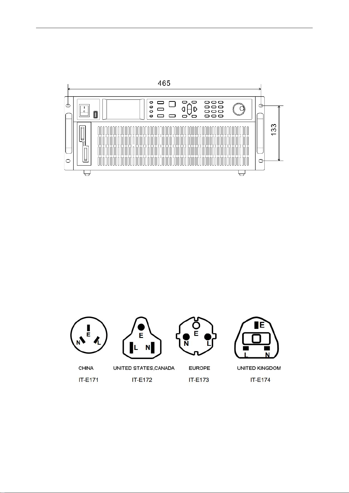
1 .1 Dimension
ELP/DCH series electronic load dimension
Figure 1.1 Appearance of instrument
ET System electronic GmbH

9
Figure 1.2 Instrument dimension 1
Figure 1.3 Instrument dimension 2
ET System electronic GmbH
10
1.2 Installation
This instrument is intended for indoor use in a pollution degree 2 environment. Please refer to the
specifications table for the allowable environment operating limits.
Figure 1.6 E-Load outline diagram (unit mm)
There are 2 cabinet mounting holes on the both sides of the E-load. After removing the gap, it can be
used for cabinet installation and positioning.
1.3 Plug in Power Cord
Connect an appropriate IEC power cord to the DC Load and plug the power cord into an AC power
outlet. Please find the following power cord type in different countries and areas.
Ensure that the line voltage selector switch on the back panel is set to match your line voltage. Failure
to do so could result in damage to the instrument.
Figure 1.7 4 types of power cord for different countries and area
ET System electronic GmbH

11
Chapter 2 Quick Start
This chapter describes the power-on check procedure for the ELP/DCH Series load to
ensure that the E-load is properly started and used during initialization. It also
introduces the E-load front panel, rear panel, keyboard button functions and LCD
display function to ensure that you can quickly understand the appearance, structure
and button usage of the E-load before operating the E-load.
2.1 Product Introduction
With dynamic, automatic test, LED, List, OCP, EFFECT, battery and short and many other
test functions, ELP/DCH series E-load is mainly used for battery, AC-DC, DC-DC
modules, chargers and electronic components and other product performance testing. It
provides a best solution for design development and production line testing.
ELP/DCH series E-load supports RS232, RS485, and Ethernet communication interfaces
to fit your versatile solution and testing needs.
2.2 Features
1) 24-bit true color LCD display (liquid crystal display), GUI operation interface;
2) 500kHz synchronous sampling, 10Hz, 0.1mV/0.01mA stable resolution output;
3) Four basic function modes:
CV constant voltage mode
CC constant current mode
CW constant power mode
CR constant resistance mode
4)Multiple extended function modes:
LIST mode
ET System electronic GmbH

12
simulate a variety states of load change.
OCP mode
Over current protection point test mode.
EFFECT mode
Load effect test mode.
AUTO mode
5) Actual LED simulation to test LED power.
6) Voltage/current ripple test (Vpp, Ipp );
7) Professional battery test function (BATTERY);
8) Dynamic Test Mode (DYNA);
9) High-speed dynamic frequency conversion scanning function (SWEEP)
10) Short circuit mode (SHORT);
11) Shortcut mode supports 10 sets of global data storage and reading (SHORTCUT);
12) No loading mode (OFF);
13) Support Von and Voff functions;
14) Remote compensation measurement mode (REMOTE);
15) Memory capacity up to 200*8 groups;
16) Intelligent fan system fan automatically initiated activate according based on changing
to the ambient temperatures
17) Built-in Buzzer as an early warning reminder;
ET System electronic GmbH
13
18) Power-off to maintain memory function;
19) USB port upgrade procedure;
20) Electrically isolated communication for I/O interface, RS232/485, NET network port;
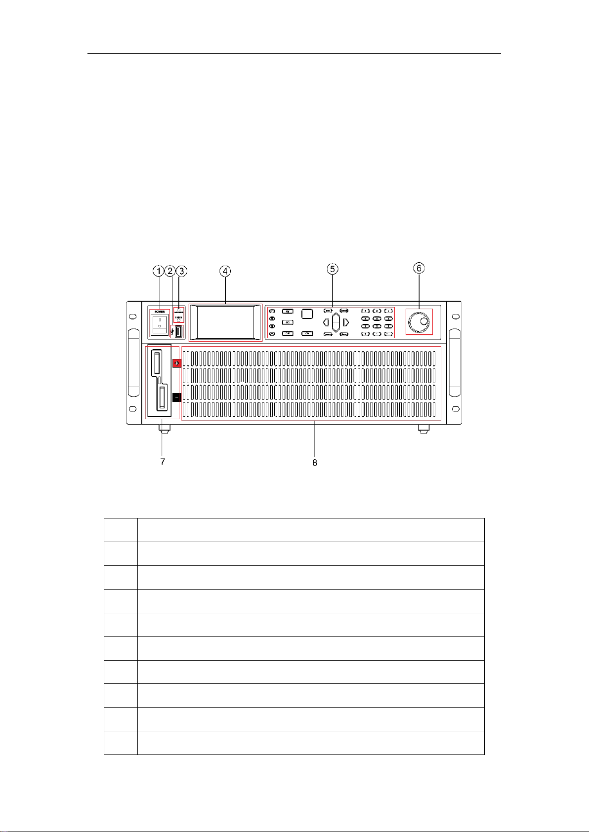
2.3 Front Panel
The following picture is the front panel for the ELP/DCH E-Load. All models have the
same front panel, only the terminal section will vary based on the model.
Figure 2.1 front panel
Item
Description
1
Warning lights for loading failure or other warning states
2
U disk interface
3
Power-up key
4
Function keys
5
E-Load input terminal
6
Operating keys
7
Digital keys
8
Operating keys
9
LCD display panel
ET System electronic GmbH

14
10
SENSE Remote compensation port
Front panel key description
When in the standby state, the panel POWER button light is red,
press the POWER button for 3s, the power is turned on, the screen is
lit, and the panel button light turns green.
In the working mode, press the key SET to set the parameters
corresponding to the mode.
Long press to open/close the keyboard lock;
when the status bar icon is , all other keys are invalid.
When the E-load is in the working mode, press this key to select the
expected load modes.
Press this key to switch the interface between load, system
configuration, system parameter setting and loading the setting files.
In the working mode interface, adjust the cursor position and adjust
the loading value. Move the status bar position on another interface.
Trigger the E-load in specific working mode
Confirm the selected value or enter the setting menu.
Cancellation of operation or moving back to the top menu.
Loading or unloading the load.
4 basic working modes(CV/CC/CW/CR) shortcut keys.
11 digital keys and is backspace key
2.4 LCD Status Bar Function
The following screen is ELP/DCH series E-oad LCD display interface.The status bar is
the top line icons. There are several icons on the status bar in the top line.
ET System electronic GmbH

15
Figure 2.2 LCD interface
Item
Description
1
Instrument operating mode and status bar (described in the below table);
2
Readback value display
3
Present loading value edit box
4
E-load protection limit setting
5
E-load conversion parameter value display
Status bar icon description
The remote compensation function is turned on.
Through the SENSE port at the rear panel of E-load, the output
voltage of the power supply under test is collected.
Using remote sensing, you can sense the voltage at the power
supply's terminals, effectively removing the effect of the voltage drop
in the connection wire.
Loading automatically while start setup voltage > VON voltage
Stop loading while shutdown voltage < Voff voltage
Shortcut mode is on
Keyboard lock.
Icon is , keyboard locks, long press to unlock.
ET System electronic GmbH

16
means E-load connecting to the PC, it is allowed to Send
commands on the PC to perform related operations on the E-load.
2.5 Rear Panel
The following picture is the rear panel for the ELP/DCH E-load.
Figure2.3 Rear panel
Item
Description
1
Cooling holes
2
0 to full-scale current, corresponding to 0-10V output, can be connected
to the oscilloscope
3
Hardware Power button
4
Power inlet ( AC 100~240V input)
5
LAN communication port
6
SENSE port for voltage sense compensation
7
DB9 communication interface, RS232/485
8
I/O interface connector, this I/O interface need to be powered by external
power
2.6 First turn-on checkout
The successful self-test process indicates that the E-load meets the factory standards and
ET System electronic GmbH

17
can be used by the user normally. Before operating the E-load, make sure you understand
the safety instructions.
Ensure that the line voltage selector switch on the back panel is
set to match your line voltage. Failure to do so could result in
damage to the instrument.
Connect an appropriate power cord to the E-Load and plug the
power cord into an AC power outlet. Ensure that nothing is
connected to the INPUT terminals.
Before operating the E-load, ensure it is well grounded.
To prevent damaging the E-load, please pay special attention to
positive and negative polarities of E-load during connection!
2.6.1 Self-test Process
The standard E-load self-test process is as follows:
1) Connect an appropriate IEC power cord to the E-load and plug the power cord into an
AC power outlet. Press the hardware power button at the back panel. At this time, soft
power switch button lights up red in the front panel, long press the soft power switch to
power on the instrument.(if the E-load using soft power switch button)
2) After the E-load initialization completed, the LCD display shows the working mode
information.
Figure 2.4 CV Work mode interface
2.6.2 In the Event of a Problem
If the E-load fails to power up, the following troubleshooting steps will help you to solve the
ET System electronic GmbH

18
problem.
1. Make sure the power cord is connected properly and the power switch has been
pushed in to ON.
Go to step 2 ---- when the power cord is well connected
Back to step 1----- when the power cord is wrongly connected
2. Check the hardware Power button at the back panel in ON state and the soft Power
Switch at the front panel is lit red.( if the E-load using soft power switch button )
Go to step 3--- YES
Press the Power button to turn on the instrument and to see if the exception is
cleared------NO.
3. Check whether the voltage of power supply is larger than the rated voltage of the
equipment.
ET System electronic GmbH

19
Chapter 3 Functions and Features
This chapter will introduce functions and features of ELP/DCH E-load in the following
sections:
Basic operation modes
LIST function
OCP over current test function
EFFT load effect test function
AUTO automatic test function
DYNA dynamic test function
BATT battery test function
SHORT short-circuit simulation function
LED load simulation function
SWEEP dynamic frequency conversion scanning function
TIMEING time measurement function
DCR DC resistance measurement function;
Measurement items
3.1 Basic Operation Modes
The E-load has four basic modes:
1) Constant current mode (CC)
2) Constant voltage mode (CV)
3) constant resistance mode (CR)
4) Constant power mode (CW)
ET System electronic GmbH
20
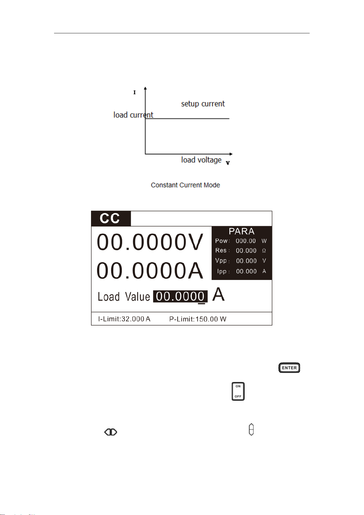
3.1.1 Constant Current Mode (CC)
In constant current mode, the DC E-load will sink a constant current, regardless of the
voltage of the source. See the figure below.
Figure 3.1 CC mode
In CC mode, the E-load provides two methods to set the constant current value.
1) In CC mode, use the numeric keys to input the current value, press the key to
confirm the setup constant current value, and press the key to load or unload the
source.
2) Press the key to move the cursor position and press the key to adjust the value
at the corresponding position.
ET System electronic GmbH
This manual suits for next models
18
Table of contents
Other Et system Power Supply manuals


