Etalex E Series User manual
E SERIES INSTALLATION MANUAL

02
ETALEX.CA
Installation / E Series
ASSEMBLAGE
Highly practical and robust, the E Series has been
designed to shine a long time. With its unique post
and solid or perforated metal backs, this model
provides added structural strength. Our E Series,
renowed for its lasting durability, can be moved
without being completely emptied. Choose the color
you want, the configuration of the shelving system,
the accessories and there you go!
TECHNICAL SPECIFICATIONS
Post height: 48’’- 120’’ (In increments of 6’’)
Base shelf: 6’’- 30’’ deep (In increments of 2’’)
Width: 24’’- 48’’ (In increments of 6’’)
Rear back options:
Metal (plain or Perforated), wire mesh & Slatwall
Base shelf height:
7 1/4’’ H. (from floor to the top of the base shelf)
E SERIES

04
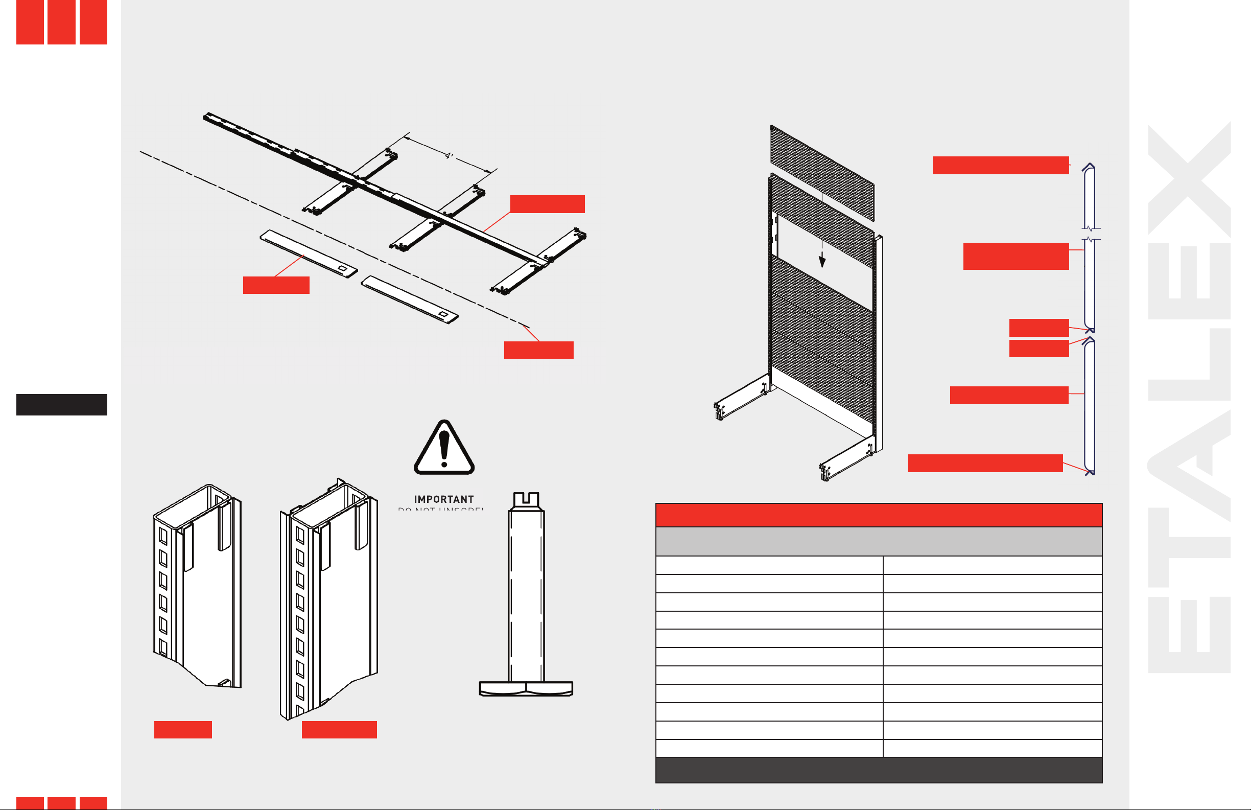
EXPLODED VIEW
ETALEX.CA
Installation / E Series
COMPONENTS
BRACKET
HD END POST (UPRIGHT)
HD CENTER POST (UPRIGHT)
LEFT SHOE
COVER
KICK PLATE
PLAIN METAL BACK
7 1/4“ H
SHELF
RIGHT SHOE
COVER
TOP CAP
PERFORATED
METAL BACK
14 1/2“ H
GONDOLA
PART LIST
ITEM QTY DESCRIPTION
1 2 HD END POST
(UPRIGHT)
2 6 BRACKET
3 14 SHELF
4 2 LEFT SHOE COVER
5 2 RIGHT SHOE COVER
6 2 KICK PLATE
7 1 TOP CAP
8 2 PLAIN METAL BACK 7
1/4“ H
9 10 PERFORATED METAL
BACK 14 1/2“ H
WALL UNIT
PART LIST
ITEM QTY DESCRIPTION
1 2 HD END POST (UPRIGHT)
2 3 BRACKET
3 4 SHELF
4 1 LEFT SHOE COVER
5 1 RIGHT SHOE COVER
6 1 KICK PLATE
7 1 TOP CAP
8 1 PLAIN METAL BACK
7 1/4“ H
9 5 PERFORATED METAL
BACK 14 1/2“ H
11 1 WALL ANCHOR BAR 48“
12 4 PAN SOCKET SCREW
NO8 X 1“ L
06
ETALEX.CA
Installation / E Series
ASSEMBLYASSEMBLY
TRACE A CHALK LINE ON THE FLOOR FOR DESIRED LOCATION OF GONDOLA.
LAY DOWN THE HD END POSTS UPRIGHTS AND THE KICK PLATES ALONG THE CHALK LINE.
FIRST, SLIDE IN THE 7 1/4“ H METAL BACK FOLLOWED BY THE 14 1/2“ H METAL BACK.
PLACE IN THE WELDED STRIP OF THE END POST. ON BOTH THE FRONT AND REAR OF THE
HD END POST UPRIGHT. SEE THE GRID OF CHART POSTS VS BACKS.
METHOD OF INTERLOCKING THE BACK PANELS
ADJUST THE LEVELERS
APPROXIMATELY AT 1/2“.
CHALK LINE
KICK PLATE
HD END POST
PLAIN BACK 7 1/4“H
CONCAVE EDGE FACING DOWN
NOTE:
START WITH THE END POST, THEN THE CENTER POST
AND CONCLUDE WITH AN END POST.
NOTE:
THE HORIZONTAL
EDGE OF THE
PLAIN AND
PEFORATED
BACK PANELS
HAVE A CONVEX
AND CONCAVE
HORIZONTAL
EDGE. MAKE
SURE THE
CONCAVE EDGE
IS FACING THE
BOTTOM WHEN
YOU SLIDE THE
PANEL DOWN THE
WELDED STRIP.
REPEAT THE SAME
PROCESS FOR
EACH PANEL TO
ENSURE A TIGHT
FIT.
END POST CENTER POST
IMPORTANT
DO NOT UNSCREW
THE LEVELERS
MORE THAN 1 1/2“.
IMPORTANT
IMPORTANT
DO NOT UNSCREW
DO NOT UNSCREW
CHART FOR POSTS VS BACKS
NUMBER OF 14 1/2“ WALL AND/OR PLAIN BACK 7 1/4“
REQUIRED FOR DIFFERENT POST HEIGHTS.
108” 7 x 14 1/2”
96” 6 x 14 1/2” + 1 x 7 1/4”
90” 6 x 14 1/2”
84” 5 x 14 1/2” + 1 x 7 1/4”
78” 5 x 14 1/2”
72” 4 x 14 1/2” + 1 x 7 1/4”
66” 4 x 14 1/2”
60” 4 x 14 1/2”
54” 3 x 14 1/2” + 1 x 7 1/4”
52” 3 x 14 1/2” + 1 x 7 1/4”
48” 3 x 14 1/2”
*NOTE: THE PLAIN BACKS 7 1/4“H MUST BE INSTALLED FIRST AT THE BASE.
CONVEX EDGE FACING UP
PERFORATED OR
PLAIN BACK 14 1/2“
CONCAVE
CONVEXE

08
ETALEX.CA
Installation / E Series
ASSEMBLY ASSEMBLY
WALL ANCHOR BAR
METHODS TO FIX THE BLOCK WALL
THE WALL ANCHOR BAR ARE REQUIRED FOR ALL THE WALL UNITS TO LIMIT THE
DEFLECTION FORWARD. THE WALL ANCHOR BAR IS REQUIRED FOR THE WALL UNIT
72“ AND HIGHER.
IF THE STRUCTURE IS LAYING DOWN ON THE FLOOR, STAND UP THE ASSEMBLY.
LEVEL THE UNIT HORIZONTALY, BY ADJUSTING THE LEVELERS IN THE FRONT
AND IN THE BACK OF THE FEET TO ENSURE THE STRUCTURES ARE LEVELED
AND PLUMB.
INSTALL THE KICK PLATE ON THE FRONT EDGE
OF THE FEET AND INSTALL THE SHELF TO
STABILIZE THE STRUCTURE.
INSTALL ON THE TOP OF STRUCTURE THE TOP
CAP. INSERT THE SHOES COVERS ON THE BASE
FOOT AT BOTH ENDS OF THE SHELVING UNIT,
PLACE THE BRACKETS AND THE SHELVES AT
THE DESIRED HEIGHT.
OTHER OPTION: THE WALL ANCHOR BRACKET FOR EACH POST.
METHODS TO FIX
THE BLOCK
STRUCTURE WITH
WALL ANCHOR
BRACKET
NOTE:
INSTALL WALL
SECTION
LEANING
BACK 1°.
STANDING POSITION
TOP CAP
SHOE COVER
METHODS TO FIX
WOOD SCREW PAN SOCKET
NO8 X 1 1/2” L X 2 WALL ANCHOR
BRACKET
WOOD BLOCK
2“ X 4“
BLOCK
2“ X 4“
CORNER
ATTACHMENT
FOR
CONCRETE
CONCRETE MASONRY
(Bloc of concrete, brick,etc)
WALL WITH
WOOD UNIT
WALL WITH
METAL UNIT
AUTO
THREAD
SCREW IN
SOLID
EQUIPMENT
SELF TAPPING
SCREW FOR
DRY-WALL TO
EACH METAL
UNIT
COMPRESSION
SCREW FOR
EACH WOOD
UNIT
BLOCK
2“ X 4“
BLOCK
2“ X 4“
BLOCK
2“ X 4“
PAN SOCKET SCREW 18 X 1“ L
(ITEM#12)
WALL
ANCHOR BAR
(ITEM#11)
DETAIL C
WALL
SHELF
SHELF
FEET
KICK PLATE
BRACKET
10
ETALEX.CA
Installation / E Series
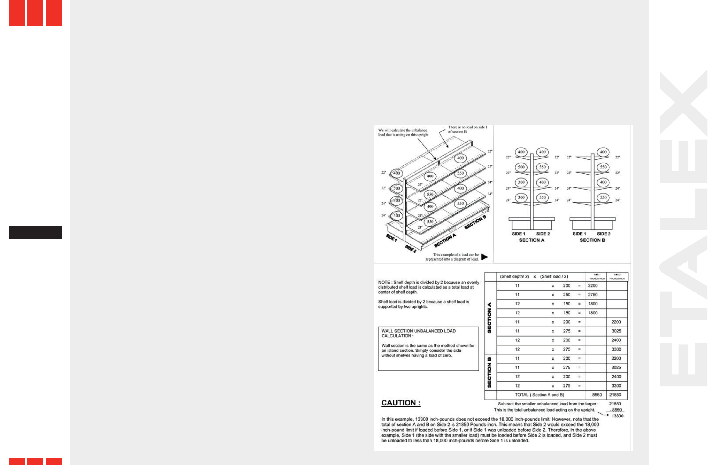
FOR YOUR SAFETY: UNBALANCED LOAD CALCULATION
Install all shelving according to installation instructions.
Assembly or movement of any parts should only be carried out by trained personnel
who have read and understand these instructions and warnings.
Do not use shelving parts or accessories for any purposes other than
originally intended.
Do not combine Etalex products with non Etalex products.
Local codes and regulations concerning building, fire.
Sanitation or seismic requirements may apply to some installations. It is the
responsibility of the buyer of the fixtures to make sure that they are installed in
compliance with any applicable codes and/or regulations.
Do not install damaged parts.
Never after, modify or otherwise structurally change the shelving or any of its
components.
Do not expose any sharp or pointed edges to shoppers or employees.
Never install shelves or accessories onto the side of an upright that has no base
foot to support it.
Be sure all shelving parts or accessories are completely seated in slotting
or perforations.
Do not permit climbing or standing on shelving at any time... including the base shelf.
No shelves or accessories should project past the front of the base shelf.
Do not move an assembled unit, especially if merchandised.
Do not lean heavy items against the shelves.
Provide safe access to all merchandised items in accordance with applicable osha, wcb,
csst regulations.
FOR TECHNICAL ASSISTANCE, CALL ETALEX DIRECT AT 1 - 800 - 351 - 3125.
FOR A WALL SECTION HEAVY LOADED OR WHEN LOADING OR UNLOADING AN
ISLAND. IT IS VERY IMPORTANT TO DETERMINE THAT YOU WILL NOT CREATE AN
UNBALANCED LOAD THAT WILL EXCEED THE LIMIT PERMITTED.
THE EXAMPLE SHOWN BELOW WILL SHOW YOU HOW TO CALCULATE IF YOU HAVE
AN UNBALANCED LOAD IN LBS/INCH.
POUND-INCH IS A MEASURE OF THE SHELF LOADS ACTING AT A DISTANCE FROM
THE UPRIGHT (1/2 THE DEPTH OF THE SHELF).

CONTACT US
ANJOU PLANT
8501, Jarry Street East,
Montreal, QC H1J 1H7
T514 3512000
TF 1 800 3513125
SAINT-BRUNO PLANT
1299, Marie-Victorin,
St-Bruno, QC J3V 6B7
T450 6531299
TF 1 888 224BONI
FACEBOOK/ETALEX
LINKEDIN/ETALEX
YOUTUBE/ETALEX
MADE IN CANADA
WWW.ETALEX.CA
Table of contents
Popular Commercial Food Equipment manuals by other brands


Diamond
Diamond AL1TB/H2-R2 Installation, Operating and Maintenance Instruction

Salva
Salva IVERPAN FC-18 User instructions

Allure
Allure Melanger JR6t Operator's manual

saro
saro FKT 935 operating instructions

Hussmann
Hussmann Rear Roll-in Dairy Installation & operation manual

Cornelius
Cornelius IDC PRO 255 Service manual

Moduline
Moduline HSH E Series Service manual

MINERVA OMEGA
MINERVA OMEGA DERBY 270 operating instructions

Diamond
Diamond OPTIMA 700 Installation, use and maintenance instructions

Diamond
Diamond G9/PLCA4 operating instructions

Cuppone
Cuppone BERNINI BRN 280 Installation

Arneg
Arneg Atlanta Direction for Installation and Use