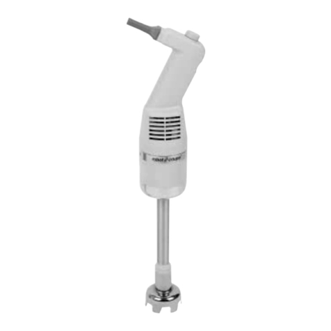
Etatron AF Instructions for use

UNI EN ISO 9001-2008
OPERATINGINSTRUCTIONSAND MAINTENANCE
AF Mixer
UK

1
INDEX
1 HINTS AND WARNING .....................................................................................................................2
1.1 WARNING ..........................................................................................................................................................2
1.2 SHIPPING AND TRANSPORTING THE EQUIPMENT ................................................................................2
1.3 PROPERUSE OF THE EQUIPMENT................................................................................................................2
1.4 GENERAL RECOMMENDATIONS................................................................................................................2
1.5 NOTES FOR SAFETY ........................................................................................................................................ 2
2 INSTALLATION AND START-UP ................................................................................................... 3
2.1 INSTALLATION ................................................................................................................................................3
2.2 START-UP ......................................................................................................................................................... 3
3 PROBLEMS AND COUNTERMEASURES........................................................................................ 5
4 INSTRUCTIONS FOR MAINTENANCE .........................................................................................5
5 DIAGRAM ........................................................................................................................................... 6

2
1 HINTS AND WARNING
1.1 WARNING
Please read the warning notices given in this section very carefully, becausethey provide important
information regarding safety in installation, useandmaintenanceof the mixer.
• Keep this manualin a safeplace, so that it will always be available for further consultation.
• The mixer complies with EEC directives No.89/336 regarding “electromagnetic compatibility” and
No.73/23 regarding “low voltages”, asalso the subsequentmodication No.93/68.
N.B.: The mixer has been constructed in accordance with best practice. Both its life and it
electrical and mechanicalreliability will be enhancedif it is correctly usedand subjectedto regular
maintenance.
WARNING: any intervention or repair to the internal parts of the equipmentmust be carried out
by qualied and authorised personnel. The manufacturers decline all responsibility for the
consequences of failing to respect this rule.
GUARANTEE: 1 year. Improper use of the equipment invalidates the above guarantee. The
guarantee is ex-factory or authorised distributors.
1.2 SHIPPING AND TRANSPORTING THE EQUIPMENT
The mixer should always be moved in a vertical (and never in a horizontal) position. No matter what the
means of transport employed, delivery of the mixer, even when free to the purchaser’s or the addressee’s
domicile, is always at the purchaser’s risk. Claims for any missing materials must be made within 10
(ten) days of arrival, while claims for defective materials will be consideredup to 30th (thirtieth) day
following receipt. Return of mixer or other materials to us or the authorised distributor must be agreed
beforehand with the responsible personnel.
1.3 PROPERUSE OF THE EQUIPMENT
The mixer should be usedonly for the purpose for which it has beenexpressly designed.Any dierent
useis to be considered improper and therefore dangerous.In caseof doubt, pleasecontact our oces for
further information about the characteristics of the mixer and its proper use.
The manufacturers cannot be held responsible for damage deriving from improper, erroneous or
unreasonableuseof the equipment.
1.4 GENERAL RECOMMENDATIONS
Upon receipt of the materials, make sure that no damagehas occurred during the shipment. Notify the
forwarding agentor the supplier, agreeing upon the actions to be taken.
During the handling and transport up to the point of installation, use especially good judgement in the
choice of the hooking points for the hoisting; in particular with regard to the specially covered shafts
(with ebonite, rubber, etc.).
Besidescausing breakage of the covering, eachsmall deformation or impact can modify the alignment of
the shaft with consequent critical vibrations during the operation.
Avoid hoisting the agitators from points of easy rupture such as the terminal boards of the electric
motors, handwheels of adjustable speedmotors, sealow piping, etc.
Possible slings must be passed under the gear box housing unit, and not under the motors. When present,
always usethe hoisting eyebolts, initially checking the correct positioning and testing.
1.5 NOTES FOR SAFETY
Each operation of handling, installation, start-up and maintenancemust be carried out, complying with
the accident prevention laws in force and using every practical expedient for the purposeof safety of the
work expressly mentioned in this text or in the encloseddocumentsof the subordinate suppliers, as well
aseectuating all the proceduresof soundexecution of the work, commonly well-known by the qualied
operators.

3
2 INSTALLATION AND START-UP
2.1 INSTALLATION
- Check the space available for the assembly
- Check that the supporting structure (beams,plates, anges, etc.) hasbeencorrectly sized, taking
the static and dynamic loads producedby the agitator into consideration.
- The anchor bolts must be suitable for the fastening holes (do not use undersized screws) and
must be assembled with plain nut and spring washer.
- Check the presence of baes, when requested, in the cylindrical tanks.
- Check the possibility of inserting the impellers; disassembleand connect to the shaft in the
vesselthrough the pre-arrangedopeningswithout forcing.
- In case of installation in the open,it is necessary that at least the electric motor be protected by a
canopy.
- The motor-gearbox-bearing housing unit normally constitutes a single unit that is to be fastened
to the support structure, observing the torque wrench settings andattending to the level in sucha
way asto guarantee a correct rotation ofthe shaft, free from oscillations that before long could
damage the mechanical stability.
- Make sure that the impellers are assembledin accordancewith the rotation direction and are
fastened rigidly to the shaft. In caseof two or more impellers carried out in various anged
parts, follow the connection of the part’s pre-marked in the factory and tighten the connection
bolts in accordancewith the torque wrench
- Finally, see to the assemblyof all the possible additional elementssupplied separatelysuch as:
- Bushing for steadybearing
- Nut coversfor covering shaft/impeller anges
- Pressure gaugefor pressurisation tank
- Motor protection canopy
2.2 START-UP
Before starting theagitator, it is advisableto carry out the checks described below.
On the motor
Check the connections (bonds on the inside of the terminal board) are arrangedin an exact way and so as
to correspondwith the supply voltage of the of the control line, which must always havethe ground wire.
The entry of the cable into the terminal board must be well insulated and the cover must be screwedwith
care. We recommendthe insertion betweenthe feed line andthe motor of suitably calibrated overload cut
out for the rated current in amperesindicated on the plate.
Without the overload cut out there is no guaranteefor the damage of the winding.
The rotation direction is generally clockwise, viewed from the motor side, and is in any event indicated
by an arrow located on the motor itself. Possibleexceptions to this rule will be specied and the reversal
of the rotation direction canbe obtained by reversing two phases of the feed line amongthem.
On the gearbox
Check the oil level before putting the mixer into operation. The larger gear boxes may be supplied without
oil; in this case seeto the lling with the issuedoil until reaching the maximum level visible from the
special indicator. Sometypes of gear boxes are supplied with un-drilled capsand are supplied with a vent
plug, which must be replaced when installing at the place of the cap, situated in the highest position, in
order to avoid leaks of lubricant caused by the variation of the general internal pressure during the
operation. The gear boxessupplied with permanent lubricant with lifelong grease lack the load, level and
drain plugs.

4
On the variator
Always check the oil level before putting the agitator into operation. Variators are supplied without oil;
in this caseseeto the lling with the issuedoil until reachingthe maximum level visible from the special
indicator.
Sometypes of variators are supplied with un-drilled capsand are supplied with a vent plug, which must
be replacedwhen installing at the place of the cap,situated in the highest position, in order to avoid leaks
of lubricant causedby the variation of the general internal pressureduring the operation. The Variators
supplied with permanentlubricant with lifelong greaselack the load, level anddrain plugs.
- Continuous speed variator is achievedby turning hand wheel.
N.B.: the motovariator must berunning before the adjustment canbe made.
On the impeller
Do not start the agitator if the impeller is immersed in silt, unless this method of operation has been
conditioned in the design phase.
On the entire unit
Check the tightening of all the bolts and nuts. (repeatthe operation after two weeksof operation).
After having carried out above-mentionedinspections, you may proceed with starting the agitator with
the pre-arrangedcontrol devices.
At the beginning of the operation, just as any machine running in, an agitator – causedby the greater
friction’s – can lead to overheating and a higher absorption of current of the motor; these problems
gradually disappearduring the operation.
When a gearbox – cycle converter – is installed, it is generally advisable in time to gradually increasethe
transmitted power, starting from the minimum values,or limiting it (50-70% of the maximum power) for
the rst hours of the operation.
Should an excessive unforeseen absorption occur, disconnect the motor from the power grid, check the
perfect eciency of the contact of the connectionsand check that the working conditions correspondto
those established, especially with regard to the density and viscosity of the liquid; in casethe overload
persists, contact our technical department.
If there are vibrations, stop the agitator immediately and determine the causesthat provoke it.
All the agitators aresuitable for the operation with a maximum and constantlevel; if not foreseenin the
testingphase,avoid the operation in tanks at variable or insucient levels.
On the seals
- Packing type: tighten the stung box before putting the tank under pressure.In caseof lateral
agitators, where the sealis under the level of the liquid, an initial dripping is considered normal,
which thenmust bedeletedby adjusting the tightening of the stufng box.
Single mechanical type: it is not necessaryto carry out any preliminary operation since the seal
is already readyfor duty after the installation on the control unit of the agitator.
Check if the seal model is suitable for rotating in one or both rotation directions. In case of
lateral agitators where the seal is under the level of the liquid, make sure that it is always in
contactwith the liquid. Take carethat in the operationsof emptying following lling of the tank
zonesof accumulated air (air bubbles) around the seal are not created.
Even a few secondsof running dry can create localised overheating, which seriously damages
the mechanical seal. The damagesderiving from having run dry are easily recognisable the seal
shows evident signs of burning and the counter face (if in aluminium) may be cracked due to
thermal shock. The failures causedby running dry are never repaired under the guarantee.
- Double mechanical type: must be usedwith a coolant; this liquid must circulate in the housing
of the seals before starting the agitator. The liquid in circulation between the seals must
generally be maintained at a pressure exceeding 1 Atm of that in the vessel. If the pressure of
the coolant doesnot exceed 2 Atm, the external sealcan be carried out with oil sealring.

5
3 PROBLEMS AND COUNTERMEASURES
f) The gearmotor is noisy: check the oil level andreplaceif it necessary.
g) The shaft vibrates: check the bearing and replace it if necessary;
check that no foreign matter is on the impeller
h) The gearbox strains at the start-up: check the bearing andreplace it if necessary;
checkthat no foreign matter is on the impeller.
i) The thermal protection trips frequently:
check the bearing and replace it if necessary;
check that no foreign matter is on the impeller;
check that the impeller is not blocked in the sediment.
j) The sealshowsleaks: tighten the stung box in case of packing;
replace the entire seal in caseof mechanical seal.
4 INSTRUCTIONS FOR MAINTENANCE
Replacethe oil in the gearboxor variator after the rst 500 hours of operation, possibly seeingto an
accurate internal cleaning. The gearboxes with synthetic grease do not require any maintenance.
Check the level of the lubricant on the gearbox and in general, carry out the change of it at 4000
hours of operation, unless otherwise instructed by the manufacturer (see enclosed informative
bulletins).
For a longer life of the equipment it is sensible to foresee an accuratemaintenanceof it, replacing,
when necessary,the worn parts such asbearings, oil seal rings, rubber pegs of the exible coupling,
seals and packing. The operations of disassembly and assembly of the mechanical seals must be
carried out by skilled persons, with maximum precision and cleaning. Following, a number of
instructions of a general nature are described regarding the operations to be carried out for the
replacementof a mechanical sealin the caseof an agitator “from above” anda “lateral” agitator.
IMPORTANT NOTICE
Agitators manufacturedby our comply with the safety regulations in force and are supplied with CE
label. They should be installed on tanks or vessel that are part of plants which should in general
comply with the safety regulations in force.
-It isstrictly forbidden to run the agitator unlesscorrectly installed;
It is strictly forbidden to run the agitator after installation, without safety measuresnecessaryto
prevent access to agitator while operating.

6
Ø140
Modello AF
N° 4 fori Ø 6.5 su Ø120


Via dei Ranuncoli, 53 - 00134 ROMA - ITALY
HEAD OFFICE- ITALY
Phone +39 06 93 49 891 - Fax +39 06 93 43 924
Via Ghisalba, 13
20021 Ospiate di Bollate
(MI) ITALY
Phone +39 02 35 04 588
Fax +39 02 35 05 421
ITALY (BRANCHOFFICE)
ETATROND.S.
Techniques Centre
Singapore 408560
Republic of Singapore
Phone +65 67 43 79 59
Fax +65 67 43 03 97
ASIAETATROND.S.
(Asia-Pacific) PTELtd
67 Ubi Crescent, #03-05
Rua Vidal de Negreiros, 108
Bairro Canindé - CEP 03033-050
SÃO PAULO SP
BRASIL
Phone/Fax +55 11 3228 5774
BRASIL
ETATRONdo Brasil
ETATRONFRANCE
1Mail GayLussac
95000 Neuville SurOise
Tel:+33 (0)1 34 48 77 15
Fax:+33 (0)1 7876 73 95
3-rd Mytishenskaya,16/2
129626 Moscow
RUSSIA
Phone +7 495 787 1459
Fax +7 495 787 1459
RUSSIANFEDERATION
DOSING SYSTEMS
1642 McGaw Avenue
Irvine, CA 92614
USA
Phone +1 949 251 8700
Fax +1 949 752 7867
USA- CANADA- MEXICO
ETATRON AMERICA
Soborna Street, 446
Rivne, 33024 Rivne Region
UKRAINE
Phone +380 36 26 10 681
Fax +380 36 26 22 033
UKRAINE
000 ETATRON- UKRAINE Etatron GB
Lindum Business Park
Station Road North Hykeham
Lincoln, LN6 3QX UK
Phone +44 (0) 1522 85 23 97
Fax +44 (0) 1522 50 03 77
UNITEDKINGDOM
Avda. Letxumboro 83
Pabellón 6
Irún (20305) ESPAÑA
Phone +34 902 09 93 21
Fax +34 943 09 03 12
www.etatron.es
ESPAÑA- ETATRON
DOSIFICACIONYMEDICION S.L.
COD. DMU 00103ML-A (10-2005)
Other manuals for AF
1
Table of contents
Other Etatron Mixer manuals
Popular Mixer manuals by other brands

ph Neutre
ph Neutre MIXER++ manual

Bosch
Bosch FoodMixer III Operating instructions and recipes

Fristam Pumps
Fristam Pumps FZX 2010 Instruction and maintenance manual
Hans Grohe
Hans Grohe 04501xx0 series Installation/User Instructions/Warranty

Valex
Valex MIX1200 operating instructions

BeON
BeON BN-2200 instruction manual
