Etatron AF Instructions for use

AGITATORI
NORME DI INSTALLAZIONE, USO E MANUTENZIONE
•
MIXERS
OPERATING INSTRUCTIONS AND MAINTENANCE

ASSISTENZA TECNICA E UFFICI COMMERCIALI
TECHNICAL ASSISTANCE AND SALES OFFICES
Sede – Head Office
ROME
Via Catania, 4
00040 Pavona di Albano Laziale (RM) ITALY
Tel. +39 06 93 49 891 (r.a.) – Fax +39 06 93 43 924
Internet: http://www.etatronds.com
Filiali – Branch offices
MILANO
Via Ghisalba, 13
20021 Ospiate di Bollate (MI) ITALY
Tel. +39 02 35 04 588 Fax +39 02 35 05 421
ENGLAND
ETATRON (U.K): Chemical Dosing Pumps & Equipment
Moor Farm House East Road
Sleaford Lincolnshire, NG34 8SP
Phone: +44 1529 300567 Fax +44 1529 300503
IRELAND
ETATRON (Ireland) Limited
The Pike
Lisavaird Clonakilty Co.Cork
Phone: +353 1883 4466 Fax +353 1883 4468
CANADA
ETATRON D.S. Inc.
#203-17665 – 66A Ave
Surrey BC V3S 2 A7
Phone: +1 604 576 8539 / +1 604 574 1401
Fax +1 604 576 0924
ASIA
ETATRON D.S. (Asia-Pacific) PTE Ltd
No.7, Kaki Bukit Road 2 - #03-01
Great Pacific Warehouse
Singapore 417840
Phone: +65 67437959 Fax +65 67430397
RUSSIA
• • • • • • • • • • • • • • • • • •••••••••••••••••••
ETATRON D.S. ••• • • • • • ••••••••••
• • • •••••
"• • • • • • • • • • • • • •
"
• • • • • • ••• • • • • • ••• ••• • • • •• ••• •• •• • •••••••••••••••••••••••••••••••••••
• • ••• •• •• • • • • • • • • • ••• •• • ••• • • •• •••••••••••••••••••••••••••••••••
• • • ••• • • • •••••••••••+• •• • • •• • • •• • • • • • • • • • • • • • • • • •

11
INDEX
1HINTS AND WARNING ....................................................................................................................12
1.1 WARNING......................................................................................................................................................12
1.2 SHIPPING AND TRANSPORTING THE EQUIPMENT............................................................................12
1.3 PROPER USE OF THE EQUIPMENT..........................................................................................................12
1.4 GENERAL RECOMMENDATIONS ............................................................................................................12
1.5 NOTES FOR SAFETY...................................................................................................................................12
2INSTALLATION AND START-UP ..................................................................................................13
2.1 INSTALLATION............................................................................................................................................13
2.2 START-UP......................................................................................................................................................13
3PROBLEMS AND COUNTERMEASURES.....................................................................................15
4INSTRUCTIONS FOR MAINTENANCE ........................................................................................15

12
5 HINTS AND WARNING
5.1 WARNING
Please read the warning notices given in this section very carefully, because they provide important
information regarding safety in installation, use and maintenance of the mixer.
• Keep this manual in a safe place, so that it will always be available for further consultation.
• The mixer complies with EEC directives No.89/336 regarding “electromagnetic compatibility” and
No.73/23 regarding “low voltages”, as also the subsequent modification No.93/68.
N.B.: The mixer has been constructed in accordance with best practice. Both its life and it
electrical and mechanical reliability will be enhanced if it is correctly used and subjected to regular
maintenance.
WARNING: any intervention or repair to the internal parts of the equipment must be carried out
by qualified and authorized personnel. The manufacturers decline all responsibility for the
consequences of failure to respect this rule.
GUARANTEE: 1 year. Improper use of the equipment invalidates the above guarantee. The
guarantee is exfactory or authorized distributors.
5.2 SHIPPING AND TRANSPORTING THE EQUIPMENT
The mixer should always be moved in a vertical (and never in a horizontal) position. No matter what the
means of transport employed, delivery of the mixer, even when free to the purchaser’s or the addressee’s
domicile, is always at the purchaser’s risk. Claims for any missing materials must be made within 10
(ten) days of arrival, while claims for defective materials will be considered up to 30th (thirtieth) day
following receipt. Return of mixer or other materials to us or the authorized distributor must be agreed
beforehand with the responsible personnel.
5.3 PROPER USE OF THE EQUIPMENT
The mixer should be used only for the pur pose for which it has been expressly designed. Any different
use is to be considered improper and therefore dangerous. In case of doubt, please contact our offices for
further information about the characteristics of the mixer and its proper use.
The manufacturers cannot be held responsible for damage deriving from improper, erroneous or
unreasonable use of the equipment.
5.4 GENERAL RECOMMENDATIONS
Upon receipt of the materials, make sure that no damage has occurred durino the shipment. Notify the
forwarding agent or the supplire, agreeing upon the actions to be taken.
During the handling and transport up to the point of installation, use especially good judgement in the
choice of the hooking points for the hoisting; in particular with regard to the specially covered shafts
(with ebonite, riisan, rubber, etc.).
Besides causing breakage of the covering, each small deformation or impact can modify the alignment of
the shaft with consequent critical vibrations during the operation.
Avoid hoisting the agitators from points of easy rupture such as the terminal boards of the electric
motors, hand wheels of adjustable speed motors, seal flow piping, etc.
Possible slings must be passed under the gear box housing unit, and not under the motors. When present,
always use the hoisting eyeboits, initially chacking the correct positioning and tastening.
5.5 NOTES FOR SAFETY
Each operation of handling, installation, start-up and maintenance must be carried out, complying with
the accident prevention laws in force and using every practical expedient for the purpose of safety of the
work expressly mentioned in this text or in the enclosed documents of the subordinate suppliers, as well
as effectuating all the procedures of sound execution of the work, commonly well-known by the qualified
operators.

13
6 INSTALLATION AND START-UP
6.1 INSTALLATION
- Check the space available for the assembly
- Check that the supportino structure (beams, plates, flanges, etc.) has been correctly sized, taking
the static and dynamic loads produced by the agitator into consideration.
- The anchor bolts must be suitable for the fastening holes (do not use undersized screws) and
must be assembled with plain kasher and spring washer.
- Check the presence of baffles, when requested, in the cylindrical tanks.
- Check the possibilità of inserting the impellers; disassemble and connect to the shaft in the
vessel through the pre-arranged openings without forcing.
- In case of installation in the open, it is necessari that at least the electric motor be protected by a
canopy.
- The motor-gearbox-bearing housing unit normally constitutes a single unit that is to be fastened
to the support structure, observing the torque wrench settings and attendine to the level in such a
way as to guarantee a correct rotation of the shaft, free from oscillations that before long could
damage the mechanical stability.
- Make sure that the impellers are assembled in accordance with the rotation direction and are
fastened rigidly to the shaft. In case of two or more impellers carried out in various flanged
parts, follow the connection of the part’s pre-marked in the factory and tighten the connection
bolts in accordance with the torque wrench
- Finally, see to the assembly of all the possible additional elements supplied separately such as:
- Bushing for steady bearing
- Nut covers for coverei shaft/impeller flanges
- Pressare gauge for pressurisation tank
- Motor protection canopy
6.2 START-UP
Bifore starting the agitator, it is advisable to carry out the following checks.
On the motor
Check the connections (bonds on the inside of the terminal board) are arranged in an exact way and so as
to correspond with the supply voltage of the of the control line, which must always have the ground wire.
The entry of the cable into the terminal board must be well insulated and the cover must be screwed with
care. We recommend the insertion between the feed line and the motor of suitably calibrated overload cut
out for the rated current in amperes indicated on the plate.
Without the overload cut out there is no guarantee for the damage of the winding.
The rotation direction is generally clockwise, viewed from the motor side, and is in any event indicated
by an arrow located on the motor itself. Possible exceptions to this rule will be specified and the reversal
of the rotation direction can be obtained by reversing two phases of the feed line among them.
On the gearbox
Check the oil level bifore putting the mixer into operation. The lager gearboxes may be supplied without
oil; in this case see to the filling with the issued oil until reaching the maximum level visible from the
special indicator. Some types of gearboxes are supplied with un-drilled caps and are supplied with a vent
plug, which must be replaced when installing at the place of the cap, situated in the highest position, in
order to avoid leaks of lubricant caused by the variation of the general internal pressure during the
operation. The gearboxes supplied with permanent lubricant with lifelong grease lack the load, level and
drain plugs.

14
On the variator
Always check the oil level before putting the agitator into operation. Variators are supplied without oil;
in this case see to the filling with the issued oil until reaching the maximum level visible from the special
indicator.
Some types of variators are supplied with un-drilled caps and are supplied with a vent plug, which must
be replaced when installing at the place of the cap, situated in the highest position, in order to avoid leaks
of lubricant caused by the variation of the general internal pressure during the operation. The Variators
supplied with permanent lubricant with lifelong grease lack the load, level and drain plugs.
- Continuous speed variator is achieved by turning hand wheel.
N.B.: the otovariator must be running before the adjustment can be made.
On the impeller
Do not start the agitator if the impeller is immersed in silt, unless this method of operation has been
conditioned in the design phase.
On the entire unit
Check the tightening of all the bolts and nuts. (repeat the operation after two weeks of operation).
After having carried out above-mentioned inspections, you may proceed with starting the agitator with
the pre-arranged control devices.
At the beginning of the operation, just as any machine running in, an agitator – caused by the greater
friction’s – can lead to overheating and a higher absorption of current of the motor; these problems
gradually disappear during the operation.
When a gearbox – cycle converter – is installed, it is generally advisable in time to gradually increase the
transmitted power, starting from the minimum values, or limiting it (50-70% of the maximum power) for
the first hours of the operation.
Should an excessive unforeseen absorption occur, disconnect the motor from the power grid, check the
perfect efficiency of the contact of the connections and check that the working conditions correspond to
those established, especially with regard to the density and viscosity of the liquid; in case the overload
persists, contact our technical department.
If there are vibrations, stop the agitator immediately and determine the causes that provoke it.
All the agitators are suitable for the operation with a maximum and constant level; if not foreseen in the
desing phase, avoid the operation in tanks at variable or insufficient levels.
On the seals
- Packing type: tighten the stuffing box bifore putting the tank under pressure. In case of lateral
agitators, where the seal is under the level of the liquid, an initial dripping is considered normal,
which then must be deleted by adjusting the tightening of the stuffing box.
Single mechanical type: it is not necessary to carry out any preliminary operation since the seal
is already ready for duty after the installation on the control unit of the agitator.
Check if the seal model is suitable for rotating in one or both rotation directions. In case of
lateral agitators where the seal is under the level of the liquid, make sure that it is always in
contact with the liquid. Take care that in the operations of emptying following filling of the tank
zones of accumulated air (air bubbles) around the seal are not created.
Even a few seconds of running dry can create localised overheating, which seriously damages
the mechanical seal. The damages deriving from having run dry are easily recognisable the seal
shows evident signs of burning and the counter face (if in aluminium) may be cracked due to
thermal shock. The failures caused by running dry are never repaired under the guarantee.
- Double mechanical type: must be used with a coolant; this liquid must circulate in the housing
of the seals bifore starting the agitator. The liquid in circulation between the seals must
generally be maintained at a pressure exceeding 1 Atm of that in the vessel. If the pressure of
the coolant does not exceed 2 Atm, the external seal can be carried out with oil seal ring.

15
7 PROBLEMS AND COUNTERMEASURES
f) The gear motor is noisy: check the oil level and replace if it necessari.
g) The shaft vibrates: check the bearing and replace it if necessary;
check that no foreign matter is on the impeller
h) The gearbox strains at the start-up: check the bearing and replace it if necessary;
check that no foreign matter is on the impeller.
i) The thermal protection trips frequently:
check the bearing and replace it if necessary;
check that no foreign matter is on the impeller;
check that the impeller is not blocked in the sediment.
j) The seal shows leaks: tighten the stuffing box in case of packing;
replace the entire seal in case of mechanical seal.
8 INSTRUCTIONS FOR MAINTENANCE
Replace the oil in the gearbox or variator after the first 500 hours of operation, possibly seeing to an
accurate internal cleaning. The gearboxes with synthetic grease do not require any maintenance.
Check the level of the lubricant on the gearbox and in general, carry out the change of it at 4000
hours of operation, unless otherwise instructed by the manufacturer (see enclosed informative
bulletins).
For a longer life of the equipment it is sensible to foresee an accurate maintenance of it, replacing,
when necessary, the worn parts such as bearings, oil seal rings, rubber pegs of the flexible coupling,
seals and packing. The operations of disassembly and assembly of the mechanical seals must be
carried out by skilled persons, with maximum precision and cleaning. Following, a number of
instructions of a general nature are described regarding the operations to be carried out for the
replacement of a mechanical seal in the case of an agitator “from above” and a “lateral” agitator.
IMPORTANT NOTICE
Agitators manufactured by our comply with the safety regulations in force and are supplied with CE
label. They should be installed on tanks or vessel that are part of plants which should in general
comply with the safety regulations in force.
- It is strictly forbidden to run the agitator unless correctly installed;
It is strictly forbidden to run the agitator after installation, without safety measures necessary to
prevent acces to agitator while operating.
17
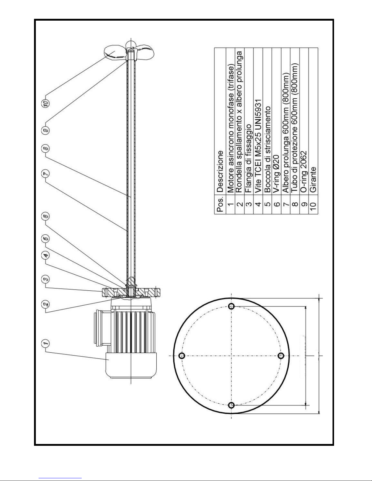
Ø140
Modello AF
N 4 fori Ø 6.5 su Ø120
Other manuals for AF
1
Table of contents
Other Etatron Mixer manuals


