ETC transtechnik E-Gate max User manual

E-Gate max
E-Gate max
User's Manual
Ethernet / DMX Matrix
Version 3.0.0
© 2011 Electronic Theatre Controls GmbH
All rights reserved.
No part of this manual may be reproduced
or copied in any form without the written
approval of Electronic Theatre Controls GmbH.
7241M1203-E

E-Gate max Contents
Table of contents:
Safety notes...............................................................................................................................1
Terms used................................................................................................................................1
Overview of functions...............................................................................................................2
E-Gate max DMX / Ethernet converter....................................................................................2
Network Protocols....................................................................................................................2
Miscellaneous..........................................................................................................................2
Functional description..............................................................................................................3
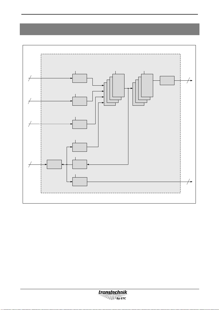
Block diagram............................................................................................................................4
Operation ...................................................................................................................................5
Menus.........................................................................................................................................9
Menus M01 through M11.......................................................................................................11
Menu M01 (Communication address)................................................................................11
Menu M02 (IP address)......................................................................................................11
Menu M03 (local/remote configuration)..............................................................................12
Menu M04 (DMX output display)........................................................................................12
Menu M05 (Ethernet output display)..................................................................................15
Menu M06 (System)...........................................................................................................16
Menu M07 (Timing)............................................................................................................18
Menu M08 (Patch)..............................................................................................................21
Menu M09 (Monitor)...........................................................................................................22
Menu M10 (Language).......................................................................................................23
Menu M11 (LCD contrast)..................................................................................................23
Technical Data.........................................................................................................................24
Appendix..................................................................................................................................26
Reset functions......................................................................................................................26
DMX timing parameters.........................................................................................................28
Table of figures:
Figure 1: E-Gate max block diagram...........................................................................................4
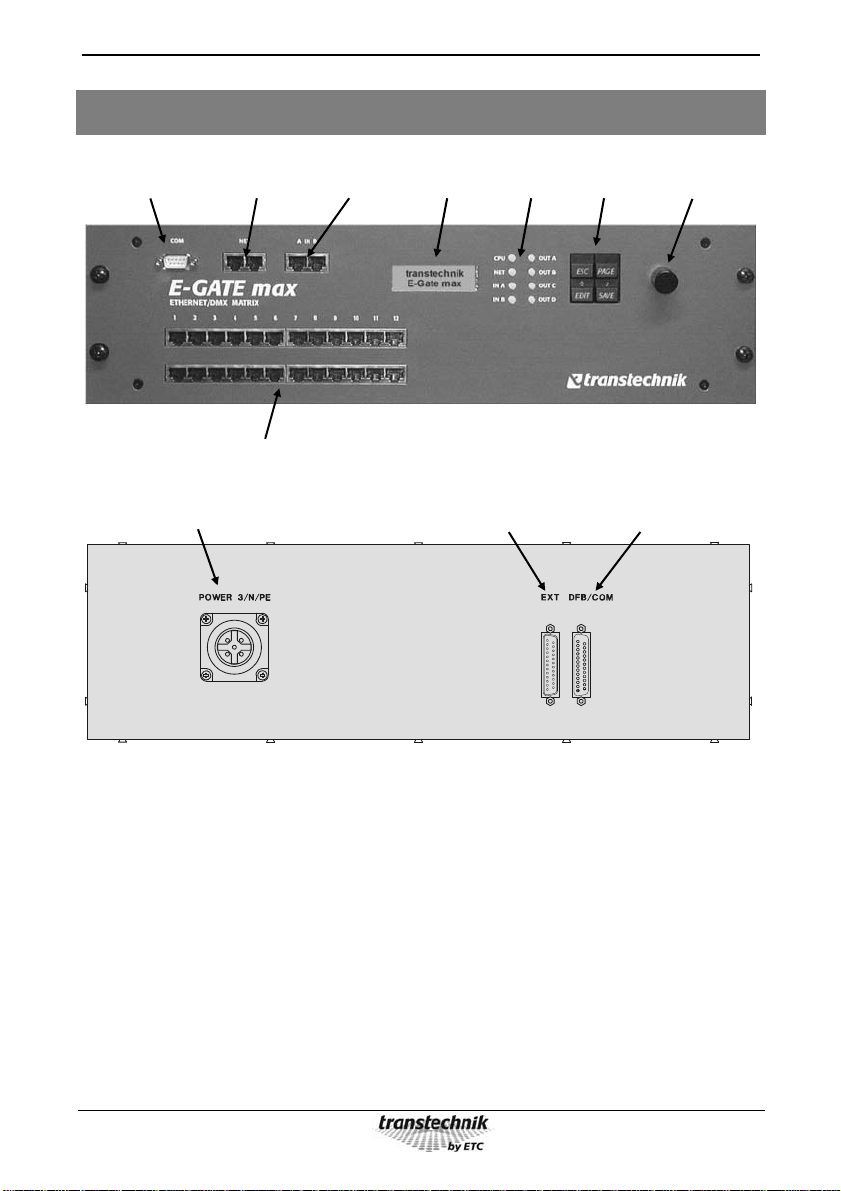
Figure 2: E-Gate max front panel................................................................................................5
Figure 3: E-Gate max rear panel.................................................................................................5

E-Gate max Safety notes, terms
1
Safety notes
Protective insulation and other protective measures in the E-Gate device ensure that you
cannot come into contact with any harmful electric currents.
Please observe the following in spite of this:
Never switch on equipment that is obviously damaged. Send the equipment to
transtechnik for repairs.
Equipment is only to be used for its intended purpose.
Avoid extreme mechanical loads (for example, throwing).
Do not allow the equipment to become wet.
If there is any reason to suspect a fault, unplug the equipment from the main
power supply immediately. Ensure that it cannot be started up again and send
the equipment to transtechnik for repairs.
Ensure that it is disconnected from the main power supply before opening.
Repair work may only be performed by an authorized dealer or transtechnik.
Terms used
Universe A universe is the Ethernet equivalent of a DMX line (512 DMX values).
E-Gatekeeper Operating software for central network-based management of all E-Gates of
type plus, pro and max

E-Gate max Overview of functions
2
Overview of functions
E-Gate max DMX / Ethernet converter
Increasingly, data communication in modern lighting systems is based on the Ethernet
standard. However, most older equipment and virtually all end devices continue to have
DMX512 interfaces. In order to allow such equipment to be incorporated seamlessly into an
Ethernet infrastructure and still be used in the same way as before, transtechnik has
designed the E-Gate to have following functions:
Supply of DMX data to the Ethernet
Supply of Ethernet data to DMX lines
Ethernet bridge between DMX devices
Protocol converter for heterogeneous networks
DMX merger and DMX filter
Network Protocols
E-Gates can process DMX data using the following network protocols:
Für das E-Gate können folgende Netzwerkprotokolle verwendet werden:
UDP Console family transtechnik NT/NTX, priority control
sACN Console family ETC Eos
IPX Console family AVAB Congo and some AVAB-consoles using network output
Most of the consoles can be configured to send all of these protocols. Within a installation one
common protocol can be used.
Miscellaneous
The configuration, i.e. the data that can be modified using control elements, is stored
permanently. Software updates can be installed via the RS-232 interface integrated into the
front panel or via the Ethernet.

E-Gate max Functional description
3
Functional description
E-Gate max is designed to be permanently installed in a rack and has the following features:
2 DMX inputs
4 DMX outputs
12 analog inputs
6 digital inputs
1 bidirectional Ethernet port
An interface for connecting conventional DMX90/FDX90 dimmer systems
The RS-232 interface (COM port) is located on the front panel for easy access
An integrated router to distribute output across the 12 DMX output lines
DMX inputs and outputs use RJ45 connectors are located on the front panel together with
other connections for easy patching
Redundant Ethernet connections can be realized via the integrated Ethernet switch on the
front.
E-Gate max can convert the data from up to five signal sources (DMX, Ethernet, Analog) into
DMX output values or filter criteria:
Ethernet DMX Conversion of Ethernet data from up to four lighting
consoles to DMX512, optionally using the HTP merge
function
Ethernet + DMX DMX Merging of the Ethernet data sent from two lighting
consoles with the two DMX512 inputs with the output
optionally sent to four DMX512 outputs
DMX DMX Reception of two DMX signals, optionally using the HTP
merge function, and output of the regenerated signals with
selectable DMX512 timing
DMX Ethernet Conversion of up to two DMX signals to Ethernet for
transmission to lighting consoles, dimmer systems or other
E-Gates
Ethernet Ethernet Converter and filter for Ethernet protocols
Analog DMX Conversion of 12 analog values to DMX512 with selectable
patching. Can also be used as a master fader.
Analog Ethernet Conversion of 12 analog values to Ethernet for use as a
master fader or as DMX input values

E-Gate max Block diagram
4
Block diagram
Parameter
Parameter
Parameter
Parameter
6
2
12
2
Parameter
2
Parameter
12
Input
DMX
Input
Analog
Input
Digital
Input
Ethernet
Merger
+
Filter
Output
DMX
RJ45
RJ45
25 pin
Sub-D
EXT
Parameter
Output
Ethernet
Parameter
FDX90
Feedback
25 pin
Sub-D
EXT
RJ45
25 pin
Sub-D
DFB
Patch
DMX
Ethernet
Switch
Figure 1: E-Gate max block diagram

E-Gate max Local operation
5
Operation
Figure 2: E-Gate max front panel
Figure 3: E-Gate max rear panel
The illuminated LCD display shows menus and messages.
2 x 12 x DMX outputs
RS-232 interface
(COM port)
230 VAC power connector RS485 interface
(dimmer feedback)
Input for analog
and digital signals
Rotary
adjustment knob
DMX inputs
A and B Display LEDs Input buttons
2 x Ethernet
Switch

E-Gate max Local operation
6
Eight LEDs display the operating status of the device:
CPU green device OK
red device is booting, overload network/CPU
orange start up
NET off no connection to network
green DMX input from network
blink: Egatekeeper & DMX input
green orange blink: Egatekeeper or
DMX input not configurated for the E-Gate
red no DMX from network
red blink more than four DMX sources
IN A/B off input unused
green receive DMX
red no DMX signal
OUT A/B/C/D off unused
green blink send DMX
red does not send DMX
red blink output in hold condition

E-Gate max Local operation
7
All operations are carried out using a menu system with an encoder (dial) and four buttons
according to the "SELECT - EDIT - SAVE – ESC" operating concept.
Allows you to scroll from one menu page to the next.
Prerequisite: Edit mode must be inactive. If edit mode is active, then
[Page] functions in the same way as [Esc] [Page].
Saves the current value and terminates edit mode.
Activates edit mode so that entries and changes can be made.
In edit mode you can change parameters (e.g. settings, the IP
address, etc.).
Some menus offer you the option of changing more than one
parameter. Repeatedly pressing [Edit] selects a different parameter
each time.
From some menu pages, this button will call the next menu level.
After selecting a parameter with the encoder, pressing [Edit] will select
this parameter for editing.
Terminates edit mode without saving any changes you have made.
Calls the menu level above the current level

E-Gate max Local operation
8
The LEDs on the [Edit] and [Save] buttons convey information about the current input status:
Edit mode is not active
Edit mode is active,
but no values have been
changed yet LED lit
Edit mode is active,
and at least one value has
been changed LED lit
LED lit
The encoder (dial) has two operating modes:
Edit mode is inactive The encoder (dial) is used to scroll through all the menus of the
current level one by one. When you get to the last menu, the
system automatically takes you back to the first menu (wrap
around).
Edit mode is active The encoder (dial) is used to modify the values of the marked
parameters. The wrap around feature also applies to many of
the parameters, once you reach the last value it automatically
goes back to the first.

E-Gate max Local operation
9
Menus
After switching on the device, the menu for the software
version and type of E-Gate appears. Input entered using
the dial and buttons is ignored during this time.
E-Gate max
Vers. 3.0.0
The standard display appears after 2 seconds.
transtechnik
E-Gate max
When a system name is assigned via the E-Gatekeeper,
the name is displayed (the system name cannot be edited
locally).
transtechnik
E-Gate ....
Status of input signals:
ETH = Status of the Ethernet line sent:
Input ETH: 1---
DMX: AB
Display: Meaning:
1 active
2 active
3 active
4 active
– inactive
x activated, but no input
DMX = Status of the 2 DMX inputs
Display: Meaning:
A A is active
B B is active
– inactive
x activated, but no input
The status displayed is identical to the status indicated by the 2 LEDs IN A and IN B on the
front panel of the device.

E-Gate max Local operation
10
Status of output signals:
Output ETH: --
DMX:!!!!!!!!!!!!
ETH = Status of the Ethernet output
Display: Meaning:
A A is active
B B is active
- inactive
! activated, but no output
DMX = Status of the 4 DMX outputs
Display: Meaning:
A A is active
B B is active
C C is active
D D is active
- inactive
! activated, but no output
The status displayed is identical to the status indicated by the 4 LEDs OUT A through OUT D
on the front panel of the device.

E-Gate max Local operation
11
Menus M01 through M11
Menu M01 (Communication address)
Set the communication address to be able to communicate
with the E-Gatekeeper software
COM M01
address: 1 A
Press [Edit]
and turn the encoder dial
Select the communication address:
Display: Meaning:
off No communication address or no
communication
1 Communication address 1 through 99
...
99
Press [Edit] again and turn the
encoder dial
Select the device:
Display: Meaning:
A Main device
B Backup device
If the communication address is specified, it must be unique.
Menu M02 (IP address)
Setting the IP address
IP address M02
192.009.200.000
Press [Edit] repeatedly and turn
the encoder dial Select the IP address:
Display: Meaning:
192.009.200.000 IP address
The IP address must be unique.
Exception: When the end address is 000, only reception is possible via Ethernet,
communication with the E-Gatekeeper not possible,
sending DMX Ethernet is not possible.

E-Gate max Local operation
12
Menu M03 (local/remote configuration)
Local / remote configuration
Local operation (cannot use edit function)
or
remote configuration (will only be activated by
E-Gatekeeper software), i.e. operation via the
E-GateKeeper software
(pressing [Edit] will return you to local operation, and all
settings that are not operated locally are lost)
Config. M03
local
Menu M04 (DMX output display)
The merge source(s) is(are) specified for each of the 12 DMX outputs with this menu. Merging
means that several input lines (Ethernet, DMX) are collected and output through one output
line. For each of the twelve logical output lines, up to two incoming Ethernet lines (universes 1
through 32) and the two DMX input lines are merged, i.e. they are grouped in any combination
according to the HTP principle.
DMX output display 1
DMX OUT 1 M04
DMX:AB ETH: 1 1
through through
DMX output display 12
DMX OUT 12 M04
DMX:AB ETH: 2 2
Turning the encoder dial Select the DMX output line
Display: Meaning:
DMX OUT 1 DMX output line 1
... through
DMX OUT 12 DMX output line 12

E-Gate max Local operation
13
Press [Edit]
and turn the encoder dial Select DMX input line A
Display: Meaning:
A enabled
– disabled
Press [Edit] again and turn the
encoder dial Select DMX input line B
Display: Meaning:
B enabled
– disabled
Press [Edit] again and turn the
encoder dial Select the first Ethernet input universe 1 through 32
Display: Meaning:
1...32 enabled
–– disabled
## not patched
Press [Edit] again and turn the
encoder dial Select the second Ethernet input universe 1 through 32
Display: Meaning:
1...32 enabled
– disabled
## not patched

E-Gate max Local operation
14
If both DMX input lines are disabled, then E-Gate max accepts the following input sources
twice:
Display: Meaning:
DMX: – – ETH: 1 2 Two sources are accepted for each universe 1 and 2
DMX: – – ETH: 1 1 Four sources are accepted for universe 1
DMX: – – ETH: 1 - Two sources are accepted for universe 1
If one or both DMX input lines are switched on, then E-Gate max accepts the following input
sources once only:
Display: Meaning:
DMX: A – ETH: 1 2
One source is accepted for each universe 1 and 2
DMX: – B ETH: 1 2
DMX: A B ETH: 1 2
DMX: A – ETH: 1 1
Two sources are accepted for universe 1
DMX: – B ETH: 1 1
DMX: A B ETH: 1 1
DMX: A – ETH: 1 -
Two sources are accepted for universe 1
DMX: – B ETH: 1 -
DMX: A B ETH: 1 -

E-Gate max Local operation
15
Menu M05 (Ethernet output display)
The sending of data via the Ethernet is set with this menu. Data can be sent via a maximum of
2 Ethernet lines.
Ethernet output 1 display
ETH OUT 1 M05
DMX A -> UNI 1
Ethernet output 2 display
ETH OUT 2 M05
DMX B -> UNI 32
Press [Edit]
and turn the encoder dial
Select the source:
Display: Meaning:
off No source (no data is sent via the
Ethernet line)
DMX A DMX input A
DMX B DMX input B
OUT A DMX output A
OUT B DMX output B
OUT C DMX output C
OUT D DMX output D
Press [Edit] again and turn the
encoder dial
Select the universes 1 through 32 to be sent:
Display: Meaning:
UNI 1 Universe 1
... through
UNI 32 Universe 32

E-Gate max Local operation
16
Menu M06 (System)
Menu for system settings
System M06
submenu [Edit]
Turning the encoder dial opens submenus S01 through S04:
Pressing [Edit] and turning the encoder dial opens
submenu S01 in which you can set the type of network
protocol for the Ethernet.
Mode IN/OUT S01
UDP&CAN -> UDP
Settings
UDP&ACN -> UDP
IPX -> IPX
UDP&IPX -> UDP UDP
UDP&ACN -> IPX
IPX -> UDP
Pressing [Edit] and turning the encoder dial opens
submenu S02 in which you can set the logical network to
integrate several venues or studios in a network, for
example.
Range of values: 0 to 9
Logical S02
network: 0
Pressing [Edit] and turning the encoder dial opens
submenu S03 in which you can set the IP network mask.
This mask can be used to set up more than 255 addresses
per network.
IP netmask S03
255.255.255.000
Pressing [Edit] and turning the encoder dial opens
submenu S04 in which you can set the address of the IP
gateway. This address is the address of the device that
allows access to another network.
IP gateway S04
192.009.200.254

E-Gate max Local operation
17
Pressing [Edit] and turning the encoder dial will reset the
various settings
(see also the Appendix: Reset functions)
Reset to ...
[Edit]
Reset to gate UDP DMX:
Universes 1 to 4 with the AVAB/UDP protocol are
converted to DMX OUT A to D.
DMX IN A/B are merged with DMX A or B. All other
functions are reset to their basic settings.
You cannot send via the Ethernet.
Reset to ...
UDP&ACN -> DMX
Reset to gate IPX DMX:
Universes 1 to 4 with the AVAB/IPX protocol are converted
to DMX OUT A to D.
DMX IN A/B are merged with DMX A or B. All other
functions are reset to their basic settings.
You cannot send via the Ethernet.
Reset to ...
IPX -> DMX
Reset to gate DMX UDP:
DMX IN A and B are sent as universe 1 and 2 with the
AVAB/UDP protocol and output to DMX A or B.
Reset to ...
DMX -> UDP
Reset to gate DMX IPX:
DMX IN A and B are sent as universe 1 and 2 with the
AVAB/IPX protocol and output to DMX A or B.
Reset to ...
DMX -> IPX
Reset to merge DMX DMX:
DMX IN A and B are merged, i.e. combined and output
identically to DMX A to D.
You cannot send or receive via the Ethernet.
Reset to ...
Merge DMX -> DMX
Reset to factory settings
Reset to ...
factory settings

E-Gate max Local operation
18
Menu M07 (Timing)
Menu for the timing settings
Timing M07
submenu [Edit]
Turning the encoder dial opens submenus T01 through T04:
Pressing [Edit] and turning the encoder dial opens
submenu T01 in which you can set the general response
of the Ethernet-Output when the input signal is dropped.
Inputfail T01
ETH OUT : off
Press [Edit]
and turn the encoder dial
Select the output line:
Display: Meaning:
ETH OUT Both Ethernet outputs
DMX OUT A DMX output A
DMX OUT B DMX output B
DMX OUT C DMX output C
DMX OUT D DMX output D
Press [Edit] again and turn the
encoder dial
Select the timeout period:
Display: Meaning:
off Disabled
hold Buffer the signal instead of switching
it off
Table of contents
Other ETC Network Router manuals