4
Chapter 2 Hardware Installation
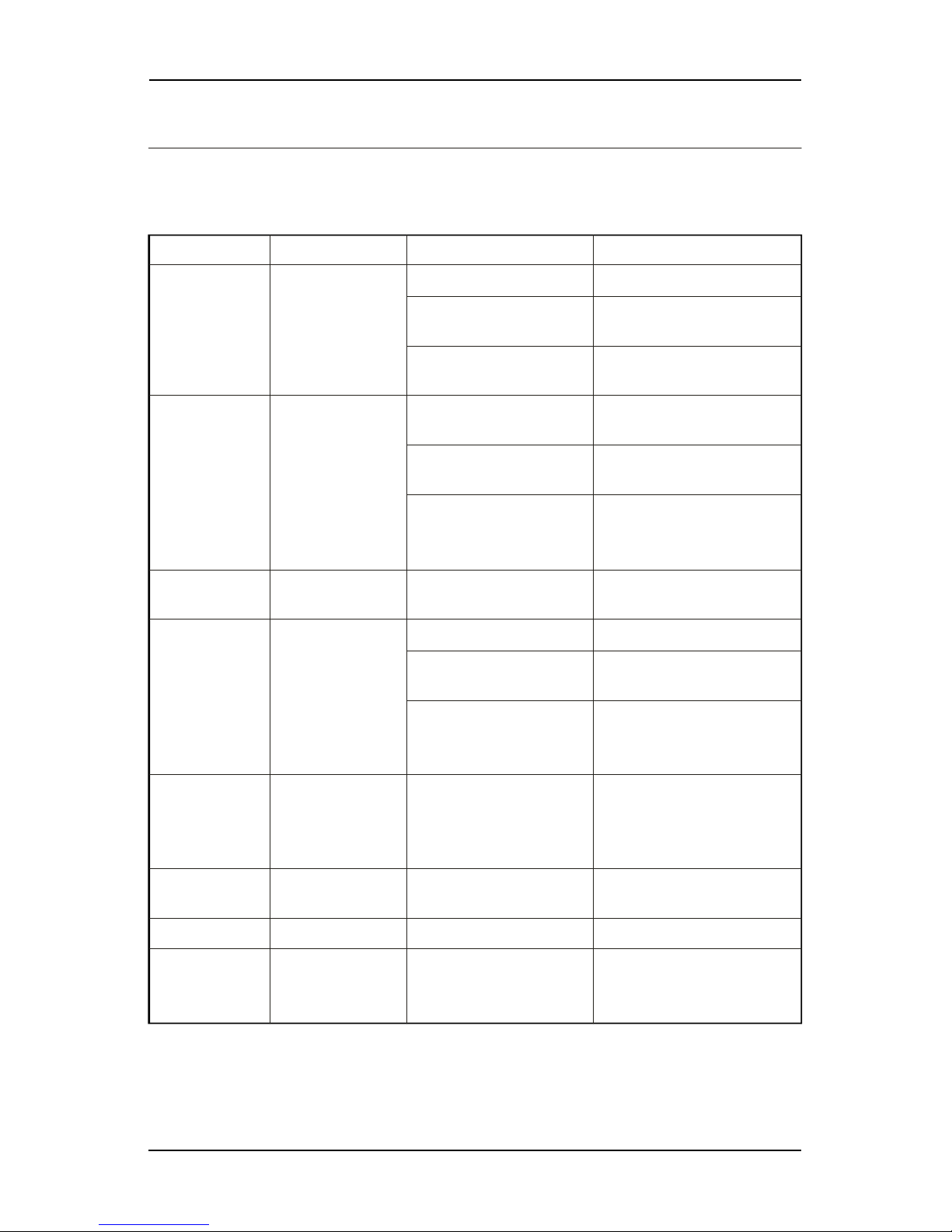
2.3 LEDs Indicators
LED Status
On
OFF
LED light activity Modem status
LED ON Permanent Modem is switched on
Not registered on the network
LED Flashing Slowly
LED Flashing Rapidly
LED OFF
Idle mode Connec ted to the network
Transmission mod e
Modem is switche d off.
2.4 Hardware Installation
2.41 MODEM QuickStart
To set up the modem, do the following:
Press SIM card holder ejector (yellow button) with a sharp object (the tip of a
pen for example).
Insert the SIM card in the holder.
Verify the SIM card fits in the holder properly.
Connect the antenna to the SMA connector.
Connect both sides of the serial and control cable
Connect the power adaptor to the power supply, and plug into the Modem.
Now the modem is ready to work. Refer to Chapter 3 for some AT commands
to configure the modem.
2.42 Checking the communication with the modem
Connect the RS232 link between the DTE (port COM) and the modem(DCE).
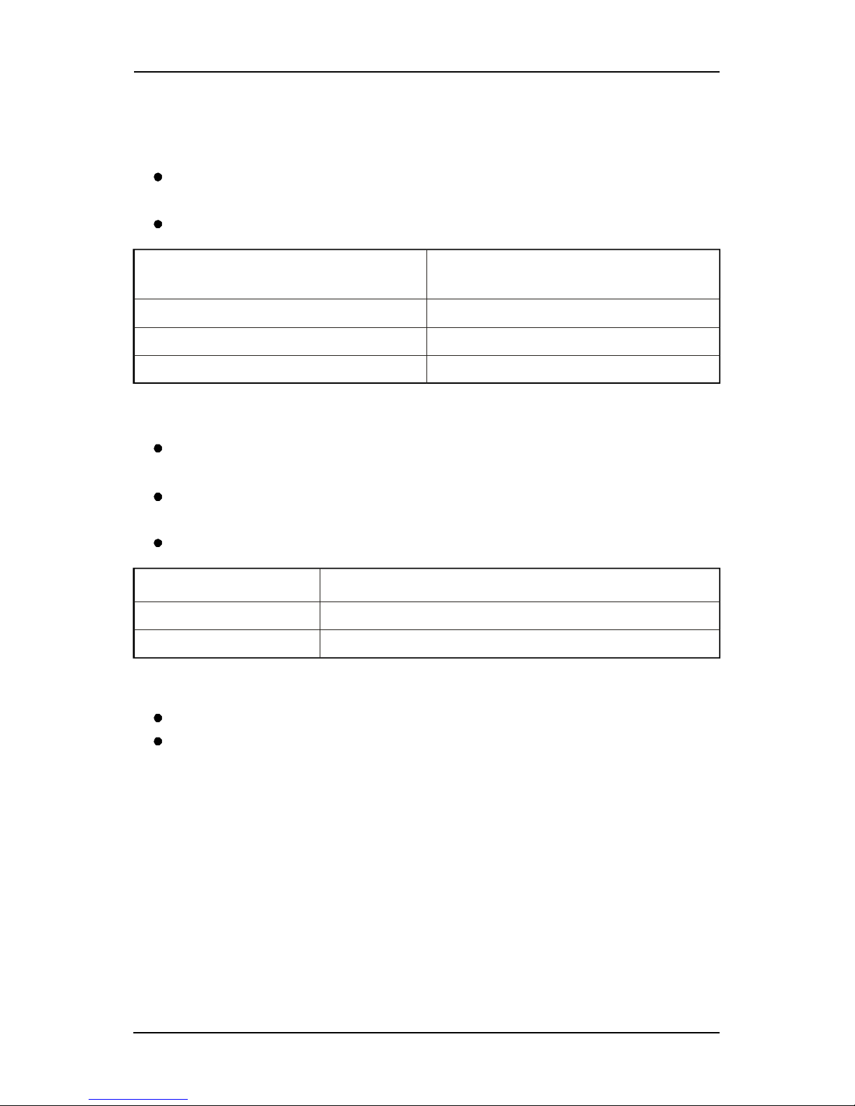
Configure the RS232 port of the DTE as follows:
Bits per second: 115200 bps or 9600 bps
Data bits: 8
Parity: None None
Stop bits: 1
Flow control: Hardware Flow control control.
Using a communication software such as Hyperterminal program, enter the
AT command. The response of the modem must be OK displayed in the
Hyperterminal window.
If the communication cannot be established with the modem, do the following:
Check the RS232 connection between the DTE and the modem (DCE),
Check the configuration of the port COM used on the DTE.
GSM/GPRS Modem User's Manual