ELPRO 905U-E User manual

ELPRO Technologies Pty Ltd, 9/12 Billabong Street, Stafford Q 4053, Australia.
Web: www.elprotech.com
User Manual
905U-E Wireless Ethernet
DRAFT

905U-E Wireless Ethernet User Manual
Man_905U-E Rev 1.0 Draft Page 2
Thank you for your selection of the 905U-E Wireless Ethernet Modem. We trust it will
give you many years of valuable service.
ATTENTION!
Incorrect termination of supply wires may
cause internal damage and will void warranty.
To ensure your 905U-E enjoys a long life,
double check ALL your connections with
the user’s manual
before turning the power on.
Caution!
For continued protection against risk of fire, replace the internal module fuse only with the same type and
rating.
CAUTION:
To comply with FCC RF Exposure requirements in section 1.1310 of the FCC Rules, antennas used with
this device must be installed to provide a separation distance of at least 20 cm from all persons to satisfy RF
exposure compliance.
DO NOT:
operate the transmitter when someone is within 20 cm of the antenna
operate the transmitter unless all RF connectors are secure and any open connectors are properly
terminated.
operate the equipment near electrical blasting caps or in an explosive atmosphere
All equipment must be properly grounded for safe operations. All equipment should be serviced only by a
qualified technician.

Important Notices
Page 3©June 2005
FCC Notice:
This user’s manual is for the ELPRO 905U-D radio telemetry module. This device complies with Part
15.247 of the FCC Rules.
Operation is subject to the following two conditions:
qThis device may not cause harmful interference and
qThis device must accept any interference received, including interference that may cause undesired
operation.
This device must be operated as supplied by ELPRO Technologies. Any changes or modifications made to
the device without the written consent of ELPRO Technologies may void the user’s authority to operate the
device.
End user products that have this device embedded must be supplied with non-standard antenna connectors,
and antennas available from vendors specified by ELPRO Technologies. Please contact ELPRO
Technologies for end user antenna and connector recommendations.
Notices: Safety
Exposure to RF energy is an important safety consideration. The FCC has adopted a safety standard for
human exposure to radio frequency electromagnetic energy emitted by FCC regulated equipment as a result
of its actions in Docket 93-62 and OET Bulletin 65 Edition 97-01.
Limited Warranty, Disclaimer and Limitation of Remedies
ELPRO products are warranted to be free from manufacturing defects for a period of 24 months from the
effective date of purchase by the end user. The effective date of purchase is decided solely by ELPRO
Technologies.
This warranty does not extend to:
-failures caused by the operation of the equipment outside the particular product's specification, or
-use of the module not in accordance with this User Manual, or
-abuse, misuse, neglect or damage by external causes, or
-repairs, alterations, or modifications undertaken other than by an authorized Service Agent.
ELPRO’s liability under this warranty is limited to the replacement or repair of the product. This warranty is
in lieu of and exclusive of all other warranties. This warranty does not indemnify the purchaser of products
for any consequential claim for damages or loss of operations or profits and ELPRO is not liable for any
consequential damages or loss of operations or profits resulting from the use of these products. ELPRO is
not liable for damages, losses, costs, injury or harm incurred as a consequence of any representations,
warranties or conditions made by ELPRO or its representatives or by any other party, except as expressed
solely in this document.

905U-E Wireless Ethernet User Manual
Man_905U-E Rev 1.0 Draft Page 4

Important Notices
Page 5©June 2005
Important Notice
ELPRO products are designed to be used in industrial environments, by experienced industrial engineering
personnel with adequate knowledge of safety design considerations.
ELPRO radio products are used on unprotected license-free radio bands with radio noise and interference.
The products are designed to operate in the presence of noise and interference, however in an extreme case,
radio noise and interference could cause product operation delays or operation failure. Like all industrial
electronic products, ELPRO products can fail in a variety of modes due to misuse, age, or malfunction. We
recommend that users and designers design systems using design techniques intended to prevent personal
injury or damage during product operation, and provide failure tolerant systems to prevent personal injury or
damage in the event of product failure. Designers must warn users of the equipment or systems if adequate
protection against failure has not been included in the system design. Designers must include this Important
Notice in operating procedures and system manuals.
These products should not be used in non-industrial applications, or life-support systems, without consulting
ELPRO Technologies first.
1. A radio license is not required in some countries, provided the module is installed using the aerial and
equipment configuration described in the 905U-EInstallation Guide. Check with your local
distributor for further information on regulations.
2. Operation is authorized by the radio frequency regulatory authority in your country on a non-
protection basis. Although all care is taken in the design of these units, there is no responsibility
taken for sources of external interference. Systems should be designed to be tolerant of these
operational delays.
3. To avoid the risk of electrocution, the aerial, aerial cable, serial cables and all terminals of the 905U-
D module should be electrically protected. To provide maximum surge and lightning protection, the
module should be connected to a suitable earth and the aerial, aerial cable, serial cables and the
module should be installed as recommended in the Installation Guide.
4. To avoid accidents during maintenance or adjustment of remotely controlled equipment, all
equipment should be first disconnected from the 905U-E module during these adjustments.
Equipment should carry clear markings to indicate remote or automatic operation. E.g. "This
equipment is remotely controlled and may start without warning. Isolate at the switchboard before
attempting adjustments."
5. The 905U-E module is not suitable for use in explosive environments without additional protection.

905U-E Wireless Ethernet User Manual
Man_905U-E Rev 1.0 Draft Page 6
CONTENTS
CHAPTER ONE INTRODUCTION ...............................................................................87
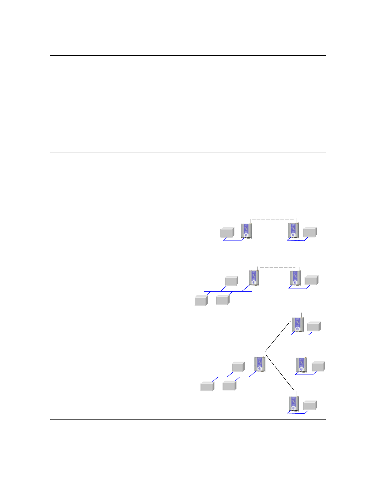
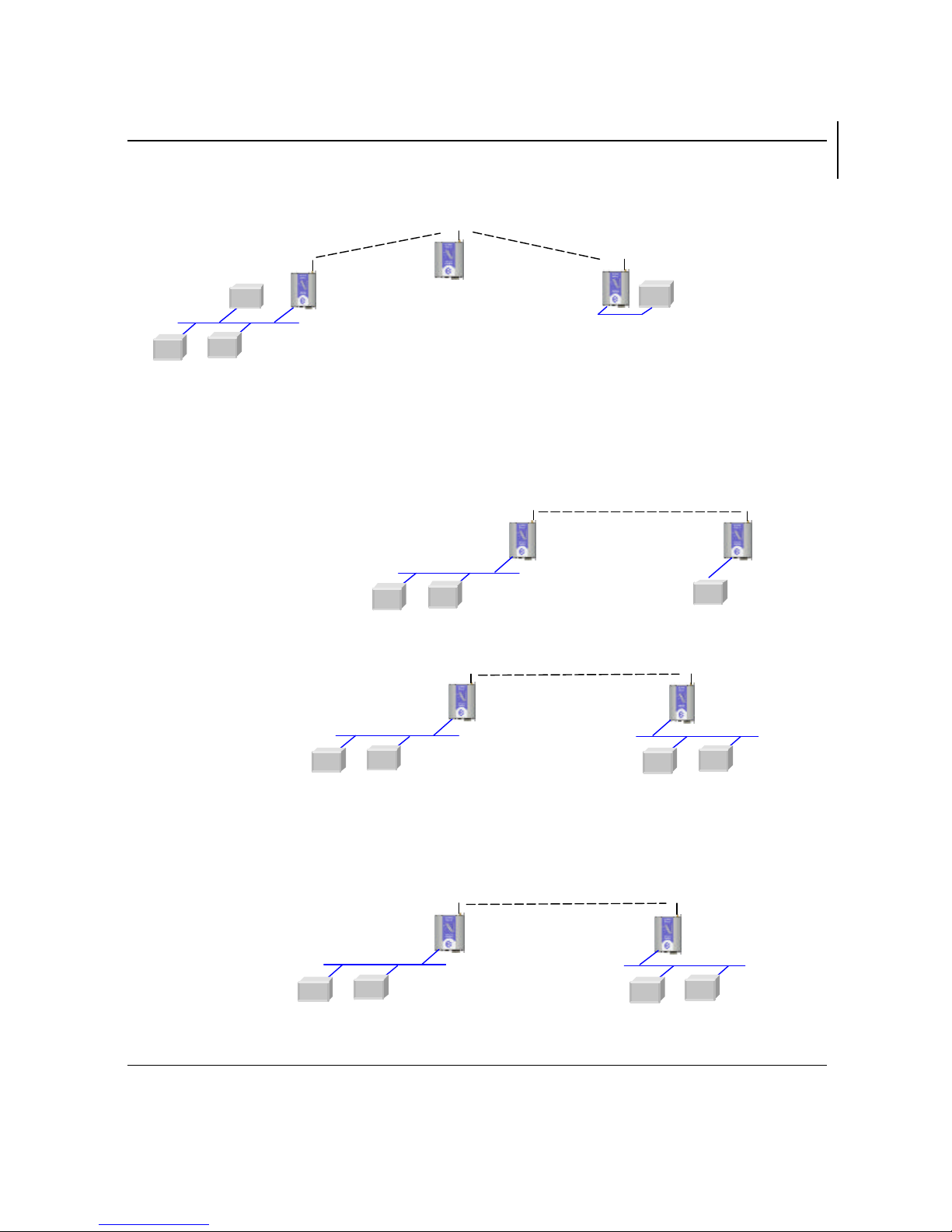
1.1 NETWORK TOPOLOGY....................................................................................................87
1.2 GETTING STARTED QUICKLY .......................................................................................109
CHAPTER TWO INSTALLATION................................................................................1110
2.1 GENERAL...................................................................................................................1110
2.2 ANTENNA INSTALLATION..........................................................................................1110
2.2.1 Dipole and Collinear antennas.............................................................................1312
2.2.2 Yagi antennas.....................................................................................................1413
2.3 POWER SUPPLY..........................................................................................................1514
2.4 SERIAL CONNECTIONS...............................................................................................1514
2.4.1 RS232 Serial Port..............................................................................................1514
2.4.2 RS485 Serial Port..............................................................................................1615
CHAPTER THREE OPERATION..............................................................................1817
3.1 START-UP .................................................................................................................1817
3.2 DEFAULT CONFIGURATION........................................................................................1918
3.3 CONFIGURING THE UNIT FOR THE FIRST TIME.............................................................2019
3.4 CONFIGURING ADDRESSES .........................................................................................2524
3.5 ETHERNET DATA.......................................................................................................2726
3.6 NORMAL OPERATION................................................................................................2726
3.7 SPREAD-SPECTRUM OPERATION...............................................................................2827
3.8 RADIO CONFIGURATION MENU..................................................................................2827
3.9 SPANNING TREEALGORITHM / REDUNDANCY ............................................................3029
3.10 WIRELESS MESSAGE FILTERING..................................................................................3130
3.11 SERIAL PORT CONFIGURATION..................................................................................3331
3.12 MODULE INFORMATION CONFIGURATION..................................................................3332
3.13 REMOTE CONFIGURATION .........................................................................................3332
3.14 CONFIGURATION EXAMPLES......................................................................................3433
CHAPTER FOUR DIAGNOSTICS .................................................................................4038
4.1 DIAGNOSTICS CHART................................................................................................4038
4.2 DIAGNOSTIC INFORMATIONAVAILABLE....................................................................4038
4.2.1 Connectivity.......................................................................................................4038
4.2.2 Monitor Communications ...................................................................................4038

Contents
Page 7©June 2005
4.2.3 Statistics............................................................................................................4139
4.2.4 Network Traffic Analysis....................................................................................4139
4.3 TESTING RADIO PATHS..............................................................................................4139
4.4 UTILITIES...................................................................................................................4139
4.4.1 PING................................................................................................................4139
4.4.2 IPCONFIG.......................................................................................................4240
4.4.3 ARP ..................................................................................................................4341
4.4.4 ROUTE.............................................................................................................4341
CHAPTER FIVE SPECIFICATIONS..............................................................................4643
APPENDIX A FIRMWARE UPGRADE.........................................................................4744
APPENDIX B GLOSSARY...............................................................................................4946

905U-E Wireless Ethernet User Manual
Man_905U-E Rev 1.0 Draft Page 8
Chapter One INTRODUCTION
The 905U-E Wireless Ethernet module provides wireless connections between Ethernet devices or Ethernet
wired networks (LAN’s). It has an internal 900MHz spread spectrum frequency hopping wireless
transceiver, which can be used without a radio license in many countries.
The 905U-E has a standard RJ45 Ethernet connection which will operate at up to 100Mbit/sec. The module
will transmit the Ethernet messages on the wireless band at up to 200 Kbit/sec.
1.1 Network Topology
The 905U-E is an Ethernet device, and must be configured as part of an Ethernet network. Each 905U-E
must be configured as:
qan “Access Point” or a “Client”, and
qa “Bridge” or a “Router”.
Access Point vs Client
The Access Point unit acts as the “wireless master” unit. The
Access Point sets up the wireless links to the Client units,
and controls the wireless communications. The following
diagram shows two Ethernet devices being linked. One
905U-E is configured as an Access Point and one as a Client
-in this example it doesn’t mater which unit is the Access
Point.
The next diagram shows an existing LAN being
extended using 905U-E’s. In this example, the
Access Point should be configured at the LAN end
-although the wireless link will still work if the Client
is at the LANend.
An Access Point can connect to multiple Clients. In this
case, the Access Point should be the “central” unit.
Client
Ethernet
Device
Access
Point
LAN
Ethernet Device
Client
Access
Point
LAN
Ethernet Device
Client
Access
Point
Client
Client

Chapter One Introduction
Page 9©June 2005
LAN A
Client
Bridge
Access Point
Router
192.168.0.34
169.254.102.54
LAN B
169.254.102.17
169.254.102.53
An Access Point could be used as a “Repeater” unit to connect two 905U-E Clients which do not have
direct reliable radio paths.
Bridge vs Router
Each 905U-E is configured with an IP address for the Ethernet side, and another for the wireless side.
A Bridge connects devices within the same Ethernet network -for example, extending an existing Ethernet
LAN. For a Bridge, the IP
address for the wireless side is the
same as the Ethernet side.
A Router connects devices on
different LAN’s. The
IP addresses for the
Ethernet and wireless
sides are different.
In the above example, the wireless link is part of LAN A, with the Client unit acting as a Router between
LAN A and LAN B. Alternately, the Access Point could be configured as a Router -the wireless link is
then part of LAN B.
LAN
Ethernet device
Client
Access
Point
Client
LAN
Client
Bridge
Access Point
Bridge
192.168.0.34
192.168.0.34 192.168.0.72
192.168.0.72
LAN A
Client
Router
Access Point
Bridge
192.168.0.
34
192.168.0.34
LAN B
169.254.102.17
192.168.0.72

905U-E Wireless Ethernet User Manual
Man_905U-E Rev 1.0 Draft Page 10
There is limit of two Routers within the same radio network. There is no limit to the number of Bridges in the
same network -although there is a limit of 255 Client units linked to any one Access Point.
1.2 Getting Started Quickly
Most applications for the 905U-E require little configuration. The 905U-E has many sophisticated features,
however if you don’t require these features, this section will allow you to configure the units quickly.
First, read Section 2, “Installation”. The 905U-E requires an antenna and a power supply.
qPower the 905U-E and make an Ethernet connection to your PC (for further information on how to do
this, refer to section 3.3)
qSet the 905U-E address settings as per section 3.4 -also select Access Point / Client and Bridge /
Router
qSave the configuration -the 905U-E is now ready to use.
Before installing the 905U-E, bench test the system. It is a lot easier to locate problems when the equipment
is all together.
There are other configuration setting which may or may not improve the operation of the system. For detail
on these settings, refer to section 3.
Client
Router
LAN C
169.254.102.17
192.168.0.73
LAN A
Client
Bridge
Access Point
Bridge
192.168.0.34
192.168.0.34 192.168.0.72
192.168.0.72
Client
Router
LAN B
169.254.109.40
192.168.0.74

Chapter Two Installation
Page 11 ©June 2005
Chapter Two INSTALLATION
2.1 General
The 905U-E module is housed in an rugged aluminum case, suitable for DIN-rail mounting. Terminals
will accept wires up to 12 gauge (2.5 sqmm) in size.
All connections to the module must be SELV. Normal 110-240V mains supply should not be
connected to any terminal of the 905U-E module. Refer to Section 2.3 Power Supply.
Before installing a new system, it is preferable to bench test the complete system. Configuration
problems are easier to recognize when the system units are adjacent. Following installation, the most
common problem is poor communications caused by incorrectly installed antennas, or radio interference
on the same channel, or the radio path being inadequate. If the radio path is a problem (ie path too
long, or obstructions in the way), then higher performance antennas or a higher mounting point for the
antenna may rectify the problem. Alternately, use an intermediate 905U-E Module as a repeater.
The foldout sheet 905U-EInstallation Guide provides an installation drawing appropriate to most
applications. Further information is detailed below.
Each 905U-E module should be effectively earthed via the "GND" terminal on the 905U-E module -
this is to ensure that the surge protection circuits inside the 905U-E module are effective.
2.2 Antenna Installation
The 905U-E module will operate reliably over large distances. The distance which may be reliably
achieved will vary with each application -depending on the transmit power (user configurable), type
and location of antennas, the degree of radio interference, and obstructions (such as hills or trees) to the
radio path. Typical reliable distances for 1W transmit power are :
USA/Canada 15 miles 6dB net gain antenna configuration permitted (4W ERP)
Australia/NZ 12 km unity gain antenna configuration (1W ERP)
Longer distances can be achieved if one antenna is mounted on top of a hill.
To achieve the maximum transmission distance, the antennas should be raised above intermediate
obstructions so the radio path is true “line of sight”. Because of the curvature of the earth, the antennas
will need to be elevated at least 15 feet (5 metres) above ground for paths greater than 3 miles (5 km).
The modules will operate reliably with some obstruction of the radio path, although the reliable distance
will be reduced. Obstructions which are close to either antenna will have more of a blocking affect than
obstructions in the middle of the radio path. For example, a group of trees around the antenna isa
larger obstruction than a group of trees further away from the antenna. The 905U-E modules provide a
diagnostic feature which displays the radio signal strength of transmissions.
Line-of-sight paths are only necessary to obtain the maximum range. Obstructions will reduce the
range, however may not prevent a reliable path. A larger amount of obstruction can be tolerated for

905U-E Wireless Ethernet User Manual
Man_905U-E Rev 1.0 Draft Page 12
shorter distances. For very short distances, it is possible to mount the antennas inside buildings. An
obstructed path requires testing to determine if the path will be reliable -refer the section 6 of this
manual.
In certain circumstances, much longer distances can be achieved by reducing the transmitter power and
using higher gain antennas. Although the effective radiated power at the transmitter end is the same, the
additional antenna gain at the receiver gives increased distance. This is only true for locations of low
background noise as the antenna gain will also increase the noise level. For example, in America where
4W ERP power is permitted, a combination of 0.1W transmitter power and 16dB antenna gain (giving
4W ERP) can give distances of more than 60 miles (100km). However antennas will need to be
elevated to give line-of-sight. This is a special installation and advice from ELPRO should be sought.
Where it is not possible to achieve reliable communications between two 905U modules, then a third
905U module may be used to receive the message and re-transmit it. This module is referred to as a
repeater. This module may also have a host device connected to it.
An antenna should be connected to the module via 50 ohm coaxial cable (eg RG58, RG213 or Cellfoil)
terminated with a male SMA coaxial connector. The higher the antenna is mounted, the greater the
transmission range will be, however as the length of coaxial cable increases so do cable losses. For use
on unlicensed frequency channels, there are several types of antennas suitable for use. It is important
antenna are chosen carefully to avoid contravening the maximum power limit on the unlicensed channel
-if in doubt refer to an authorized service provider.
The net gain of an antenna/cable configuration is the gain of the antenna (in dBi) less the loss in the
coaxial cable (in dB).
The maximum net gain of the antenna/cable configuration permitted is
Country Max. gain (dB)
USA / Canada 6
Australia / New Zealand 0 for 1W transmit power
10 for 0.1W transmit power
The gains and losses of typical antennas are
Antenna Gain (dB) Antenna Gain (dB)
Dipole with integral 15’ cable 06 element Yagi 10
5dBi Collinear (3dBd) 59 element Yagi 12
8dBi Collinear (6dBd) 816 element Yagi 15
Cable type Length (m) Loss (dB)
CC10/900 10 3
CC20/900 20 6

Chapter Two Installation
Page 13 ©June 2005
The net gain of the antenna/cable configuration is determined by adding the antenna gain and the cable
loss. For example, a 6 element Yagi with 70 feet (20 metres) of Cellfoil has a net gain of 4dB (10dB
–6dB).
Connections between the antenna and coaxial cable should be carefully taped to prevent ingress of
moisture. Moisture ingress in the coaxial cable is a common cause for problems with radio systems, as
it greatly increases the radio losses. We recommend that the connection be taped, firstly with a layer of
PVC Tape, then with a vulcanizing tape such as “3M 23 tape”, and finally with another layer of PVC
UV Stabilized insulating tape. The first layer of tape allows the joint to be easily inspected when trouble
shooting as the vulcanizing seal can be easily removed.
Where antennas are mounted on elevated masts, the masts should be effectively earthed to avoid
lightning surges. For high lightning risk areas, surge suppression devices between the module and the
antenna are recommended. If the antenna is not already shielded from lightning strike by an adjacent
earthed structure, a lightning rod may be installed above the antenna to provide shielding.
2.2.1 Dipole and Collinear antennas.
A collinear antenna transmits the same amount of radio power in all directions -as such that are easy
to install and use. The dipole antenna with integral 15 ‘ cable does not require any additional coaxial
cable, however a cable must be used with the collinear antennas.
Collinear and dipole antennas should be mounted vertically, preferably 3 feet (1 metre) away from a
wall or mast to obtain maximum range.
1m minimum
COLINEAR
ANTENNA
MAST
EARTH STAKE
IF GROUND CONDITIONS ARE
POOR, INSTALL MORE THAN
ONE STAKE
INSTALL AERIAL ABOVE
LOCAL OBSTRUCTIONS
ANT
905U
SURGE
ARRESTOR
(OPTIONAL) COAXIAL CABLE
WEATHERPROOF
CONNECTORS WITH
“3M 23” TAPE
STRESS RELIEF LOOP
PROVIDE GOOD
GROUND
CONNECTION TO
MAST, MODULE
AND SURGE
ARRESTOR
GND

905U-E Wireless Ethernet User Manual
Man_905U-E Rev 1.0 Draft Page 14
2.2.2 Yagi antennas.
A Yagi antenna provides high gain in the forward direction, but lower gain in other directions. This
may be used to compensate for coaxial cable loss for installations with marginal radio path.
The Yagi gain also acts on the receiver, so adding Yagi antennas at both ends of a link provides a
double improvement.
Yagi antennas are directional. That is, they have positive gain to the front of the antenna, but negative
gain in other directions. Hence Yagi antennas should be installed with the central beam horizontal and
must be pointed exactly in the direction of transmission to benefit from the gain of the antenna. The Yagi
antennas may be installed with the elements in a vertical plane (vertically polarized) or in a horizontal
plane (horizontally polarized). For a two station installation, with both modules using Yagi antennas,
horizontal polarization is recommended. If there are more than two stations transmitting to a common
station, then the Yagi antennas should have vertical polarization, and the common (or “central” station
should have a collinear (non-directional) antenna.
Also note that Yagi antennas normally have a drain hole on the folded element -the drain hole should
be located on the bottom of the installed antenna.
905U
Antenna installed
with drain holes
down
Coax feed looped
at connection
90
o

Chapter Two Installation
Page 15 ©June 2005
2.3 Power Supply
The 905U-E module can be powered from a 10 -30VDC power supply. The power supply should be
rated at 1 Amp and be CSA Certified Class 2. The negative side of the supply should be connected to a
good “ground” point for surge protection. The supply negative is connected to the unit case internally.
The positive side of the supply must
not be connected to earth. The DC
supply may be a floating supply or
negatively grounded. The power
requirements of the 905U-E unit is
280mA @ 12V or 150mA @ 24VDC.
This is inclusive of radio and Ethernet
ports active, & serial port plugged in.
Transmission current (1W RF) is
nominally 500mA at 12V, 250mA at 24VDC.
2.4 Serial Connections
2.4.1 RS232 Serial Port
The serial port is a 9 pin DB9 female and provides for connection to a host device as well as a PC
terminal for configuration, field testing and for factory testing. This port is internally shared with the
RS485 -ensure that the RS485 is disconnected before attempting to use the RS232 port.
Communication is via standard RS232 signals. The 905U-E is configured as DCE equipment with the
pinouts detailed below.
905U
-
E
DB9
MALE
DTE HOST
DB9
FEMALE
905U
-
E
DB9
MALE
DCE HOST
DB9
MALE
Hardware handshaking using the CTS/RTS lines is provided. The CTS/RTS lines may be used to reflect
the status of the local unit’s input buffer, or may be configured to reflect the status of CTS/RTS lines at
the remote site. The 905U-E does not support XON/XOFF.
Example cable drawings for connection to a DTE host (a PC) or another DCE hosts (or modem) are
detailed above.
+
_
A
B
-
+
COM
DIO
905U-E
10
-
30
VDC
RS485
SUPPLY

905U-E Wireless Ethernet User Manual
Man_905U-E Rev 1.0 Draft Page 16
DB9 Connector Pinouts
Pin Name Direction Function
1DCD Out Data carrier detect–
-on when link is established in controlled mode
-on always in transparent mode
2RD Out Transmit Data–Serial Data Output
3TD In Receive Data –Serial Data Input
4DTR In Data Terminal Ready -DTR can be configured to initiate low power
mode, or to force a link disconnection (“hang up” in controlled mode.
5SG Signal Ground
6DSR Out Data Set Ready -always high when unit is powered on.
7RTS In Request to Send -hardware flow control configurable
8CTS Out Clear to send -hardware flow control configurable
9RI Ring indicator -indicates another module is attempting to connect in
controlled mode.
2.4.2 RS485 Serial Port
The RS485 port provides for communication between the 905U-E unit and its host device using a multi-
drop cable. Up to 32 devices may be connected in each multi-drop network. Note that the RS485
port is shared internally with the RS232 port -make sure that the RS232 port is disconnected before
using the RS485 port.
As the RS485 communication medium is shared, only one of the units on the RS485 cable may send
data at any one time. Thus communication protocols based on the RS-485 standard require some type
of arbitration.
RS485 is a balanced, differential standard but it is recommended that shielded, twisted pair cable be
used to interconnect modules to reduce potential RFI. It is important to maintain the polarity of the two
RS485 wires. An RS485 network should be wired as indicated in the diagram below and terminated at
each end of the network with a 120 ohm resistor. On-board 120 ohm resistors are provided and may
be engaged by operating the single DIP switch in the end plate next to the RS485 terminals. The DIP
switch should be in the “1” or “on” position to connect the resistor. If the module is not at one end of the
RS485 cable, the switch should be off.

Chapter Two Installation
Page 17 ©June 2005
HOST 905U-EHOST
RS485 CONNECTIONS
120
Ω
RS485
SUPPLY
RS232
DIP SWITCH
FOR 120
Ω
120
Ω
HOST HOST
905U-E
+
-
+
-
+
-
RS485 CONNECTION USING TERMINATING RESISTOR
ETHERNET
DIO
DEFAULTS DIP SWITCH

905U-E Wireless Ethernet User Manual
Man_905U-E Rev 1.0 Draft Page 18
Chapter Three OPERATION
3.1 Start-up
“Access Point” Start-up
An Access Point unit starts and immediately begins transmitting periodic messages called beacons.
These beacon messages are messages contain information for Clients on how to establish a link with the
Access Point.
Any Client that hears the messages, which are not already linked to another Access Point unit, will
respond and links will be established between the new Access Point and these Clients.
“Client” Start-up
When a Client powers up, it immediately scans for messages from Access Point units. The Client will
continue to scan for twice the configured beacon interval in the Client. During the scan, the RX led will
flicker now and again indicating messages received, perhaps from an Access Point. If the Client finds
suitable Access Points during the scan, it will then attempt to establish a link with the Access Point with
the strongest radio signal.
Link Establishment
When the Client wishes to establish a link with an Access Point it follows a two step process. The first
step is “authentication”. During this step the Client and Access Point check if they can establish a secure
link, based upon the configured security encryption.
Once the Client has been authenticated, it will then request a link. This step is called “association”.
While no links have been established, the LINK led will be OFF. Once a single link has been
established, the LINK led is ON.
After the link is established, data may be transferred in both directions. The Access Point will act as a
master-unit and will control the flow of information to the Clients linked to it.
The maximum number of 255 Clients may be linked to an Access Point.
How a Link connection is lost
The 905U-E will reset the Link if:
•Excessive retries: When a 905u-E unit transmit a wireless message to another unit, the destination
unit will transmit back an acknowledgment. If the source unit does not receive an acknowledgment,
it will re-send the message -this is known as a “re-try”. Both Access Point and Client will drop the
link if the number of retries for a single packet exceeds (7) times. Packets are retransmitted
according to an increasing time delay between retries, with each attempt on a different frequency.
•Inactivity: During periods of inactivity, Clients will periodically check that the link to the Access
Point remains intact. This process is called “reassociation”, and will occur approximately (6) beacon
intervals after the last packet was sent to the Access Point. If a Client unit does not get a response

Chapter Three Operation
Page 19 ©June 2005
from its Access Point, it will retry the reassociation request (7) times before resetting the link. If
an Access Point does not receive any traffic from a Client, including reassociation requests, within
(12) beacon intervals, the Access Point will reset the link.
After a Client has reset it’s Link status, it will start scanning for an Access Point, as if it has just started
up.
LED Indication
The following table details the status of the indicating LEDs on the front panel under normaloperating
conditions.
LED Indicator Condition Meaning
OK GREEN Normal Operation
OK RED Supply voltage too low.
Radio RX GREEN flash
RED flash
Radio receiving data
Weak radio signal
Radio TX Flash Radio Transmitting
Serial RX GREEN flash
RED flash
Serial Port Receiving
CTS low
Serial TX GREEN flash Serial Port Transmitting
LINK On On when a radio communications link is
established
LINK Off Communications failure or radio link not
established
DIO On Digital Output or Input is grounded.
DIO Off Digital Output or Input is open circuit.
Other conditions indicating a fault are described in Chapter Six Troubleshooting.
3.2 Default Configuration
The default factory configuration of the 905U-E is a Bridge, Client, IP address 192.168.123.123,
netmask 255.255.255.0, gateway IP address 192.168.123.1.
The Username is always “user” and the default password is “user” for configuration.
When powered up with the Factory Default switch in SETUP position, the 905U-E will start with
temporary settings of Ethernet IP address 192.168.123.123, subnet mask 255.255.255.0, gateway IP

905U-E Wireless Ethernet User Manual
Man_905U-E Rev 1.0 Draft Page 20
192.168.123.1, username and password “user” and the radio disabled. The previous configuration
remains unchanged. This allows easy access to read configuration when detail has been forgotten. The
existing configuration is only modified if the user makes changes and saves them.
Do not forgetto set the switch back to the RUN position and cycle power at the conclusion of
configuration for resumption of normal operation.
3.3 Configuring the Unit for the First Time
The 905U-E has a built-in webserver, containing webpages for analysis and modification of
configuration. The configuration must be accessed using Microsoft® Internet Explorer. This program is
shipped with Microsoft Windows or may be obtained freely via the Microsoft® website.
Configuration of IP address, gateway address and subnet mask may also be accessed via the RS-232
serial port.
Accessing Configuration for the first time
There are two methods for accessing the configuration inside a 905U-E. The first method requires
changing your computer settings so that the configuring PC is on the same network as the 905U-E with
factory default settings. This is the preferred methodand is much less complicated than the second
method. You will need a “straight-through”
Ethernet cable between the PC Ethernet
port and the 905U-E. The factory default
Ethernet address for the 905U-E is
192.168.123.123.
The second method requires setting an IP
address in the 905U-E such that it is
accessible on your network without having
to change your network settings.
Option 1 –Set PC to same network as
905U-E
Connect the Ethernet cable between unit
and the PC configuring the module.
•Set the Factory Default Switch to the
SETUP position. This will always start
the 905U-E with Ethernet IP address
192.168.123.123, subnet mask
255.255.255.0, gateway IP
192.168.123.1 and the radio disabled.
Do not forget to set the switch back to
the RUN position and cycle power at the conclusion of configuration for resumption of normal
operation.
Table of contents
Other ELPRO Modem manuals
Popular Modem manuals by other brands

Linksys
Linksys USBDSL1 Specifications

Airspan Networks
Airspan Networks ASMAX2300 user manual

SMC Networks
SMC Networks EZ Connect SMC7003USB V.2 user guide

Fritz!
Fritz! AC430 MU-MIMO Configuration and operation

CNET
CNET CNUM56-RS Product specifications

Scientific Atlanta
Scientific Atlanta WebSTAR DPX100 user guide