The detection range of the unit may also alter
with temperature change. Before selecting a place
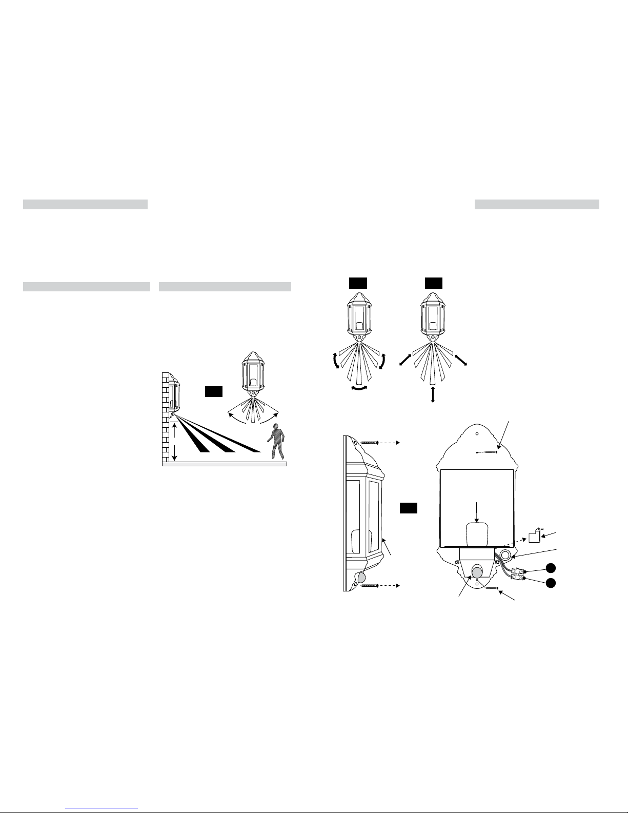
to install your PIR lantern you should note that
movement across the scan area is more eective
than movement directly towards or away from the
sensor (refer to Fig. 2 below).
If movement is made walking directly towards or
away from the sensor and not across the apparent
detection range will be substantially reduced (refer
to Fig. 3 below).
INSTALLATION:
Please refer to Fig. 4 below.
1) Remove the two screws at the top and bottom of
the tting and lift o the front housing.
2) Position the tting on the surface where it is to be
installed and mark the mounting hole positions.
3) Drill and plug the wall at the marked positions
ensuring you pass the cable wire through rubber
grommet.
4) Screw and x the back housing to wall with
suitable mounting screws (supplied).
5) Remove PIR terminal cover and expose the
connector block and make connections according
to the relatives symbols:
(L) Brown wire
(N) Blue wire.
Make sure that terminals are tightened securely and
that no strands of wire protrude.
6) Replace and secure the plastic PIR cover.
7) Insert suitable ES energy saving lamp.
8) Replace the front housing and tighten the screws.
9) Restore the power and switch on.
INTRODUCTION:
The half lantern incorporates a PIR (passive Infrared)
sensing device which continuously scans a preset
operating zone and immediately switches the light
on when it detects movement in that area.
This means that whenever movement is detected
within the range of the sensor the light will switch
on automatically to illuminate the area you have
selected to light. While there is movement within
range of the unit the light will remain on.
READ THIS FIRST:
Check the pack and make sure you have all of the
parts listed on the front of this booklet. If not,
contact the outlet where you bought this product.
This product must be installed by a competent
person in accordance with the current building
and IEE wiring regulations.
As the buyer, installer and/or user of this product it
is your own responsibility to ensure that this tting
is t for the purpose for which you have intended
it. Eterna lighting cannot accept any liability for
loss, damage or premature failure resulting from
inappropriate use.
This product is designed and constructed according
to the principles of the appropriate British Standard
and is intended for normal domestic service. Using
this tting in any other environments may result in a
shortened working life.
Switch o the mains before commencing installation
and remove the appropriate circuit fuse or lock o
MCB.
This unit is suitable for outdoor use.
This product is designed for permanent connection
to xed wiring: this must be a suitable circuit
(protected with the appropriate MCB or fuse).
Before making xing hole(s), check that there are no
obstructions hidden beneath the mounting surface
such as pipes or cables.
Make sure that the xings are strong enough to
support the considerable weight of the tting and
hold it rigidly.
The lamp must be positioned so that there is at least
0.5m (500mm) between the bulb and any illuminated
surface.
When making connections ensure that the terminals
are tightened securely and that no strands of wire
protrude. Check that the terminals are tightened
onto the bared conductors and not onto any
insulation.
WARNING: This prodct becomes hot!
This product is not intended to be used by children
and persons with sensory, physical and/or mental
impairments that would prevent them from using it
safely.
IMPORTANT - Always switch o the mains power
before changing the lamp.
You are advised at every stage of your installation to
double-check any electrical connections you have
made. After you have completed your installation
there are electrical tests that should be carried out,
these tests are specied in the current IEE wiring and
building regulations.
This product is double insulated, do not connect any
part to earth.
WHERE TO FIT YOUR PIR HALF LANTERN:
To achieve best results we suggest you take the
following points into consideration:
Do not mount on a surface that has vibration.
Ideally the PIR half lantern should be mounted 1.8
to 2.5 metres (6 to 8ft) above the area to be scanned
(refer to Fig. 1 below).
To avoid damage to the unit do not aim sensor
towards the sun.
Avoid positioning the sensor unit adjacent to a
bright light source which may prevent the unit from
operating when the lux control is set to operate in
dark conditions.
Avoid nuisance false triggering by directing sensor
away from:
Trees and shrubs
Reective surfaces such as smooth white walls
Swimming pools
Heat sources such as boiler ues
The PIR sensor scanning specications
(approximately 12 metres at 120°) may vary slightly
depending on the mounting height and location.
1.8-2.5M
4M 8M 12M
120˚
Appr.