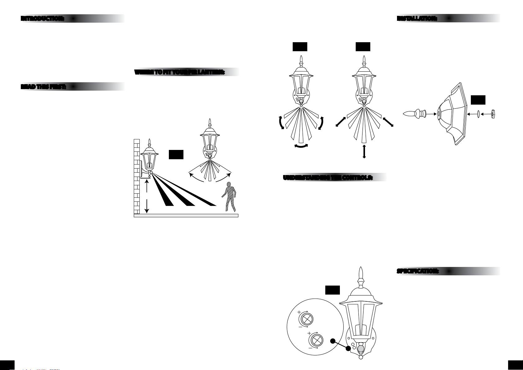
If movement is made walking directly towards or
away from the sensor and not across the apparent
detection range will be substantially reduced. (Refer
to Fig. 3 below).
UNDERSTANDING THE CONTROLS:
(Referring to Fig. 4 below)
ADJUSTING THE DURATION TIME:
The length of time that the light remains switched on
after activation can be adjusted from (10±5) seconds
to (4±1) minutes. Rotating the TIME knob from (+) to
(-) (clockwise) will reduce the time duration.
Note: Once the light has been triggered by the PIR
sensor any subsequent detection will start the timed
period again from the beginning.
ADJUSTING THE SENSITIVITY:
The sensitivity means the maximum distance which
PIR Sensor can be triggered by movement body.
Turning the SENS knob from (+) to (-) anti-clockwise
will decrease the sensitivity.
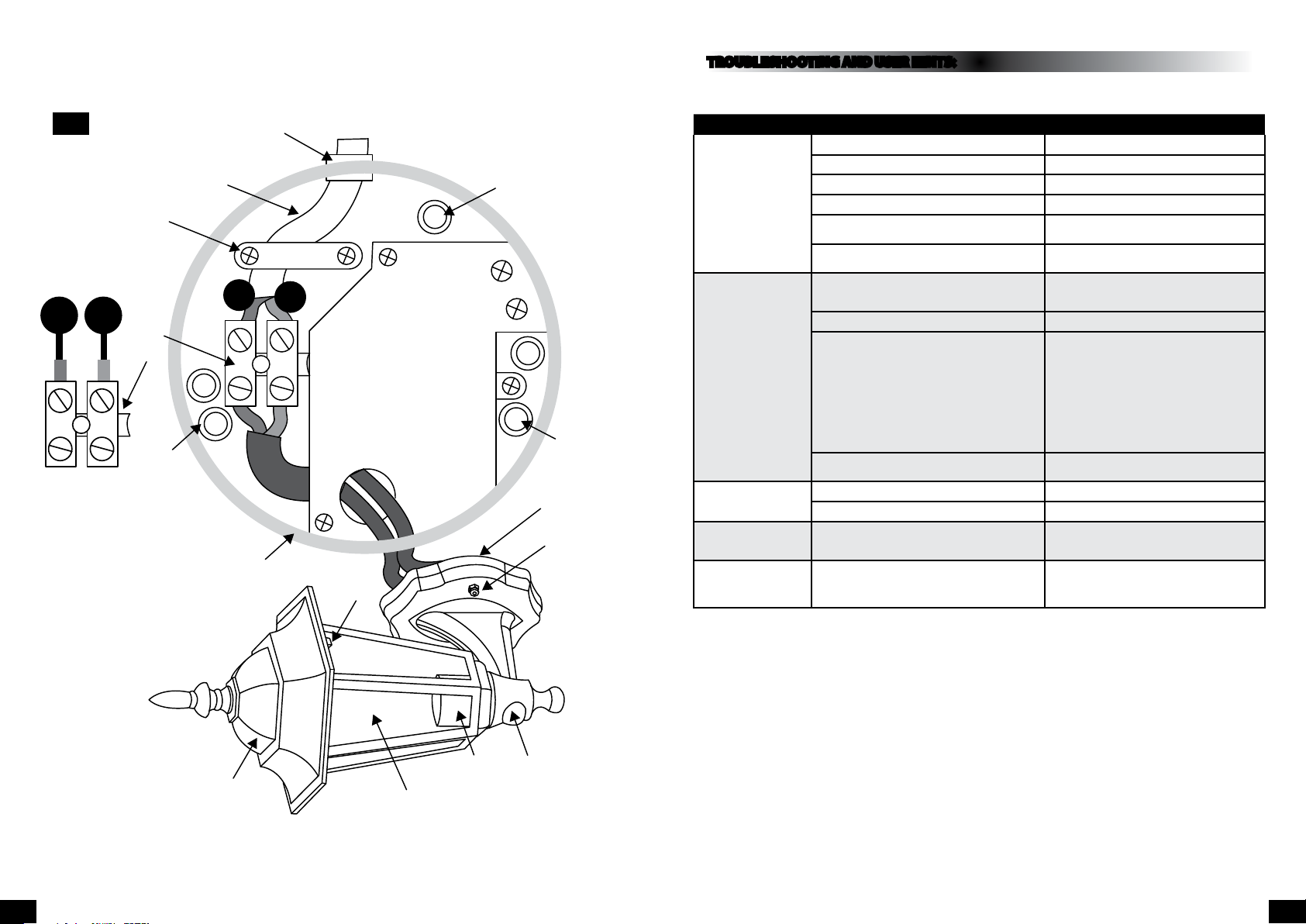
INSTALLATION:
IMPORTANT: DO NOT INVERT THE LANTERN.
When installing the PIR lantern, please refer to
Fig. 6 on page 4.
1) Switch o the mains power before commencing
installation.
2) Re-x the nial on the lantern lid as shown in
Fig. 5 below.
3) Un-screw the xing nuts, remove the wiring box
and terminal block, check that there is a rubber
gasket (at back of wiring box). Use the wiring box
to mark the position of xing.
4) Drill and plug the wall at the marked positions,
and x the wiring box to the wall with suitable
mounting screws.
5) Pass power cable through rubber grommet and
connect to the terminal block (see the relative
symbols on Fig. 6 on page 4).
6) Position lantern on wiring box and secure with
xing nut, ensure gasket rubber is in position and
do not over-tighten.
7) Fit suitable lamp.
8) Fit the transparent lens back in and t the lid
onto the body and secure with the two screws
provided.
SPECIFICATION:
• Detection range: Approx.110° (horizontal),
Max. 10 metres
• Duration time: from (10± 5) sec. (4±1)
minutes adjustable
• Sensitivity adjustable
• Weatherproof: IP44
• Voltage: 230V ~ 50 Hz
• Wattage: Fitting is rated at 60W max
INTRODUCTION:
The lantern incorporates a PIR (passive Infra red)
sensing device which continuously scans a preset
operating zone and immediately switches the light
on when it detects movement in that area.
This means that whenever movement is detected
within the range of the sensor the light will switch
on automatically to illuminate the area you have
selected to light. While there is movement within
range of the unit the light will remain on.
READ THIS FIRST:
Check the pack and make sure you have all of the
parts listed on the front of this booklet. If not,
contact the outlet where you bought this product.
This product must be installed by a competent
person in accordance with the current building
and IEE wiring regulations.
As the buyer, installer and/or user of this product it
is your own responsibility to ensure that this tting
is t for the purpose for which you have intended
it. Eterna lighting cannot accept any liability for
loss, damage or premature failure resulting from
inappropriate use.
This product is designed and constructed according
to the principles of the appropriate British Standard
and is intended for normal domestic service. Using
this tting in any other environments may result in a
shortened working life.
Switch o the mains before commencing installation
and remove the appropriate circuit fuse or lock o
MCB.
This unit is suitable for outdoor use.
This product is designed for permanent connection
to xed wiring: this must be a suitable circuit
(protected with the appropriate MCB or fuse).
Before making xing hole(s), check that there are no
obstructions hidden beneath the mounting surface
such as pipes or cables.
Make sure that the xings are strong enough to
support the considerable weight of the tting and
hold it rigidly.
The lamp must be positioned so that there is at least
0.5m (500mm) between the bulb and any illuminated
surface.
When making connections ensure that the terminals
are tightened securely and that no strands of wire
protrude. Check that the terminals are tightened
onto the bared conductors and not onto any
insulation.
This product is not intended to be used by children
and persons with sensory, physical and/or mental
impairments that would prevent them from using it
safely.
IMPORTANT - Always switch o the mains power
before changing the lamp.
You are advised at every stage of your installation to
double-check any electrical connections you have
made. After you have completed your installation
there are electrical tests that should be carried out,
these tests are specied in the current IEE wiring and
building regulations.
WHERE TO FIT YOUR PIR LANTERN:
To achieve best results we suggest you take the
following points into consideration:
Do not mount on a surface that has vibration
Ideally the PIR bulkhead light should be mounted 1.8
to 2.5 metres (6 to 8ft) above the area to be scanned
(refer to g. 1 below).
To avoid damage to the unit do not aim sensor
towards the sun.
Avoid positioning the sensor unit adjacent to a
bright light source which may prevent the unit from
operating when the lux control is set to operate in
dark conditions.
Avoid nuisance false triggering by directing sensor
away from:
Trees and shrubs.
Reective surfaces such as smooth white walls.
Swimming pools.
Heat sources such as boiler ues.
The PIR sensor scanning specications
(approximately 10 metres at 110°) may vary slightly
depending on the mounting height and location.
The detection range of the unit may also alter
with temperature change. Before selecting a place
to install your PIR lantern you should note that
movement across the scan area is more eective
than movement directly towards or away from the
sensor. (Refer to Fig. 2 opposite).
2M
2M 6M 10M
110˚
Appr.
TIME
SENS
Blue
(Power Cable)
N
Brown
(Power Cable)
L
Fixing
Nuts x2
Wiring
Box
Rubber
Gasket
Fixing
Wall
Screw
Fixing
Wall
Screw
Rubber
Grommet
PIR Sensor
Lampholder
Lid
Screw
x2
Transparent
Lens
Lantern
Lid
Fixing Wall
Screw
Terminal Block Cable
Clamp
Power Cable (2 Core)
L
N
Fig 1
TIME
SENS
Blue
(Power Cable)
N
Brown
(Power Cable)
L
Fixing
Nuts x2
Wiring
Box
Rubber
Gasket
Fixing
Wall
Screw
Fixing
Wall
Screw
Rubber
Grommet
PIR Sensor
Lampholder
Lid
Screw
x2
Transparent
Lens
Lantern
Lid
Fixing Wall
Screw
Terminal Block Cable
Clamp
Power Cable (2 Core)
L
N
Fig 4
2M
2M 6M 10M
110˚
Appr.
TIME
SENS
Blue
(Power Cable)
N
Brown
(Power Cable)
L
Fixing
Nuts x2
Wiring
Box
Rubber
Gasket
Fixing
Wall
Screw
Fixing
Wall
Screw
Rubber
Grommet
PIR Sensor
Lampholder
Lid
Screw
x2
Transparent
Lens
Lantern
Lid
Fixing Wall
Screw
Terminal Block Cable
Clamp
Power Cable (2 Core)
L
N
Fig 2
NOT GOOD
Fig 3
GOOD
Fig 5
2M
2M 6M 10M
110˚
Appr.
TIME
SENS
Blue
(Power Cable)
N
Brown
(Power Cable)
L
Fixing
Nuts x2
Wiring
Box
Rubber
Gasket
Fixing
Wall
Screw
Fixing
Wall
Screw
Rubber
Grommet
PIR Sensor
Lampholder
Lid
Screw
x2
Transparent
Lens
Lantern
Lid
Fixing Wall
Screw
Terminal Block Cable
Clamp
Power Cable (2 Core)
L
N
PG 3PG 2