READ THIS FIRST:
Check the pack and make sure you have all of the
parts listed on the front of this booklet. If not,
contact the outlet where you bought this product.
This product must be installed by a competent
person in accordance with the current building and
IEE wiring regulations.
As the buyer, installer and/or user of this product it
is your own responsibility to ensure that this tting
is t for the purpose for which you have intended
it. Eterna Lighting cannot accept any liability for
loss, damage or premature failure resulting from
inappropriate use.
This product is designed and constructed according
to the principles of the appropriate British Standard
and is intended for normal domestic service. Using
this tting in any other environments may result in
a shortened working life, for example where there
is prolonged periods of use or higher than normal
ambient temperatures such as lighting public or
shared spaces or in nursing / care home facilities.
This tting must be installed in accordance with the
Building Regulations. These may be obtained from
HMSO or viewed and downloaded from www.odpm.
gov.uk following the link for Building Regulations.
Switch o the mains before commencing installation
and remove the appropriate circuit fuse.
Suitable for outdoor use.
Avoid installing this unit in direct sunlight or other
light sources and where it will be out of reach.
This product is suitable for installation on surfaces
with normal ammability e.g. wood, plasterboard,
masonry. It is not suitable for use on highly
ammable surfaces (e.g. polystyrene, textiles).
Before making xing hole(s), check that there are no
obstructions hidden beneath the mounting surface
such as pipes or cables.
Do not attach to surfaces which are damp, freshly
painted or otherwise electrically conductive (e.g.
metallic surfaces).
If the location of your new tting requires the
provision of a new electrical supply, the supply
must conform with the requirements of the Building
Regulations.
This product is designed for permanent connection
to xed wiring: this should be either a suitable
lighting circuit (protected with a 5 or 6 Amp MCB or
fuse) or a fused spur (with a 3 Amp fuse) via a fused
connection unit. We recommend that the supply
incorporates a switch for ease of operation.
Make connections to the electrical supply in
accordance with the following code:
(L) Live: Brown or Red
Connect to the incoming supply live
(N) Neutral: Blue or Black
Connect to the incoming supply neutral and to the
light/load neutral terminal.
(LO) Load Live: Brown or Red
Connect to the live terminal on the light/load
This tting is double insulated, do not connect any
part to earth.
You are advised at every stage of your installation to
double-check any electrical connections you have
made. After you have completed your installation
there are electrical tests that should be carried out:
these tests are specied in the Wiring Regulations
(BS7671) referred to in the Building Regulations.
SPECIFICATION:
Power rating: 1500VA or 5 Amp inductive load at
60F
Supply voltage: 240V
Switch on/o at 30/80 lux
NPCHKIT INSTALLATION:
01) Separate the control unit from the NEMA base by
twisting anti-clockwise and pulling gently.
02) Using the wall xing bracket as a template, mark
and make the xing holes.
03) Secure the bracket in place using the 3 wall
plugs and screws supplied. If these xings are
not suitable for your installation use suitable
alternatives.
04) The wall xing bracket will accept 20 mm conduit
and ttings or a plain cable entry.
05) Ensure that the correct rated outdoor cable is
used.
06) Make connections to the NEMA socket as detailed
above.
07) Ensure that all connections are secure and that
no “whiskers” or bare wires are left free from the
terminals.
08) Ensure that the cork gasket is located on the lugs
inside the wall bracket and secure the NEMA
base socket to the bracket with the two screws
provided.
09) Ret the photocell by inserting in the base and
twisting clockwise to lock. The socket is polarised
and will only t one way.
10) Check that your light tting or other load has
been installed and connected correctly.
11) Restore the power and test the installation by
covering the control unit (the product box is
suitable), waiting approximately 1 minute for the
unit to switch on and then removing the box and
checking that the unit switches o.
NPCH INSTALLATION:
01) The photocell may be installed in a wall xing
bracket as detailed above.
02) It may also be installed with a light tting of your
choice provided the NEMA base is securely tted
with suitable xings and the connections are
made in accordance with the instructions above.
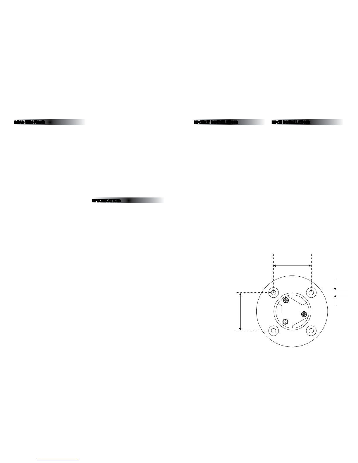
03) When xing the NEMA socket, use countersunk
screws to ensure eective sealing of the foam
gasket on the photocell unit.
04) Ensure that the socket is located in a position
where it will not be exposed to excessive heat
e.g. not directly above or in close proximity to a
lamp or ballast.
05) Make electrical connections according to the
instructions opposite.
06) After installation, conduct tests as for installation
of the complete kit. In the event of damage to the
photo control unit cover, isolate the installation
from the mains supply before unplugging.
34.5mm
36mm
4.25mm