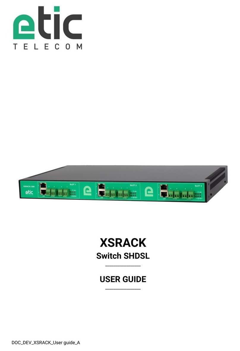
Etic Telecom RAS Series User manual

DOC_DEV_RAS_User Guide_E
RAS
Machine Access Box
_________________
USER GUIDE
_________________

DOC_DEV_RAS_User Guide_E Page 3
UE DECLARATION OF CONFORMITY
The manufacturer, ETIC Telecom –13 chemin du vieux chêne –38240 Meylan –France, Hereby declares
under sole responsibility that the listed devices conform to
-the Radio Equipment Directive (RED) 2014/53/UE,
-the Restriction of the use of certain Hazardous Substances (RoHS) Directive 2011/65/UE.
Type of device: Machine Access Box - RAS
Models:
RAS-E-400, RAS-E-2XX, RAS-EW-400, RAS-EW-2XX, RAS-EC-400, RAS-EC-2XX, RAS-ECW-400, RAS-ECW-2XX,
RAS-E-100, RAS-EW-100, RAS-C-100
The harmonized standards to which these devices comply are:
Standard
Title
EN 61000-6-2 2006
Immunity:
EN61000-4-2 Electrostatic Discharge
EN61000-4-3 RF Radiated Immunity
EN61000-4-4 EFT/Burst Immunity
EN61000-4-5 Surge Immunity
EN61000-4-6 RF Conducted Immunity
EN61000-4-8 Power Frequency Magnetic Field Immunity
EN 61000-6-4 2007
A1/2011
Emission:
EN55032 Radiated and conducted emission
EN 301 489-1 V1.9.2
EN 301 489-3 V1.6.1
EN 301 489-7 V1.3.1
EN 301 489-17 V2.2.1
EN 301 489-24 V1.5.1
Radio - EMC
EN 301 511 V9.0.2
EN 301 908-1 V6.2.1
EN 301 908-2 V6.2.1
EN 300 328 V1.9.1
EN 301893 V1.8.1
Radio - Spectrum
EN 62368-1 2014
EN 62311 2008
Safety and Health
Date: 7th February 2019
Philippe Duchesne
Technical Director

Page 4 DOC_DEV_RAS_User Guide_E
FCC/IC Regulatory notices (RAS-X-100 models)
This device complies with Part 15 of the FCC. Operation is subject to the following two conditions: (1) this
device may not cause interference, and (2) this device must accept any interference, including interference
that may cause undesired operation of the device.
This equipment has been tested and found to comply with the limits for a Class A digital device, pursuant to
Part 15 of the FCC Rules. These limits are designed to provide reasonable protection against harmful
interference when the equipment is operated in a commercial environment. This equipment generates, uses,
and can radiate radio frequency energy and, if not installed and used in accordance with the instruction manual,
may cause harmful interference to radio communications. Operation of this equipment in a residential area is
likely to cause harmful interference in which case the user will be required to correct the interference at his
own expense.
Caution: ETIC Telecom has not approved any changes or modifications to this device by the user. Any changes
or modifications could void the user's authority to operate the equipment.

TABLE OF CONTENTS
DOC_DEV_RAS_User Guide_E Page 5
OVERWIEW....................................................................................................................................7
1Purpose of this manual .................................................................................................................................... 7
2Products Identification ..................................................................................................................................... 7
3Specifications.................................................................................................................................................... 8
4Product overview ............................................................................................................................................ 12
4.1 Main functions of the RAS .................................................................................................................. 12
4.2 RAS organization ................................................................................................................................. 13
4.3 The M2Me_Connect connection......................................................................................................... 14
4.4 Benefits of the M2Me_Connect service ............................................................................................. 15
5Use cases ........................................................................................................................................................ 16
INSTALLATION ...........................................................................................................................17
1Description ...................................................................................................................................................... 17
1.1 Dimensions .......................................................................................................................................... 17
1.2 Connectors........................................................................................................................................... 18
1.3 Push-buttons........................................................................................................................................ 23
1.4 LED indicators...................................................................................................................................... 24
2Safety instructions .......................................................................................................................................... 25
3DIN rail mounting ............................................................................................................................................ 26
4Cooling............................................................................................................................................................. 26
5Power supply................................................................................................................................................... 27
6Earthing ........................................................................................................................................................... 27
7RS232 serial connection................................................................................................................................. 27
8RS485 serial connexion ................................................................................................................................. 27
9Digital input and output .................................................................................................................................. 28
10 Connecting the RAS to the cellular network .............................................................................................. 28
10.1 Controls before installing the RAS.................................................................................................. 28
10.2 Cellular antenna ............................................................................................................................... 29
10.3 Coaxial cable.................................................................................................................................... 29
10.4 Cellular service subscription ........................................................................................................... 29
10.5 Installing the SIM card..................................................................................................................... 30
10.6 Controlling the conformance of the connection ............................................................................ 31
PREPARING THE SETUP............................................................................................................33
1Connecting a PC for configuration ................................................................................................................ 33
1.1 Overview............................................................................................................................................... 33
1.2 First configuration ............................................................................................................................... 34
1.3 Changing the configuration later ........................................................................................................ 34
2Access to the administration server through the WAN interface ................................................................ 35
3Working with HTTPS....................................................................................................................................... 35
4Temporary return to the factory settings ...................................................................................................... 36
5Restoring the factory settings........................................................................................................................ 36
6Protecting the access to the administration server...................................................................................... 37
USING THE WIZARD...................................................................................................................39
1Use cases ........................................................................................................................................................ 39
2Use case 1 ....................................................................................................................................................... 40

TABLE OF CONTENTS
Page 6 DOC_DEV_RAS_User Guide_E
3Use case 2 ....................................................................................................................................................... 41
4Use case 3 ....................................................................................................................................................... 42
5Use case 4 ....................................................................................................................................................... 43
6Use case 5 ....................................................................................................................................................... 44
7Use case 6 ....................................................................................................................................................... 45
8Example: Access to the Internet via the Ethernet WAN network ................................................................. 46
ADVANCED SETUP.....................................................................................................................51

OVERVIEW
DOC_DEV_RAS_User Guide_E Page 7
OVERWIEW
1Purpose of this manual
The present user guide describes the features and the installation of the Machine Access Boxes family (RAS).
In this document, these products are named « RAS ».
2Products Identification
This family of Machine Access Boxes consists of these models:
RAS-E-400, RAS-E-2XX,
RAS-EW-400, RAS-EW-2XX,
RAS-EC-400, RAS-EC-2XX,
RAS-ECW-400, RAS-ECW-2XX,
RAS-E-100, RAS-EW-100, RAS-C-100
The main features are summarized below:
Models
RAS-
E-100
EW-100
C-100
E-400
E-220
EW-400
EW-220
EC-400
EC-220
ECW-400
ECW-220
WAN Ethernet
•
•
•
•
•
•
•
•
•
•
WAN Cellular
(-HG, -HW : 3G+,
-LE : 4G)
•
•
•
•
•
Wi-Fi 2.4 and 5 GHz
•
•
•
•
•
LAN Ethernet
10-100 Mb/s
1
1
1
4
2
4
2
4
2
4
2
Serial link
RS232 /RS485
•
•
•
•
USB
•
•
•
•
•
•
•
•
GPS option
(with ANT405)
•
•
•
•
•
•
•
•
2 power inputs
•
•
•
•
•
•
•
•
Power supply
VDC
12-24
12-24
12-24
12-48
12-48
12-48
12-48
12-48
12-48
12-48
12-48
2 SIM readers
•
•
•
•
Digital input
1
1
1
1
1
1
1
1
Digital output
1
1
1
1
1
1
1
1
In the remainder of this document the term RAS-X is used indifferently for RAS-C, RAS-E, RAS-EC, RAS-EW
and RAS-ECW.

OVERVIEW
Page 8 DOC_DEV_RAS_User Guide_E
3Specifications
General characteristics
Dimensions
RAS-X-100: 120 x 37 x 88 mm (h,w,d)
Other RAS: 135 x 47 x 115 mm (h,w,d)
Weight
Max 0.65 kg
Casing
Metallic
RAS- X-100: IP41 –IEC60529
Other RAS: IP20 –IEC60529
DIN rail mounting
Temperature
Non-operating: -40°/ + 85°C
Operating: -20°/ + 70°C
Humidity
5 to 95 % relative (non-condensing)
Power supply
Protected against reverse polarity
RAS-X-100: Nominal: 12-24 VDC (min 10 VDC - max 30 VDC)
Other RAS: Nominal: 12-48 VDC (min 10 VDC - max 60 VDC)
2 points Phoenix connector
Consumption
RAS-E: 2W
RAS-EC et RAS-EW: 5W
RAS-ECW: 8W
EMC
Immunity EN61000-6-2:
EN61000-4-2 : ESD : 4 kV contact –8kV air
EN61000-4-3 : RF - radiated: 10V/m < 2 GHz
EN61000-4-4 : Burst
EN61000-4-5 : Surge
EN61000-4-6 : RF - conducted
EN61000-4-8 : Magnetic fields
Emission EN61000-6-4:
EN 55032: RF - conducted and radiated
FCC:
RAS-X-100 : FCC Part 15
Electrical safety
IEC/EN 62368-1
RAS-X-100 : CB FR_704843
Hazardous substances
2011/65/UE (RoHS)
REACH

OVERVIEW
DOC_DEV_RAS_User Guide_E Page 9
WAN network
Ethernet
RJ45
Auto: 10/100 full & half duplex MDI/MDI-X
4G/3G+
-LE : 4G LTE Europe
LTE bands: B1, B2, B3, B4, B5, B7, B8, B20
UMTS bands: B1, B2, B5, B8
GSM bands: 850/900/1800/1900
-CH : 4G LTE China
LTE bands: B1, B3, B8, B38, B39, B40, B41
UMTS bands: B1, B5, B8, B9
GSM bands: 900/1800
-HG : 3G+ HSPA worldwide (except. North America)
UMTS bands: B1, B2, B5, B8
GSM bands: 850/900/1800/1900
-HW : 3G+ HSPA worldwide
UMTS bands: B1, B2, B4, B5, B6, B8, B19
GSM bands: 850/900/1800/1900
Max data rate 4G: UL @ 50 Mbps and DL @ 100Mbps
Max data rate 3G+: UL @ 5,7 Mbps and DL @ 21 Mbps
Max data rate 2G: UL @ 237 Kbps and DL @ 237 Kbps
Antenna connector female SMA
Wi-Fi
Client 2.4 and 5 GHz
802.11 a/b/g/n
Antenna connector female RP-SMA
LAN network
Ethernet
RJ45: 1 to 4 ports depending on model
Auto: 10/100 full & half duplex MDI/MDI-X
Wi-Fi
Access point 2,4 and 5 GHz
802.11 a/b/g/n
Antenna connector female RP-SMA
Routing / @IP
IP Routing
Routing tables
Static routes
RIP or OSPF
Address translation (DNAT, SNAT, NAT 1:1)
IP@ assignment
WAN interface: DHCP client or fixed IP
LAN interface: DHCP server
DNS
WAN interface: compatible with DYNDNS, No-IP or ETIC DNS
LAN interface: DNS relay & server
Redundancy
VRRP RFC 3768 protocol
Multi WAN for backup on some RAS models

OVERVIEW
Page 10 DOC_DEV_RAS_User Guide_E
Security
VPN tunnel
OpenVPN (TLS/SSL), IPSEC, L2TP/IPSEC, PPTP
Shared key or X509 certificate
Encryption 3DES & AES 128-192-256
Authentication: MD5 & SHA-1
Up to 10 VPN tunnels
(mix OpenVPN IPSEC allowed)
Firewall
Stafefull packet inspection (SPI: 50 rules)
IP@ and ports filtering
Log
Timestamped
Events: connection, restart, alarms
Alarms
Digital input: email, SMS, SNMP trap
Digital output: Power supply failure, user connection…
Serial gateways
Gateways
Raw TCP client
Raw TCP server
Raw UDP
Raw Multicast
ModBus TCP client to Modbus RTU/ASCII slave (for master PLC)
Modbus TCP server to Modbus RTU/ASCII master (for slave PLC)
Telway/XIP to Unitelway slave (for master PLC)
Telnet RFC 2217
RS232/RS485
Data rate : 1200 to 115200 kb/s, 10 or 11 bits, parity N / E / O
RS232 : RJ45
RS485 : 2 points Phoenix connector
USB
1 port USB host
PPP client
Misc.
SNMP
Supported MIBs:
RFC1213-MIB (MIB-2)
ETIC-TELECOM-MIB-1
SNMP traps
Configuration
Web server
Management
Save and restore configurations
Reset product to return to factory configuration

OVERVIEW
DOC_DEV_RAS_User Guide_E Page 11
M2Me solution
Users
Up to 100 remote users
Alarms
Compatible with «EticDisplay» solution
Security
RAS access: Login & Password and Certificate (optional)
Single RAS product key required for the remote user
Customizable LAN machine network access rights
Communication
Secured connection on to the M2Me_Connect service
OpenVPN
Management
« Collect & Alert »
Recording on USB flash drive, µSD card or internal memory
Email and SMS alarms
« Pack SMS »
Options managed from the client area of the WEB site
M2Me client
PC: All OS versions up to W10
Smartphone and Tablet: Android et iOS
M2Me_Connect
VPN Tunnel Secure interconnection service
RAS Manager
RAS fleet management centralised (option)

OVERVIEW
Page 12 DOC_DEV_RAS_User Guide_E
4Product overview
4.1 Main functions of the RAS
Remote maintenance of machines using the M2Me_Connect service
The RAS family allows to connect easily and safely a machine to a remote PC, through the M2Me_Connect
Internet cloud service, for operation like remote maintenance.
When the remote PC is connected, the remote user can exchange any kind of data with each device of the
machine network as if his PC was directly connected to the machine network.
Ethernet or serial devices
The machine can consist of one or several devices connected through an Ethernet machine network or
connected through a serial RS232-RS485 interface.
The RAS can be connected to the Internet through a cellular network, a Wi-Fi network or a factory
network
An Up-to-date IP router for particular situations
When using the Expert mode set-up, the RAS becomes a powerful IP router-RAS-firewall for industrial IP
networks applications.

OVERVIEW
DOC_DEV_RAS_User Guide_E Page 13
4.2 RAS organization
The RAS connects to the devices network (called machine) and on the other hand to the Internet.
The RAS provides two IP interfaces: The WAN interface to reach the Internet and the LAN interface to connect
the machine.
WAN interface:
Depending on the model, the RAS provides the following interfaces to reach the Internet:
WAN interfaces
RAS-E
RAS-EW
RAS-C
RAS-EC
RAS-ECW
Ethernet
⚫
⚫
⚫
⚫
Wi-Fi
⚫
⚫
Cellular
⚫
⚫
⚫
The network connected to the WAN interface is called the WAN network or factory network.
LAN interface:
Depending on the model, the RAS provides 1 to 4 switched Ethernet ports to connect the devices of the
machine.
That network is called the machine network.
1 serial RS232 and 1 serial RS485 interfaces are provided optionally.
Firewall
The firewall filters data between the WAN interface or any VPN interface on one hand, and the LAN interface
on the other hand.
The firewall filters source and destination IP addresses, but also remote users according to their identity.

OVERVIEW
Page 14 DOC_DEV_RAS_User Guide_E
4.3 The M2Me_Connect connection
Connecting a remote PC to a machine in any situation
M2Me Connect service is an ideal solution when a « machine », made of a set of devices connected to the
same LAN, is located in a private network (such as a Factory network).
Let’s take the example of a « machine » made of a set of connected devices and connected to the Factory
Network via a RAS-E.
Assuming that an expert is willing to remotely have access to the machine for breakdown diagnosis, technical
data acquisition, Web page display, file or program refreshment, M2Me Connect service enables the remote
operator to have access to the machine even if the machine does not have any public IP address.
Operation
When it is powered on or if the digital input is enabled, the RAS settles a secured VPN connection onto the
M2Me Connect cloud service.
The remote PC is authenticated by the M2Me Cloud service.
If the RAS provides two WAN connections (cellular and Ethernet, for example), it establishes the most
favorable connection as defined in the configuration of the RAS (In principle Ethernet with cellular backup).
On the other hand, the remote user launches its M2Me secure software and settles a secured VPN connection
to the M2Me Cloud.
The directory offered by M2Me_Secure is helping the user to point the remote machine onto which he wants
to be connected.
The RAS verifies then after that the remote user is allowed to be connected by checking its login & password
and as an option the certificate of the remote PC.
The RAS grants to the remote user access rights according to its identity.
In order to warrant the level of security requested by industrial application, connection from PC to RAS is fully
encrypted and cannot be recovered even in case of intrusion onto the M2Me Connect cloud service.

OVERVIEW
DOC_DEV_RAS_User Guide_E Page 15
4.4 Benefits of the M2Me_Connect service
Outgoing connection
M2Me connection onto the Internet is powered from the RAS. This non-intrusive solution is better admitted
than an ingoing connection from the Internet onto the Machine.
Private & dynamic IP address
The machine connected into a factory network or connected to the Internet via a cellular network does not
have a public IP address. M2Me solution does not require a public IP address to settle a connection onto the
machine.
Access to each device of the machine
M2Me teleport your PC onto the machine network enabling you to have access to each device of the
machine as if you were in front of the machine.
Machine with Ethernet or serial connection
The family of RAS enables you to set up a connection to any type of PLC offering an Ethernet or a serial
connectivity.
Simple configuration
Html configuration Server is delivered with a Wizard which gives an intuitive way of configuring the device.
Simple Operation
M2Me Secure software offers e set of directories for the remote machines. One click is enough to be
connected.
Security of customer network (Factory or WAN network)
RAS enables the remote operator to have access only to the machine network protecting the factory network
from any intrusion.
Machine & Device Access protection
A remote user can access to the machine if and only if its identification (login & password) has been
preregistered in the RAS.
An extra security option is offered. RAS can also demand the certificate installed in the PC of the remote
user.
The RAS can also give restricted access to the machine network giving access only to certain devices of the
machine and not to all.
Internet & Security
The flow of information passing through the M2Me connection is fully encrypted and requires authentication
to the M2Me server of both the PC of the remote user and the RAS. A third party cannot consequently have
access to the machine preserving the integrity of the industrial process to be remote maintained.

OVERVIEW
Page 16 DOC_DEV_RAS_User Guide_E
5Use cases
There are different ways to connect the RAS to the Internet and to the machine depending on the situation
which is encountered and also on the RAS model.
At the setup time, the wizard proposes all or part of these situations according to the model; just select the
appropriate situation and be guided to implement the Internet connection and the list of users.
The other functions can be configured with the Expert mode.
Use case
Internet access
Description
1
Any
models
Factory network
The Machine is
connected to the Internet
via the Factory network
through the RAS.
2
Any
models
Factory network
The machine belongs to
the Factory network.
3
RAS-EC
RAS-ECW
Cellular network
The machine is
connected to the Internet
via a cellular network.
4
RAS-EW
RAS-ECW
Wi-Fi
The machine is
connected to the Internet
via a Wi-Fi network.
5
RAS-EC
RAS-ECW
Factory network
+
cellular
network
The machine is
connected to the Internet
via the Factory network
and, if it is not available,
via a cellular network.
6
RAS-ECW
Wi-Fi
+
cellular
network
The machine is
connected to the Internet
via the Wi-Fi network
and, if it is not available,
via a cellular network.

INSTALLATION
DOC_DEV_RAS_User Guide_E Page 17
INSTALLATION
1Description
1.1 Dimensions
All models except RAS-X-100
RAS-X-100
37 mm
35 mm Din rail
axis
60 mm
88 mm
120 mm

INSTALLATION
Page 18 DOC_DEV_RAS_User Guide_E
1.2 Connectors
RAS-E-400
RAS-EW-400
RAS-E-220
RAS-EW-220

INSTALLATION
DOC_DEV_RAS_User Guide_E Page 19
RAS-EC-400
RAS-ECW-400
RAS-EC-220
RAS-ECW-220

INSTALLATION
Page 20 DOC_DEV_RAS_User Guide_E
RAS-E-100
RAS-EW-100
RAS-C-100
2 pos screw block
Power supply
Ethernet WAN
Push button B1
Ethernet LAN
Reset push
button on the rear
pannel
Ground terminal
Ethernet WAN
Ethernet LAN
Wi-Fi
2 pos screw block
Power supply
Reset push button
on the rear pannel
Push button B1
Ground terminal
Ethernet LAN
Cellular
Carte SIM sur la
face arrière
2 pos screw block
Power supply
Push button B1
Reset push button
on the rear pannel
Ground terminal
Other manuals for RAS Series
1
This manual suits for next models
15
Table of contents
Other Etic Telecom Network Hardware manuals
Popular Network Hardware manuals by other brands
Positron
Positron G1002-M Quick installation guide
NETGEAR
NETGEAR ReadyDATA 5200 installation guide
Techroutes
Techroutes TSR 2800-20-DC installation manual
ADTRAN
ADTRAN T200 H2TU-R Installation and Maintenance
ADTRAN
ADTRAN Total Access 850 Installation and Maintenance
Fusion
Fusion Mini Bonder Getting started guide


