manuals.online logo
Brands
  1. Home
  2. •
  3. Brands
  4. •
  5. DCB
  6. •
  7. Network Hardware
  8. •
  9. DCB PTT24 User manual

DCB PTT24 User manual

PTT-24 Push-To-Talk
Lockout Device
Front View
Rear View
FEATURES
Use to de-key radios on Busy Idle T1 trunks
Industrial temperature rated -40 to +70 C
50 Telco amphenol in and out connectors
Push button switches to select control port
Toggle switch to select 12 or 24 E leads
Switch to test lockout function
The selected control port, when asserted, de-
asserts the other 11 or 23 E leads
Audible alarm with audio shutoff button
Alarm input to force lockout function
Supports Tie Line Types I, II IV and V
1U high, 19” rackmount
-48 VDC dual power inputs, diode protected from
each other
DESCRIPTION
The PTT-24 is a Push-to-Talk lockout device. It is
used with multiple E&M circuits linked to radios. The PTT-24
solves the problem of radio transmitters bein locked into a
Transmit ON state when a T1 circuit fails. Many T1 trunk
lines will o into a busy condition when the T1 trunk fails.
This causes the E&M leads to lock in an ON state, which
causes radio transmitters to lock in the ON state.
12 or 24 E&M ports are wired throu h the PTT
Lockout unit. A front panel to le switch is used to select 12
or 24 port operation. A 2 position push button switch is used
to select the control port. The Power LED
flashes if an invalid control port number is
selected.
Based on the selected control port
(via the front panel) the PTT Lockout
device will detect a closure to round on
that port and de-assert all the other ports.
E&M Type III is not supported.
In the PTT-24 12 port mode,
selectin control channel 1 throu h 12 will
select one of the even numbered leads 26
thou h 48 as the control port. The other 11
even numbered leads will be de-asserted if
the control port is asserted. All other leads
are passed strai ht throu h.
In the PTT-24 24 port mode,
selectin control channel 1 throu h 24 will
select one of the leads 26 thou h 48 as the
control port. The other 23 leads will be de-
asserted if the control port is asserted. All
other leads are passed strai ht throu h.
If the PTT-24 were to lose power,
the E-leads will be in a pass throu h mode
as thou h the PTT-24 is only a “lump in
the cable”.
Lockout can be tri ered by the
E&M control port bein activated or the
alarm input. For both the control port and
the alarm input, there is a delay of 20
milliseconds before the lockout occurs. The
de-activation delay is 5 seconds. The de-
activation delay eliminates lockout
“chatterin ” on/off/on/off, etc.
Leads 1 thou h 25 and 50 of the 50
pin amphenol Telco connector are passed
strai ht throu h.
PTT-2 – Push-To-Talk Lockout Device
SPECIFICATIONS
General
Front Panel (these are approximate placements, subject to
relocation):
- To le switch to select 12 or 24 E&M ports
- Push button switch to select port 1 to 24 for PTT Lockout control
- Test switch, momentary, to test lockout function
- Front panel switch to kill an audio alarm that will sound when/if
the control port activates
- Green Power LED (flashes if an invalid control port number is
selected, i.e. 00, 25, etc.)
- Red "ALARM" LED to indicate the PTT Lockout switch is activated
- Yellow "ACO" LED to indicate the ALARM CUT OFF is on
Rear Panel:
- 2 power inputs for -48 VDC power, diode protected between the 2
power inputs to avoid power feed back
- Alarm Input (dry contact closure) to externally activate the PTT
Lockout function and/or test the unit
- Alarm output dry contact
- Female 50 pin telco connector from the channel bank, screw
connection and cable tie type
- Male 50 pin telco from the PTT lockout to Transmitter side of the
circuit, screw connection and cable tie type
Physical/Electrical
Standalone or rack mountin
Power requirements: -48 VDC
19” W x 10” D x 1 ¾” H
3 pounds
Environmental
Operational Temperature: -40 to +70 C
Stora e Temperature: -50 to +75 C
Humidity: <95% Non-condensin
Pinout of the 50-Pin Telco Connectors
Data Comm for Business, Inc.
2949 CR 1000 E
Dewey, IL 61840
oice 8004DCBNET
(800.432.2638)
Fax 217.897.1331
Info www.dcbnet.com/contact.html
Web www.dcbnet.com

Other manuals for PTT24

1

Other DCB Network Hardware manuals

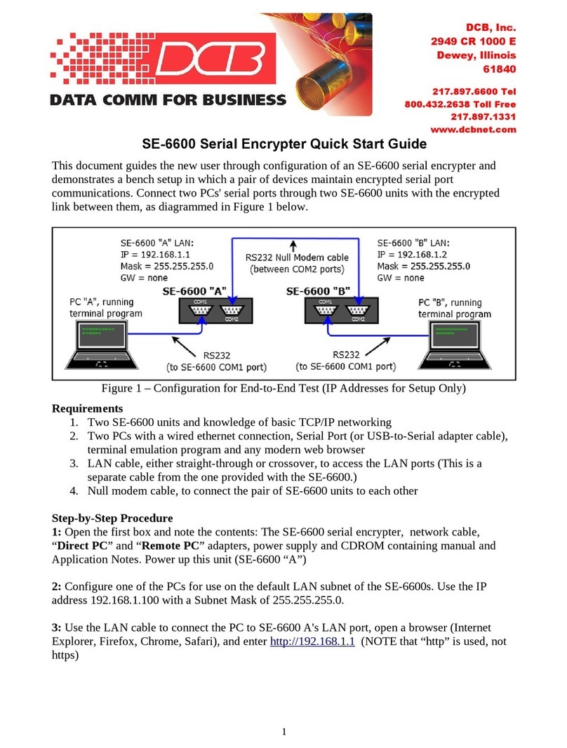
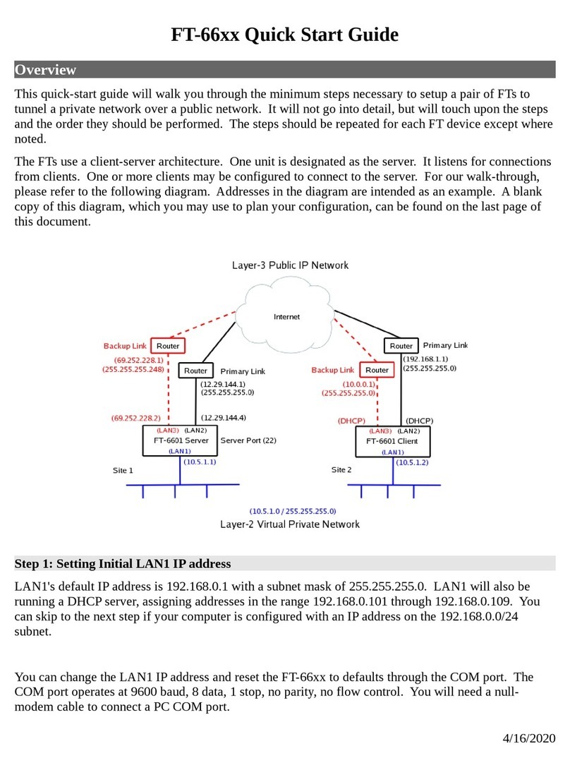
DCB SE-6600 User manual

DCB

DCB SE-6600 User manual

DCB BROADCAST POLLING FRAD BPF-2 BU User manual

DCB

DCB BROADCAST POLLING FRAD BPF-2 BU User manual

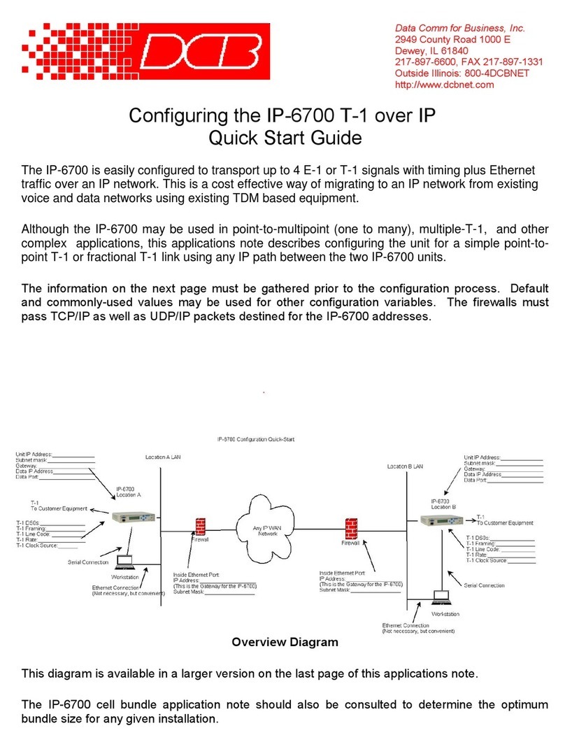
DCB IP-6700 User manual

DCB

DCB IP-6700 User manual

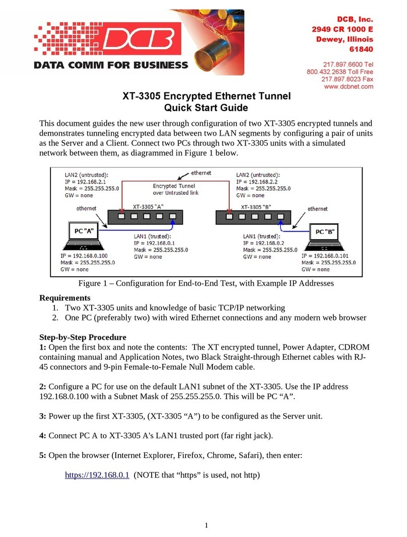
DCB XT-3305 User manual

DCB

DCB XT-3305 User manual

DCB FT-66 Series User manual

DCB

DCB FT-66 Series User manual

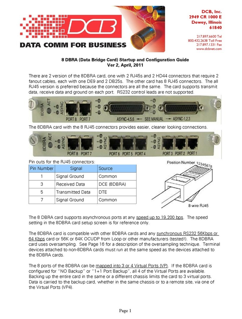
DCB 8 DBRA User manual

DCB

DCB 8 DBRA User manual

Popular Network Hardware manuals by other brands

Metrodata PacketLINK user manual

Metrodata

Metrodata PacketLINK user manual

Amtran Qualcomm QCS8250 user guide

Amtran

Amtran Qualcomm QCS8250 user guide

Dell MC SD-WAN Edge 3400 Advanced Activation guide

Dell

Dell MC SD-WAN Edge 3400 Advanced Activation guide

MSTRONIC MIT-904P user manual

MSTRONIC

MSTRONIC MIT-904P user manual

HP 634041-006 Deployment guide

HP

HP 634041-006 Deployment guide

Datacom Systems Tap Series Fast start guide

Datacom Systems

Datacom Systems Tap Series Fast start guide

UltrArmor UA3 Series user guide

UltrArmor

UltrArmor UA3 Series user guide

Dell PowerEdge XR4000z Installation and service manual

Dell

Dell PowerEdge XR4000z Installation and service manual

NorcoSEA KVM-1501COMBO-S user manual

NorcoSEA

NorcoSEA KVM-1501COMBO-S user manual

KEBCO COMBICOM instruction manual

KEBCO

KEBCO COMBICOM instruction manual

Blue Coat ProxySG 300 Series Replacing the Compact Flash Card

Blue Coat

Blue Coat ProxySG 300 Series Replacing the Compact Flash Card

Pioneer DRM-6NX Release notes

Pioneer

Pioneer DRM-6NX Release notes

Blue Coat ProxySG 9000 Series COMPLIANCE GUIDE

Blue Coat

Blue Coat ProxySG 9000 Series COMPLIANCE GUIDE

CITA CI-ERD128-64-I user manual

CITA

CITA CI-ERD128-64-I user manual

Cisco NSS4100 - Gigabit Storage System release note

Cisco

Cisco NSS4100 - Gigabit Storage System release note

Beck com.tom INDUSTRY 100.WLAN.W Startup guide

Beck

Beck com.tom INDUSTRY 100.WLAN.W Startup guide

Cisco Firepower 2130 Installation & maintenance

Cisco

Cisco Firepower 2130 Installation & maintenance

Nortel 5000 Installing

Nortel

Nortel 5000 Installing

manuals.online logo
manuals.online logoBrands
  • About & Mission
  • Contact us
  • Privacy Policy
  • Terms and Conditions

Copyright 2025 Manuals.Online. All Rights Reserved.